Table of Contents
Advertisement
OPERATOR'S MANUAL
IMPORTANT: READ SAFETY RULES AND INSTRUCTIONS CAREFULLY
Warning:
This unit is equipped with an internal combustion engine and should not be used on or near any unimproved forest-
covered, brush-covered or grass-covered land unless the engine's exhaust system is equipped with a spark arrester meeting
applicable local or state laws (if any). If a spark arrester is used, it should be maintained in effective working order by the operator.
In the State of California the above is required by law (Section 4442 of the California Public Resources Code). Other states may have
similar laws. Federal laws apply on federal lands. A spark arrester for the muffler is available through your nearest engine authorized
service dealer or contact the service department, P.O. Box 368023 Cleveland, Ohio 44136-9722.
CUB CADET CORP. P.O. BOX 368023 CLEVELAND, OHIO 44136-9722
PRINTED IN U.S.A.
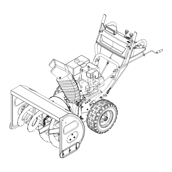
33" Snow Thrower
Model 1333 SWE
FORM NO.
770-10009C.fm
(11/2001)
Advertisement
Table of Contents

Related Manuals for Cub Cadet 1333 SWE


Summary of Contents for Cub Cadet 1333 SWE
- Page 1 Federal laws apply on federal lands. A spark arrester for the muffler is available through your nearest engine authorized service dealer or contact the service department, P.O. Box 368023 Cleveland, Ohio 44136-9722. CUB CADET CORP. P.O. BOX 368023 CLEVELAND, OHIO 44136-9722 770-10009C.fm PRINTED IN U.S.A.
-
Page 2: Table Of Contents
For future reference, please copy the model number and the serial number of the equipment in the space below. (Model Number) (Serial Number) Copy the model number here: CUB CADET CORP. Copy the serial number here: P.O. BOX 368023 CLEVELAND, OHIO 44136 CALLING CUSTOMER SUPPORT If you have difficulty assembling this product or have any questions regarding the controls, operation or maintenance of this unit, please call the Customer Dealer Referral Line. -
Page 3: Important Safe Operation Practices
SECTION 1: IMPORTANT SAFE OPERATION PRACTICES This symbol points out important safety instructions which, if not followed, could endanger the personal safety and/or property of yourself and others. Read and follow all instructions in this manual before attempting to operate this machine. Failure to comply with these instructions may result in personal injury. -
Page 4: Maintenance And Storage
Maintenance And Storage Never run an engine indoors or in a poorly ventilated area. Engine exhaust contains carbon monoxide, an Never tamper with safety devices. Check their proper odorless and deadly gas. operation regularly. Do not operate machine while under the influence of Disengage all clutch levers and stop engine. -
Page 5: Assembling Your Snow Thrower
SECTION 2: ASSEMBLING YOUR SNOW THROWER NOTE: Any reference in this manual to the left or right side of the snow thrower is observed from the operator’s position. Upper Handle Unpacking Steering Cable • Remove staples from the top, sides, and ends of the shipping crate. -
Page 6: Final Adjustments
shift rod. Tap the connector until it locks over the lower shift rod. See Figure 2. Alternator Lead NOTE: If the connector is not properly assembled, the shift rod will pivot and you will not be able to change Alternator speeds or change directions. -
Page 7: Knowing Your Snow Thrower
• Loosen the jam nut and thread the cable in (for less NOTE: Make certain the entire bottom surface of skid slack) or out (for more slack) as necessary. See shoe is against the ground to avoid uneven wear on the Figure 7. -
Page 8: Shift Lever
Shift Lever • Operate the snow thrower in open areas until becoming familiar with these controls. The shift lever is located in the center of the handle panel and is used to determine ground speed and Chute Tilt Control direction of travel. It can be moved into any of eight The distance snow is thrown can be changed by positions. -
Page 9: Operating Your Snow Thrower
SECTION 4: OPERATING YOUR SNOW THROWER Before Starting WARNING: The electric starter is equipped with a grounded three-wire WARNING: power cord and plug and is designed to Read, understand, and operate on 120 volt AC household follow all instructions and warnings on current. -
Page 10: Making Adjustments
To Stop Engine • Squeeze the traction control against the right handle and the snow thrower will move. Release it • Run engine for a few minutes before stopping to and the drive motion will stop. help dry off any moisture on the engine. NEVER move the shift lever without first IMPORTANT: •... -
Page 11: Maintaining Your Snow Thrower
Trigger Cables Shift Arm Drive Actuator Shift Lever Bracket Auger Actuator Bracket Hairpin Clip Hex Nut And Cupped Hex Gear Shaft Washer Flat Washer Ferrule Rubber Friction Shift Arm Upper Shift Rod Wheel Clutch Rod Drive Plate Connector Figure 10 Lower Shift Rod •... - Page 12 periodically to maintain your unit properly. hours of use. Apply the lubricant under the base of the • All adjustments in the service and adjustments chute and where the spirals contact the discharge sections of this manual should be checked at least chute.
-
Page 13: Servicing Your Snow Thrower
Check Friction Wheel Rubber Traction Control / Auger Control Lock Follow the instructions below to check the condition of The cams on the ends of the control rods which the friction wheel rubber every 25 hours of operation. interlock the traction drive and auger drive clutches must be lubricated at least once a season or every 25 •... - Page 14 against the slide shoes). Make certain the slide • Remove the large shoulder bolt and washer on the shoes are adjusted to be level. left hand side of the engine pulley. See Figure 16 • To remove the shave plate, remove slide shoe as Auger Belt well as the carriage bolts, belleville washers and •...
- Page 15 • Reassemble pulley to auger housing with hex should be checked after the first 25 hours of operation, screw and belleville washer (cupped side toward and periodically thereafter. Replace the friction wheel the pulley). Make sure key is in place on shaft and rubber if any signs of wear or cracking are found.
- Page 16 Engine • Reassemble the new friction wheel rubber to the friction wheel assembly, tightening the six screws in Refer to separate engine manual for all engine rotation and with equal force. It is important to maintenance procedures. assemble the rubber on the friction wheel symmetrically for proper functioning.
- Page 17 Auger control cable in need of adjustment. Refer to Final Adjustments in Assembly Auger belt loose or damaged. Section. Shear bolt(s) sheared. Refer to Adjustments. Replace shear bolt(s). NOTE: For repairs beyond the minor adjustments listed above, contact the local Cub Cadet dealer.
-
Page 18: Trouble Shooting Guide
Model 1333 SWE 34 26... -
Page 19: Parts List
Model 1333 SWE Ref. Ref. Part No. Part Description Part No. Part Description 05244A Bearing Housing 738-0281 Shoulder Screw 618-0281A Bracket Assembly: Auger Break 741-0185 Self-Aligning Bearing 684-0090A Impeller Assembly: 16” 741-0192 Flange Bearing w/ Flats 710-0371 Hex Lock Bolt 5/16-18 x .875”... - Page 20 Model 1333 SWE 53 69 5 54 27 75 61 48...
- Page 21 Model 1333 SWE Ref. Ref. Part No. Part Description Part No. Part Description 05523 Support Bracket: Pivot 732-0121 Extension Spring 618-0278 Bush Assembly 732-0209 Extension Spring 618-0279 Dogg Assembly LH 736-0119 Lock Washer 5/16 618-0280 Dogg Assembly RH 736-0158 Lock Washer 5/8...
- Page 22 Model 1333 SWE 22 11...
- Page 23 Model 1333 SWE Ref. Ref. Part No. Part Description Part No. Part Description 646-0012 Cable Assembly: Auger/Drive 749-0989A Upper Handle LH 684-0053B Chute Crank Assembly 749-0990A Upper Handle RH 705-5266 Chute Crank Bracket 749-0991 Lower Handle 710-3119 Hex Screw 3/8-16 x .75”...
- Page 24 Model 1333 SWE 6 15 Ref. Part No. Description 07386 Washer 684-0123A Belt Cover Bracket Assembly 710-0191 Hex Screw 3/8-24 x 1.25” 710-0237 Hex Screw 5/16-24 x .625” 710-0502A TT Sems Screw 710-0607 TT Screw 5/16-18 x 0.5” 710-1245 Hex Lock Screw 5/16-24 x .875”...
- Page 25 Model 1333 SWE Ref. Part No. Description 710-0276 Carriage Screw 710-0458 Carriage Bolt 5/16-18 x 1.75” 710-0805 Hex Bolt 5/16-18 x 1.5” 710-0896 Hex AB Screw 1/4-14 x .625” 710-3015 Hex Screw 1/4-20 x .75” 712-0429 Hex Lock Nut 712-3027...
- Page 26 Notes...
-
Page 28: Cleveland, Ohio
How to obtain service Contact your authorized Cub Cadet servicing dealer who sold you your Cub Cadet equipment. If this dealer is not available, see the Consumer Yellow Pages under “lawn mowers” for the name of a dealer near you.
Need help?
Do you have a question about the 1333 SWE and is the answer not in the manual?
Questions and answers