Table of Contents
Advertisement
Quick Links
O
M
PERATOR'S
ANUAL
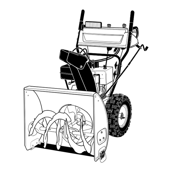
Model Series
1333SWE
Snow Thrower
IMPORTANT: READ SAFETY RULES AND INSTRUCTIONS CAREFULLY
Warning:
This unit is equipped with an internal combustion engine and should not be used on or near any unimproved forest-
covered, brush-covered or grass-covered land unless the engine's exhaust system is equipped with a spark arrester meeting
applicable local or state laws (if any). If a spark arrester is used, it should be maintained in effective working order by the operator.
In the State of California the above is required by law (Section 4442 of the California Public Resources Code). Other states may have
similar laws. Federal laws apply on federal lands. A spark arrester for the muffler is available through your nearest engine authorized
service dealer or contact the service department, P.O. Box 368023 Cleveland, Ohio 44136-9722.
CUB CADET CORP. P.O. BOX 368023 CLEVELAND, OHIO 44136-9722
FORM NO. 770-10009A
PRINTED IN U.S.A.
(06/99)
Advertisement
Table of Contents

Related Manuals for Cub Cadet 1333SWE Series


Summary of Contents for Cub Cadet 1333SWE Series
-
Page 1: Snow Thrower
Federal laws apply on federal lands. A spark arrester for the muffler is available through your nearest engine authorized service dealer or contact the service department, P.O. Box 368023 Cleveland, Ohio 44136-9722. CUB CADET CORP. P.O. BOX 368023 CLEVELAND, OHIO 44136-9722 FORM NO. 770-10009A PRINTED IN U.S.A. -
Page 2: Section 1: Finding Your Model Number
• Every snow thrower has a model plate. You can locate it by standing behind the unit in the operating position and looking down at the frame cover. • The model plate will look like Figure 1. XXX-X-XXX-X-XXX XXXXXXXXXXX CUB CADET CORP. P.O. BOX 368023 CLEVELAND, OHIO 44136 SECTION 2: CALLING WARRANTY SERVICE If you are having difficulty assembling this product or if you have any question regarding the controls, operation or maintenance of this unit, please call the Customer Dealer Referral Line. -
Page 3: Section 3: Important Safe Operation Practices
SECTION 3: IMPORTANT SAFE OPERATION PRACTICES WARNING: THIS SYMBOL POINTS OUT IMPORTANT SAFETY INSTRUCTIONS WHICH, IF NOT FOLLOWED, COULD ENDANGER THE PERSONAL SAFETY AND/OR PROPERTY OF YOURSELF AND OTHERS. READ AND FOLLOW ALL INSTRUCTIONS IN THIS MANUAL BEFORE ATTEMPTING TO OPERATE YOUR SNOW THROWER. FAILURE TO COMPLY WITH THESE INSTRUCTIONS MAY RESULT IN PERSONAL INJURY. -
Page 4: Maintenance And Storage
• If the snow thrower should start to vibrate abnormally, stop the engine and check immediately for the cause. Vibration is generally a warning of trouble. • Stop engine whenever you leave the operating position, before unclogging the collector/impeller housing or discharge guide, and making any repairs, adjustments, or inspections. -
Page 5: Section 4: Set-Up Instructions
SECTION 4: SET-UP INSTRUCTIONS Shear Bolts 5/16-18 x 1-1/2" Long (710-0890A) Hex Lock Nuts 5/16-18 Thread (712-0429) Wing Nuts, Washers and Bolts Figure 3 Wing Nut, Washer Bolt Figure 4 Upper Shift Connector Lower Shift Rod Figure 5 AUGER SHEAR BOLTS The augers are secured to the auger shaft with two shear bolts and hex lock nuts. -
Page 6: Final Adjustments
Cable Guide Figure 6 11. If not already attached, slip the cables that run from the handle panel to the chute into the cable guide located on top of the engine. See Figure 12. Unwrap the headlight wire which is attached to the headlight, beneath the handle panel. -
Page 7: Section 5: Controls
SECTION 5: CONTROLS Chute Auger Tilt Drive Control Clutch Left Headlight Trigger Lever Chute Directional Control Figure 10 SHIFT LEVER (See Figures 10 and 11) The shift lever is located in the center of the handle panel. The shift lever may be moved into one of eight positions. -
Page 8: Section 6: Operation
SECTION 6: OPERATION NOTE: This unit has been shipped with oil in the engine. Check oil before starting engine. GAS AND OIL FILL-UP Check oil level and add oil if necessary. Service the engine with gasoline as instructed in the separate engine manual packed with your snow thrower. -
Page 9: Section 7: Adjustments
TO STOP ENGINE 1. Run engine for a few minutes before stopping to help dry off any moisture on the engine. 2. To help prevent possible freeze-up of starter, proceed as follows: Optional Electric Starter Connect power cord to switch box on engine, then to 120 volt AC receptacle. -
Page 10: Section 8: Lubrication
SHIFT ROD ADJUSTMENT To adjust the shift rod, remove the cotter pin which secures the shift rod to the shift lever. For proper adjustment, refer to FINAL ADJUSTMENTS on page SKID SHOE ADJUSTMENT The space between the shave plate and the ground can be adjusted. -
Page 11: Section 9: Maintenance
SECTION 9: MAINTENANCE WARNING: Disconnect the spark plug wire and ground against the engine before performing maintenance. AUGERS The augers are secured to the spiral shaft with two shear bolts and hex lock nuts. See Figure 16. If you hit a foreign object or ice jam, the snow thrower is designed so that the shear bolts will shear. - Page 12 Engine Pulley Shoulder Figure 18 Auger Idler Ferrule Brake Bracket Assembly “Z” Fitting Figure 19 Frame Assembly Figure 20 8. Separate the auger housing from the frame assembly by tilting the housing forward and pulling up the handles. 9. Using a 1/2” wrench remove the hex screw and belleville washer from the centre of the pulley on the auger housing.
-
Page 13: Section 10: Off-Season Storage
Changing the Friction Wheel The rubber on the friction wheel is subject to wear and should be checked after 25 hours of operation, and periodically thereafter. Replace the friction wheel rubber if signs of excessive wear or cracking are found. 1. -
Page 14: Section 11: Trouble Shooting Guide
SECTION 11: TROUBLE SHOOTING GUIDE Trouble Possible Cause(s) Engine fails to start Fuel tank empty, or stale fuel. Blocked fuel line. Choke not in ON position Faulty spark plug. Key not in switch on engine. Spark plug wire disconnected. Primer button not depressed. Fuel shut-off valve closed Engine runs erratic Unit running on CHOKE. -
Page 15: Section 12: Illustrated Parts
SECTION 12: Illustrated Parts Model 1333SWE Ref. 731-1364 710-1240 712-0271 725-1669 629-0059 725-1658 710-0451 710-1003 736-0159 712-0429 731-0061 735-0225 705-5217 Part No. Description Halogen Lamp Housing Phillips Pan Head Screw M 4 x 16 Hex Sems Nut 1/4-20 Lamp/Lens Housing Ass’y Halogen Light Wire Harness #890 Halogen Bulb Carriage Bolt 5/16-18 x .75... - Page 16 Model 1333SWE...
- Page 17 Model 1333SWE Ref. Part No. Description 720-0232 Sml Shift Knob 705-5218 Engage Handle RH 705-5219 Engage Handl LH 710-0351 Pan Head B-tapp Scr #10 x .5 710-0599 Hwhd Sf-tap Scr 1/4-20 x 1/2 Lg. 711-0653 Clevis Pin .31 Dia x 1.0 712-3010 Nut Hex 5/16-18 Gd 5 714-0507...
- Page 18 Model 1333SWE...
- Page 19 Model 1333SWE Ref. Part No. Description 736-0159 Flat Washer .344 ID x .875 OD 710-3015 Truss. Hd. Mach. Scr. 1/4-20 x .75 736-0105 Belleville washer 731-0903D 6” Lower Chute Remote Tilt 784-5711 Chute Bracket 784-5123 Chute Bracket 731-1696 Chute Adapter 736-0242 Bell.
- Page 20 Model 1333SWE...
- Page 21 756-0240 756-0241B 784-5726 712-0324 732-0705 736-0173 Label No. Description 777D03024 Handle Panel Cub Cadet Power Steering 777D03039 Cub Cadet 1333SWE Top of Auger 777D03031 13 Hp OHV Side of Engine 777S30004 Top of Chute Danger/Warning 777S30005 Top of Auger Danger/Warning...
- Page 22 Model 1333SWE...
- Page 23 Model 1333SWE Ref. Part No. Description 05523 Pivot Axle Brkt. .63 Hole - Zinc 618-0278 Bush Asm slev 618-0279 Dogg Asm Dr Lh 618-0280 Dogg Asm Dr Rh 618-0282A Shf Asm Dr 618-0296 Whl Asm Brg 6.0 OD Friction 684-0115 Brkt Asm Supt Friction Dr 684-0116 Arm Asm Shift...
- Page 24 There is no other express warranty. Contact your authorized Cub Cadet servicing dealer who sold you your Cub Cadet equipment. If this dealer is not available, see the Consumer Yellow Pages under “lawn mowers” for the name of a dealer near you.
Need help?
Do you have a question about the 1333SWE Series and is the answer not in the manual?
Questions and answers