Furuno FM-8900S Installation Manual
Vhf radiotelephone
Hide thumbs
Also See for FM-8900S:
- Operator's manual (136 pages) ,
- Installation manual (61 pages) ,
- Gmdss manual (6 pages)
Table of Contents
Advertisement
Installation Manual
VHF RADIOTELEPHONE
FM-8900S
Model
SAFETY INSTRUCTIONS ................................................................................................ i
SYSTEM CONFIGURATION ........................................................................................... ii
EQUIPMENT LISTS........................................................................................................ iii
1. HOW TO INSTALL THE EQUIPMENT....................................................................... 1
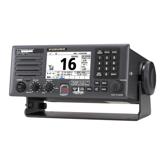
1.1 Transceiver Unit FM-8900S ..................................................................................................1
1.2 VHF Antenna ........................................................................................................................2
1.3 CH70 RX Antenna ................................................................................................................3
1.4 Handset Hanger....................................................................................................................3
1.5 AC-DC Power Supply Unit PR-240.......................................................................................3
1.6 Printer ...................................................................................................................................4
1.7 Printer Interface IF-8500 .......................................................................................................4
1.8 Loudspeaker SEM-21Q ........................................................................................................4
1.9 Junction Box IF-8900 ............................................................................................................5
1.10 Remote Station RB-8900, Watertight Remote Station RB-8900-W ......................................6
1.11 VHF Console RC-8900 .........................................................................................................7
2. CONNECTIONS.......................................................................................................... 8
2.1 Power Supply........................................................................................................................8
2.2 VHF Antenna ........................................................................................................................9
2.3 CH70 RX Antenna ................................................................................................................9
2.4 Handset HS-2003 .................................................................................................................9
2.5 How to Ground the Transceiver Unit.....................................................................................9
2.6 Junction Box .......................................................................................................................10
2.7 How to Connect the Remote Station without the Junction Box...........................................12
2.8 AC/DC Power Supply Unit PR-240 .....................................................................................13
2.9 When the Handset HS-2003 is not Connected to the Transceiver Unit..............................14
2.10 Rainproof Cover for Transceiver Unit .................................................................................14
2.11 Jumper Setting for Termination...........................................................................................15
2.12 VHF Console.......................................................................................................................16
2.13 I/O Data...............................................................................................................................17
3. HOW TO ASSEMBLE THE VHF CONSOLE KIT .................................................... 18
4. INITIAL SETTINGS................................................................................................... 21
4.1 How to Register the MMSI and ATIS ID .............................................................................21
4.2 Service Menu ......................................................................................................................22
4.3 Settings Inside the Transceiver Unit ...................................................................................25
APPENDIX 1 JIS CABLE GUIDE .............................................................................AP-1
PACKING LISTS ......................................................................................................... A-1
OUTLINE DRAWINGS ................................................................................................ D-1
INTERCONNECTION DIAGRAMS.............................................................................. S-1
www.furuno.com
All brand and product names are trademarks, registered trademarks or service marks of their respective holders.
Advertisement
Table of Contents

Related Manuals for Furuno FM-8900S


Summary of Contents for Furuno FM-8900S
-
Page 1: Table Of Contents
SAFETY INSTRUCTIONS ....................i SYSTEM CONFIGURATION ................... ii EQUIPMENT LISTS......................iii 1. HOW TO INSTALL THE EQUIPMENT............... 1 1.1 Transceiver Unit FM-8900S ....................1 1.2 VHF Antenna ........................2 1.3 CH70 RX Antenna ........................3 1.4 Handset Hanger........................3 1.5 AC-DC Power Supply Unit PR-240..................3 1.6 Printer ...........................4... - Page 2 ・FURUNO Authorized Distributor/Dealer 9-52 Ashihara-cho, Nishinomiya, 662-8580, JAPAN A : APR 2012 Printed in Japan All rights reserved. D : AUG . 26, 2013 Pub. No. IME-56800-D (GREG ) FM-8900S 0 0 0 1 7 6 2 0 3 1 3...
-
Page 3: Safety Instructions
IEC 60945 10 W/m 0.39 m IEC 60945 Standard Steering compass compass 2 W/m MPE by FCC 0.89 m FM-8900S 0.50m 0.30m (MPE: Minimum Permissible Exposure) IF-8900 2.05m 1.35m Turn off the power at the mains switch- HS-2003 1.50m 0.95m board before beginning the install- ation. -
Page 4: System Configuration
SEM-21Q ANALOG WING PLOTTER HANDSET PRINTER JUNCTION TRANSCEIVER HS-6000FZ5/ MIC RECEPTACLE PP-520/ UNIT* HS-6000FZ11 BOX RBD-VHF (B) PP-8800A IF-8900 FM-8900S MIC RECEPTACLE ANALOG WING PRINTER BOX RBD-VHF (B) HANDSET INTERFACE HS-6000FZ5/ IF-8500 REMOTE STATION HS-6000FZ11 RB-8900/RB-8900-W REMOTE STATION PRINTER RB-8900/RB-8900-W... -
Page 5: Equipment Lists
EQUIPMENT LISTS Standard supply Name Type Remarks Transceiver Unit FM-8900S Select one Installation Materials CP05-12600 1 set For transceiver unit w/inst. mat. CP05-12601, cable assy. LP-02-1(7A)-L3000 Accessories FP05-05730 1 set For HS-2003-15 FP05-05720 For HS-2003-15-L Spare Parts SP05-06201 1 set... - Page 6 EQUIPMENT LISTS Name Type Code no. Remarks External Loud- SEM-21Q 001-165-970-10 speaker Dynamic Mic. Set OP05-57 000-045-775 Receptacle Box: RBD-VHF(B)-75BG Hanger: AP-102 Handset: HS-6000FZ5 (dynamic mic., curled cable) Handset Set OP05-42 000-045-778 Receptacle Box: RBD-VHF(B)-75BG Hanger: AP-102 Handset: HS-6000FZ11 (dynamic mic., straight cable) MIC Receptacle RBD-VHF(B)-75BG...
-
Page 7: How To Install The Equipment
This chapter shows you how to install the units of the system. The transceiver unit and handset are standard supply. All other units are optional supply. (The junction box is standard supply in some installations.) Transceiver Unit FM-8900S 1.1.1 General installation remarks The transceiver unit can be installed on a desktop (with hanger), under a desktop, overhead, bulkhead, or in a console (requires a flush mount kit). -
Page 8: Vhf Antenna
1. HOW TO INSTALL THE EQUIPMENT 1.1.3 Console installation (flush mount, option) Requires the optional flush mount kit (OP05-129), the contents of which are shown in the table below. Follow the instructions in the outline drawing to install the unit in a con- sole. -
Page 9: Ch70 Rx Antenna
1. HOW TO INSTALL THE EQUIPMENT 1.2.3 Mounting procedure The basic mounting procedure for the antennas supplied by FURUNO is as follows; however, consult appropriate outline drawing for details. 1. Fasten the antenna bracket to the stanchion. 2. Set the antenna to the antenna bracket and tighten bolts. -
Page 10: Printer
2. Set the printer to the cutout and fasten the printer with four self-tapping screws (4×16). Printer Interface IF-8500 The Printer Interface IF-8500 allows the FM-8900S and other MF/HF radio communi- cation equipment to share the Printer PP-520. See the outline drawing at the back of this manual for installation instructions. -
Page 11: Junction Box If-8900
Fixing Fixing hole hole CABLE SLOT SIDE = Hole where to attach Card spacer waterproofing seal To FM-8900S To install the junction box, open the cover and fasten the box with four self-tapping screws (5×20). Close the cover. -
Page 12: Remote Station Rb-8900, Watertight Remote Station Rb-8900-W
1. HOW TO INSTALL THE EQUIPMENT 1.10 Remote Station RB-8900, Watertight Remote Station RB-8900-W A maximum of four remote stations can be installed. 1. Remove six screws on the handset hanger. 2. Remove upper chassis of the hanger. 3. Fasten the base of the hanger to a bulkhead with two self-tapping screws (4×20). 4. -
Page 13: Vhf Console Rc-8900
1. HOW TO INSTALL THE EQUIPMENT 1.11 VHF Console RC-8900 Install the VHF console where you can easily operate the equipment in the console and do maintenance and service. Meet with shipyard personnel and ship's officer-in- charge to select the best location. The location must meet the following points: •... -
Page 14: Connections
CONNECTIONS Connect external equipment at the rear of the transceiver unit. 4.7A CH70 RX ANT 24VDC 24VDC CH70 RX ANT Connect power Connect DSC cable. antenna. GND terminal SPKR Connect ground wire. JUNCTION PRINTER JUNCTION SPKR Connect Junction Box Connect external IF-8900. -
Page 15: Vhf Antenna
2. CONNECTIONS VHF Antenna The VHF antenna is connected to the transceiver unit with a 50 ohm coaxial cable, type RG-10/U-Y. Make sure you leave some additional length in the cable for future service and maintenance. Lay the coaxial cable and fasten an M-type plug to the cable (if necessary) as follows. 1. -
Page 16: Junction Box
2. CONNECTIONS Junction Box The junction box connects external equipment to the transceiver unit. The cable that connects between the junction box and the transceiver unit is pre-connected to the junction box. WAGO connectors connect the external equipment. A terminal opener is provided inside the junction box to open terminals on the connectors. - Page 17 2. CONNECTIONS Cable TTYCSLA-1 (NAV equipment) 5 - 6 Crimp-on more Vinyl tape than Cover shield with shrink tubing. L*=Depends on location of connector. See illustration of junction box on page 9 for length. Cable TTYCSLA-4 (Alarm Unit IC-350, INS, AIS, Plotter, MIC Receptacle Box, Remote Handset 5 - 6 Crimp-on...
-
Page 18: How To Connect The Remote Station Without The Junction Box
2. CONNECTIONS 2.6.3 How to fasten the cables to the Junction Box Connect cables to related connectors. Fasten the cables to the cable posts with two cable ties. Fasten cable to post with two cable ties. How to Connect the Remote Station without the Junction Box The remote station (MIC receptacle box, etc.) can be connected directly to the trans- ceiver unit, using the D-sub connector supplied as installation materials. -
Page 19: Ac/Dc Power Supply Unit Pr-240
2. CONNECTIONS AC/DC Power Supply Unit PR-240 The AC/DC Power Supply Unit PR-240 is shipped ready for connection to 200-230 VAC. For connection to 100 VAC-115 VAC, change the tap connection and terminal board connection as below. Attach applicable label (supplied in accessories) to the front panel according to the ship's mains. -
Page 20: When The Handset Hs-2003 Is Not Connected To The Transceiver Unit
2. CONNECTIONS Protective earth Connect a IV-2sq wire between the ship’s ground and the ground terminal on the PR- 240 to prevent electrical shock. CAUTION Attach protective earth securely to the ship's ground. The protective earth (grounding) is required to prevent electrical shock. GND terminal When the Handset HS-2003 is not Connected to the Transceiver Unit... -
Page 21: Jumper Setting For Termination
2. CONNECTIONS 2.11 Jumper Setting for Termination For termination on the remote stations, open the remote handset hanger as shown be- low. The default setting for J2 is “ON” (jumper block connected to pins 2 and 3). Con- firm this setting. Re-connect the connector to the circuit board. Confirm that the plastic washers are in the screw holes in the handset hanger then close the hanger. -
Page 22: Vhf Console
2. CONNECTIONS 2.12 VHF Console Install the VHF console following Chapter 3, then following the procedure in this sec- tion. VHF console 1. Remove the cover assembly and printer assembly (or concealing lid) from the console. For the printer assembly, remove the cables connected to the transceiver unit and the terminal board. -
Page 23: I/O Data
2. CONNECTIONS 3. Connect the antenna coaxial cable as shown below. GNSS cable How to connect the coaxial cable: 1. Make a loop in the coaxial cable. 2. Fasten the coaxial cable to the GNSS cable with a cable tie. 3. -
Page 24: How To Assemble The Vhf Console Kit
HOW TO ASSEMBLE THE VHF CONSOLE KIT A VHF console kit is required to install the transceiver unit in the VHF console. There are two types of consoles, with a printer and without a printer. 1. Remove the cover assembly, the panel assembly and the printer assembly (or concealing lid) from the console. - Page 25 3. HOW TO ASSEMBLE THE VHF CONSOLE KIT 3. Set the transceiver unit to the console upside down. Fasten the transceiver unit to the rack case as shown below. Hex bolt Insert console upside down. Rack case Spacer Transceiver unit bolt Spacer Plain...
- Page 26 3. HOW TO ASSEMBLE THE VHF CONSOLE KIT 6. Connect the following to the transceiver unit: • fuse to the power connector on the transceiver unit • For the console with printer, connect the printer cable to the PRINTER port. (For no printer, fasten the concealing lid.) •...
-
Page 27: Initial Settings
This chapter shows you how to enter the initial settings, which requires a password. Refer to FURUNO Information for the password. Entry of the MMSI and ATIS ID* num- bers also requires a short inside the junction box or at the rear panel of the transceiver unit. -
Page 28: Service Menu
4. INITIAL SETTINGS 4. Use the numeric keys to enter the MMSI. Confirm the number then push the CH knob to submit the number. 5. If applicable, enter the ATIS ID like how you entered the MMSI. Note: You can re-enter the MMSI/ATIS ID if it is wrong. Select the applicable [CLEAR] then push the CH knob. -
Page 29: Rt Setup Menu
4. INITIAL SETTINGS 4.2.2 RT SETUP menu The [RT SETUP] menu has the initial settings for the radiotelephone section. Normal- ly, adjustment of the items in this menu is not required. For information, see the Ser- vice Manual. 4.2.3 CH CONFIG menu The [CH CONFIG] menu sets the TRX state, communication type and output power for every channel. -
Page 30: Other Menu
4. INITIAL SETTINGS 4.2.4 OTHER menu for SERVICE P-BROWSER: Activate or deactivate the parameter browser, which is controlled from a PC. For use by the service technician. AMS MODE: AMS MODE selects whether an AMS (Alert Management System) is connected to this radio or not. There are two choices, [LEGACY] and [DNV]. Select [DNV] when this radio is connected to an AMS. -
Page 31: Settings Inside The Transceiver Unit
4. INITIAL SETTINGS Settings Inside the Transceiver Unit Various jumper blocks are provided inside the transceiver unit to customize the sys- tem according to local regulations, user requirements, specifications, etc. 4.3.1 MIC type, MULTI SIO port receive format type, alarm output Turn the transceiver unit upside down. - Page 32 4. INITIAL SETTINGS 4.3.2 VHF antenna only If a CH70 antenna is not installed, CH70 can be received with a VHF TX-RX antenna. Do the modification below to enable CH70 reception with a VHF TX-RX antenna. Note however that CH70 cannot be received during VHF transmission. Remove the outer cover and the shield cover to show the TRX_WR Board (05P0841).Connect the supplied mini-pin assy.
-
Page 33: Appendix 1 Jis Cable Guide
EX: DPYCYSLA - 1.5 MPYC - 4 TTYCSLA-4 Core Area (mm Designation type Designation type # of cores The following reference table lists gives the measurements of JIS cables commonly used with Furuno products: Core Cable Core Cable Diameter Diameter... - Page 46 Y. Hatai...
- Page 50 T.Matsuguchi Sep.21'06...
- Page 51 D-10 Feb.02'05...
- Page 52 D-11...
- Page 53 D-12 Y.NISHIYAMA 8/Mar/2010 Y.NISHIYAMA 29/Aug/2012...
- Page 54 D-13...
- Page 55 D-14 Dec.26'03...
- Page 56 D-15 Dec.26'03...
-
Page 57: Interconnection Diagrams
IV-1.25sq. DRAWN TITLE FM-8900S T.YAMASAKI 12/Mar/2013 CHECKED 名称 国際VHF無線電話装置 H.MAKI 12/Mar/2013 注記 NOTE APPROVED 相互結線図 Y.NISHIYAMA 14/Mar/2013 *1)造船所手配。 *1: SHIPYARD SUPPLY. SCALE MASS NAME VHF RADIOTELEPHONE *2)オプション。 *2: OPTION. DWG.No. REF.No. INTERCONNECTION DIAGRAM C5680-C01- F 05-104-2001-0 FURUNO ELECTRIC CO., LTD. - Page 58 H.MAKI 12/Mar/2013 注記 NOTE APPROVED 相互結線図 FM-8900S Y.NISHIYAMA 14/Mar/2013 *1)造船所手配。 *1: SHIPYARD SUPPLY. SCALE MASS NAME VHF RADIOTELEPHONE (RACK CONSOLE) *2)オプション。 *2: OPTION. *3)Nタイプでは支給なし。 DWG.No. REF.No. *3: NOT SUPPLIED FOR RC-8900-N. INTERCONNECTION DIAGRAM C5680-C02- G 05-104-8001-0 FURUNO ELECTRIC CO., LTD.