Table of Contents
Advertisement
Available languages
Available languages
Advertisement
Chapters
Table of Contents

Subscribe to Our Youtube Channel
Related Manuals for Montarbo E616A


Summary of Contents for Montarbo E616A
- Page 1 SERIES 2-way, active loudspeaker systems Instruction manual Manuale istruzioni...
- Page 2 Per evitare il rischio di incendio e/o folgorazione, non smontarlo e non rimuovete i pannelli. Per qualsiasi intervento di manutenzione o riparazione, rivolgetevi alla Elettronica Montarbo srl e/o a personale altamente qualificato specificamente segnalato da questa. - Al momento dell'installazione del sistema, verificare che la forma e le caratteristiche delle strutture di appoggio siano adatte allo scopo, considerando sia il peso che l'ingombro del prodotto.
-
Page 3: Table Of Contents
6 - CURA E MANUTENZIONE DEL PRODOTTO ..........34 7 - DATI TECNICI DEL SISTEMA ..............35 SCHEMA A BLOCCHI ..................70 C ON TE N U TO - sistema attivo biamplificato E616A ® - cavo di alimentazione con connettore PowerCon DELL 'IM B A LL O... -
Page 4: Introduzione E Applicazioni
1 - INTRODUZIONE E APPLICAZIONI 1.1 - INTRODUZIONE E616A è un sistema biamplificato full-range a 2 vie di ridotte dimensioni che nasce dall’esperienza maturata sui sistemi delle serie FULL e WIDE e rappresenta un concentrato di trasportabilità ed efficienza. Concepito per la massima versatilità d’uso, grazie anche al controllo del... -
Page 5: Descrizione Del Sistema
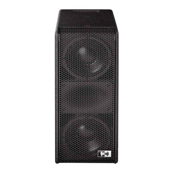
2 - DESCRIZIONE DEL SISTEMA a Driver a compressione da 1” (bobina da 1.7“) caricata a tromba 80° x 60° tractrix. b 2 woofer da 6” (bobina da 2.5“), in configurazione D’Appolito, con magnete al neodimio schermato e superventilato. Cabinet in multistrato di betulla da 15 mm, vernice poliuretanica anti-abrasioni. - Page 6 PANNELLO CONNESSIONI E CONTROLLI PUSH VOL. NEUTRIK NEUTRIK NEUTRIK LINK SUB OUT prot clip Preset User Both = Enter DOWN ITALIANO...
- Page 7 7 - Connettori RJ45 delle porte DATA, per il collegamento all'interfaccia USBNet Montarbo LD2.4 e/o ad un altro diffusore delle serie E616. Usare normali cavi ETHERNET a 8 poli (CAT5 o superiore). Per informazioni più dettagliate, vedere par. 4.3.
- Page 8 WIDE153 / WIDE123 - COMANDI DSP B C D prot clip Preset User down Both = Enter DOWN A - LED verde 'sig' (signal): indica la presenza di segnale in ingresso. B - LED rosso 'clip': indica la saturazione (clipping) dello stadio di ingresso del DSP interno.
-
Page 9: Installazione E Cablaggio
Il diffusore E616A può essere montato su aste di supporto standard, utilizzando l'adattatore incorporato (i: pag. 5). - Page 10 • Se il mixer ha uscite bilanciate XLR: utilizzare dei normali connettori XLR bilanciati. • Se il mixer ha uscite sbilanciate XLR e non è un Montarbo: è bene accertarsi che le uscite XLR del mixer siano sbilanciate a norme IEC 268 e cioé...
-
Page 11: Cavo Di Alimentazione
- 7,5A = assorbimento massimo del sistema E616A). L'assorbimento totale delle apparecchiature alimentate dal cavo collegato alla presa 1 (l'assorbimento del sistema E616A sommato a quello di tutte le apparecchiature collegate alla presa AC LOOP OUT) deve quindi essere inferiore a 20A. -
Page 12: Cablaggio Del Connettore Powercon
® 3.2.1 - Cablaggio del connettore PowerCon 20 mm Spelare il cavo per una lunghezza di 8 mm 20 mm ed ogni singolo filo per una lunghezza di 8 mm. Consigliamo l'utilizzo di un cavo di alimentazione con conduttori aventi sezione di almeno 3 x 1,00 mm fili cavo... -
Page 13: Cablaggio Del Sistema
3.3 - CABLAGGIO DEL SISTEMA Collegamento alla rete - Accertarsi che la tensione di alimentazione corrisponda a quella indicata sul pannello. - Collegare il cavo di alimentazione ad una presa di corrente dotata di contatto di terra di sicura efficienza 3.3.1 - Cablaggio dei cavi di segnale Le prese di ingresso IN (4) e di LINK (5) sono su connettori XLR 3 poli femmina (IN) e maschio (LINK). - Page 14 • Se il mixer ha uscite bilanciate XLR: utilizzare dei normali connettori XLR bilanciati. • Se il mixer ha uscite sbilanciate XLR e non è un Montarbo: è bene accertarsi che le uscite XLR del mixer siano sbilanciate a norme IEC 268 e cioé...
-
Page 15: Collegamento In Parallelo Di Più Sistemi
3.4 - COLLEGAMENTO IN PARALLEO DI PIU' SISTEMI Collegare l'uscita LINK alla presa di ingresso IN dell'altro sistema, come illustrato nella figura seguente. VOL. VOL. LINK SUB OUT LINK SUB OUT prot prot clip clip Preset User Both = Enter Both = Enter MAINS Nel caso si volesse alimentare il secondo sistema mediante la presa AC... -
Page 16: Uso Dell'apparecchio
Il LED Sub2 indica che l'uscita è filtrata (banda 35÷100Hz, 18 dB/ottava), per l'uso con subwoofer attivi privi di filtraggio incorporato (o con subwoofer passivi pilotati da un amplificatore di potenza esterno). Il DSP del sistema E616A controlla la risposta in frequenza del subwoofer. ITALIANO... - Page 17 La tabella seguente riporta la descrizione dei preset di fabbrica. Tutti i preset hanno l'uscita subwoofer abilitata. DESCRIZIONE NUMERO CONFIG. (led) NATURAL FLAT LOUDNESS LONG THROW FRONTFILL FLAT NATURAL FLAT + uscita subwoofer a banda larga (per sub serie TANK) P1 + Sub1 NATURAL FLAT + uscita subwoofer filtrata (per sub serie BX) P1 + Sub2...
-
Page 18: Collegamento Ad Un Personal Computer
4.3 - COLLEGAMENTO AD UN PERSONAL COMPUTER È necessario l'uso dell'interfaccia USB opzionale LD2.4 Mediante essa è possibile controllare fino a 10 diffusori attivi E616A. Collegare una delle prese DATA (7) all'interfaccia LD2.4 con un cavo ETHERNET CAT5 (con connettori RJ45) e l'interfaccia LD2.4 al personal computer con un cavo USB (tipo A-B). -
Page 19: Software Raconls
'FULL', 'SPOT', 'WIDE' e serie 'E'. SCOLLEGATO dal PC. Non utilizzare versioni previste per altri apparecchi Montarbo. Inserendo nel lettore del personal computer il CD fornito con l'interfaccia LD 2.4, viene mandato in esecuzione automatica un programma di installazione che permetterà... - Page 20 Seguire le indicazioni del setup wizard per personalizzare l'installazione. Cliccate su Next. Comparirà la schermata seguente, in cui si chiede di accettare il contratto di licenza. Se si vuole continuare l'installazione, selezionare "I accept the agreement", quindi cliccare Next. ITALIANO...
- Page 21 Apparirà questa schermata, in cui si chiede dove si vuole installare il programma. Scrivere il percorso su cui copiare i file oppure lasciare la destinazione predefinita. Nella schermata successiva, è possibile selezionare il nome del gruppo di programmi che verrà creato nel menu START.
- Page 22 Nella schermata successiva, scegliere se creare o no le icone aggiuntive sul desktop e/o nella barra di avvio ® veloce di Windows Una volta selezionate le varie opzioni, il programma è pronto a copiare i file sul PC. Cliccate Install e il programma RAConLS verrà...
- Page 23 Dopo il programma RAConLS, il processo di installazione continua con l'installazione del driver USB dell'interfaccia USBnet LD2.4, necessaria per comunicare con i sistemi attraverso la linea seriale RS485FD. Durante l'installazione il cavo USB DEVE RIMANERE SCOLLEGATO dal PC. Durante l'installazione del driver USB, il sistema operativo mostrerà...
- Page 24 Con la schermata successiva l'installazione del programma viene ultimata. Ora è possibile collegare il cavo USB e l'interfaccia LD2.4. Il PC riconosce il nuovo hardware e ne effettua la registrazione nel sistema. Il software è gia presente sul PC, quindi non è necessario eseguire la ricerca: selezionare "No, non ora"...
- Page 25 è il software da installare: Lasciare la selezione consigliata (automatico) e cliccare Avanti. Come in precedenza, saltare il messaggio Windows Logo cliccando su Continua. Se richiesto, selezionare Montarbo USBNet e cliccare Avanti. ITALIANO...
- Page 26 L'installazione continua con la registrazione dell'hardware per l'utilizzo del driver installato. Al termine della procedura l'interfaccia LD2.4 e Montarbo USBNet sono pronti per essere utilizzati. ITALIANO...
-
Page 27: Utilizzo Del Programma
All'avvio il programma inizia la ricerca dell'interfaccia USB LD2.4 Se questa è scollegata nella casella dei messaggi viene indicato NoDevice. In questo caso inserire il cavo USB e l'interfaccia LD 2.4 ed attendere la comparsa della scritta Montarbo USBNet e successivamente Status OK. ITALIANO... - Page 28 Se il programma è già stato utilizzato precedentemente, con una certa configurazione di diffusori, nella finestra in alto a sinistra comparirà la lista dei diffusori registrati e nella parte inferiore dello schermo le finestre corrispondenti ai vari diffusori. Nel caso di primo utilizzo del programma, o nel caso in cui sia stata cambiata la configurazione dei diffusori, occorre procedere alla loro registrazione, in modo che il programma RAConLS li possa riconoscere e quindi li possa controllare.
-
Page 29: Preparazione Della Lista Dei Diffusori
5.3.1 - Preparazione della lista dei diffusori Il diffusore Montarbo E616A ha, incorporato nel software del DSP interno, un identificativo (nome) univoco, nel formato esadecimale 'Hxxxxxxxxxxxxxxx' che lo distingue da tutti gli altri (un 'numero di matricola' digitale). Per procedere alla registrazione dei diffusori, cliccare sul pulsante StartAW in alto a sinistra. -
Page 30: Finestra Comando Controller
5.3.2 - Finestra comando controller IMPORTANTE: I diffusori collegati sono visualizzati a coppie sinistro / destro (L/R). In seguito è descritto come sia possibile il comando contemporaneo dei due diffusori di una coppia. L'ordine in cui sono visualizzati e quindi suddivisi in coppie corrisponde all'ordine in cui sono stati registrati premendo i tasti UP e DOWN. - Page 31 Questa è la finestra di comando, dove è possibile intervenire su tutti i parametri modificabili. A sinistra compare un indicatore di livello del segnale di ingresso. L'accensione dell'indicatore rosso in alto indica la saturazione del convertitore A/D. Nel caso di due diffusori che formano una coppia (come descritto nella pagina precedente) l'indicatore di livello sarà...
- Page 32 A destra in alto compare l'indicazione della temperatura ambiente (Ta1) e degli amplificatori di potenza (Tf1). Nel caso di due diffusori che formano una coppia le temperature indicate saranno 4: Ta1 e Tf1 per il primo diffusore e Ta2 e Tf2 per il secondo. A destra compare la finestra di controllo del volume (attenuazione di uscita).
-
Page 33: Gestione Dei Preset
Se quindi sul diffusore viene impostato il preset 0 (User Preset), all'accensione sarà attivo il preset modificato. Eventuali nuovi preset che saranno resi disponibili da Montarbo potranno essere caricati salvandoli sul PC e richiamandoli come descritto precedentemente. -
Page 34: Cura E Manutenzione Del Prodotto
6 - CURA E MANUTENZIONE DEL PRODOTTO • Questo prodotto è stato progettato per essere utilizzato in climi tropicali e particolarmente caldi. • Non porre sulla cassa sorgenti di fiamme nude, quali candele accese. • Posizionare la cassa lontano da fonti di calore (caloriferi o qualsiasi altro oggetto che produca calore). -
Page 35: Dati Tecnici Del Sistema
· XLR bilanciati per ingresso e link · uscita DSP per pilotaggio di subwoofer esterni · RJ45 DATA delle due porte seriali RS485FD per il collegamento remoto a PC (Montarbo net) · PowerCon® per l’alimentazione (ingresso + link) · controllo di volume ·... - Page 36 This products does not contain user serviceable parts. To prevent fire and/or electrical shock, never disassemble it or remove the rear panel. For maintenance and servicing always refer to the official Montarbo Distributor in your Country or to qualified personnel specifically authorized by the Distributor.
- Page 37 ® Thank you for the preference you have shown by purchasing the Montarbo E616A system. This manual contains important information about installing and operating the product correctly and safely. Read this manual carefully in order to thoroughly familiarize yourself with these procedures.
-
Page 38: Introduction And Applications
The on-board electronics is based on the Montarbo DSP controller (56 bit, 180 MHz, 24 bit conversion) which handles all the filtering, equalizing, delaying, limiting and diagnostics functions. -
Page 39: E616A - System's Description
2 - SYSTEM'S DESCRIPTION a 1" high-quality compression driver (1.7" voice coil) loaded by a wide dispersion (80° H x 60° V) horn, tractrix. b 2 x 6” woofer (2.5“ voice coil), with shielded supervented neodymium magnet, arranged in a ‘D’Appolito’ configuration. Cabinet made from 15 mm birch plywood, with high-impact, chip-resistant paint. - Page 40 CONTROLS AND CONNECTIONS PANEL PUSH VOL. NEUTRIK NEUTRIK NEUTRIK LINK SUB OUT prot clip Preset User Both = Enter DOWN ENGLISH...
- Page 41 7 - RJ45 sockets of the two DATA ports: they are intended for connection to the Montarbo USBNet control network: a Montarbo LD 2.4 USBNet interface and/or another E616A active speaker system. Use standard 8 poles ETHERNET cables (CAT5 or higher).
- Page 42 DSP CONTROLS B C D prot clip Preset User down Both = Enter DOWN A - Green LED 'sig' (signal): it lights up when an input signal is detected. B - Red LED 'clip': it lights up when a clipping (excess of signal level) is detected in the input stage of the internal DSP.
-
Page 43: Installation And Wiring
The E616A speaker system may be placed over standard speaker supports stand by means of built-in adapter (i: page 39). Wire the system's components as described in the following figure. - Page 44 • If the mixer has XLR unbalanced outputs: in this case, unless using a Montarbo mixer, make sure that the XLR outputs on the mixer are unbalanced to IEC 268 standard 1 = GND, 2 = HOT, 3 = GND.
-
Page 45: Mains Cable
AC LOOP OUT socket (2) is 12.5A (20A: max current rating of POWERCON ® input socket - 1 - minus 7.5A = maximum current drained by E616A system). The maximum current drain of the sum of the devices powered by the... -
Page 46: Wiring Of Powercon ® Connector
® 3.2.1 - Wiring of PowerCon connector 20 mm Strip the cable for 20 mm of length 8 mm and strip each wire for 8 mm of length. We suggest to use a power cable with at least 3 x 1,00 mm section wires (the insert terminals can however support a cable with wires wires... -
Page 47: System Wiring
3.3 - SYSTEM WIRING AC mains connection - Make sure that the ac line voltage value corresponds to the one indicated on rear panel. - Connect the mains supply cable to a socket fitted with a proven ground contact. 3.3.1 - Wiring of signal cables The input socket IN (4) and the LINK socket (5) are XLR 3 pole connectors, female (IN) and male (LINK). - Page 48 • If the mixer has XLR unbalanced outputs: in this case, unless using a Montarbo mixer, make sure that the XLR outputs on the mixer are unbalanced to IEC 268 standard 1 = GND, 2 = HOT, 3 = GND.
-
Page 49: Parallel Connection Of Multiple Systems
3.4 - PARALLEL CONNECTION OF MULTIPLE SYSTEMS Connect the LINK output to the IN input of the other system, as shown in the following image. MAINS If you need to supply ac power to the second system, using the first system's AC LOOP OUT socket, use a suitable cable, at least 3 x 1,0 mm terminated with a POWERCON ®... -
Page 50: Operation
The Sub1 LED indicates that the output's signal is wide-band (10 to 200 Hz) and suitable to drive a subwoofer that is equipped with an internal cross- over filter (like all Montarbo active sub-woofers) The Sub2 LED indicates that the output signal is band-limited (25 to 100 Hz,... - Page 51 The following table has a description of the four factory presets. In the first 4 presets (number 1 to 4) the SUB OUT output is disabled. DESCRIPTION NUMBER CONFIG. (LED) NATURAL FLAT LOUDNESS LONG THROW FRONTFILL FLAT NATURAL FLAT + wide range subwoofer output (TANK series subwoofer) P1 + Sub1 NATURAL FLAT + band-limited subwoofer output (BX series subwoofer) P1 + Sub2...
-
Page 52: Connection To A Personal Computer
4.3 - CONNECTION TO A PERSONAL COMPUTER For this application the optional USB interface model LD2.4 is required. With it the user may control any combination of up to 10 E616A active speaker system. Connect one of the DATA connectors (7) to the LD2.4 interface with an ETHERNET CAT5 cable (with RJ45 plugs) and the USB port of the LD2.4... -
Page 53: Raconls Software
USB cable MUST BE UNPLUGGED active loudspeakers. FROM THE PC. Do not use other versions specified for other Montarbo products. Insert the CD that comes with the LD2.4 interface unit into the computer drive. A self-executing installation program will be launched that will allow you to select the version of the program to be installed. - Page 54 Follow the instructions provided by the setup wizard to customize the installation. Click on the Next button. The following window will open, asking you to accept the license agreement. If you want to continue the installation process, click on 'I accept the agreement', and then click on 'Next'.
- Page 55 This window will open, asking which folder you want the program installed into. Write the folder name, or browse to search for it, or simply accept the default folder. The following window allows you to select the program's group name in the Start Menu.
- Page 56 The following window allows you to create icons for the program on the Desktop and/or in the Quick launch bar. Once the various options have been selected, the installation program is ready to copy the program's files to the PC. Click on Install and the RAConLs program will be installed in your PC.
- Page 57 After completing installation of the RaConLS program, the process will continue with the USB driver for the USBnet – LD2.4 interface, required for the PC to communicate with the speaker's DSP controllers via the RS485FD serial interface. During the installation the USB cable MUST BE UNPLUGGED FROM THE PC.
- Page 58 The following window will display when the RAConLS program setup process has been completed. Now it is possible to plug in the USB cable and the LD24 interface. The PC will detect the new hardware and will add it to the system's registry.
- Page 59 Use the suggested method (recommended) and click Next. As you did previously, ignore the Windows Logo compatibility message by clicking on Continue Anyway. If requested, select Montarbo USBNet and click on Next. ENGLISH...
- Page 60 The installation process continues with the egistration of the new hardware and its driver. At the end of the process, the LD2.4 interface and the Montarbo USBNet are ready for use. ENGLISH...
-
Page 61: Using The Program
PC, the message window will show NoDevice. In this case, plug in the USB interface with an USB cable to the PC and wait for the Search… message to disappear. The message window will show Montarbo USBNet for a short time, then Status OK. ENGLISH... - Page 62 If the program has been previously used with a certain configuration of speakers, the upper-left window will display the list of the registered speakers, and the lower part of the screen will display a group of windows corresponding to the above speakers. The first time the program is used and each time the configuration of the speakers is altered it will be necessary to register them in the program's database, so that the RAConLS program may acknowledge them and duly...
-
Page 63: Build The Speaker's List
5.3.1 - Building the speaker's list Each speaker system in the Montarbo's FULL, SPOT, WIDE and 'E' series has, permanently written in the internal DSP's software, a unique ID (name) in the hexadecimal format 'Hxxxxxxxxxxxxxxx', that will distinguish it from all the others (a digital 'serial number'). -
Page 64: Main Controller's Windows
5.3.2 - Main controller window IMPORTANT: The networked speakers are displayed as Left / Right pair. The two speakers in a L/R pair may be linked together and both controlled at the same time, as will be described in the following paragraphs. The order in which the speakers are displayed is the same as the order in which they were registered by pushing the UP and DOWN buttons. - Page 65 This is the command window from which it is possible to work on all modifiable parameters. At the left a bar-graph indicates the input levels. The red indicator light will go on when an A/D converter overload is detected. When two speakers are linked to form an L/R pair (as described in the previous page), the input level will be indicated by a stereo bar-graph (one bar for each speaker).
- Page 66 On the upper-right side of the windows are displayed both the ambient (external) temperature (Ta1) and the power amplifier’s temperature (Tf1). When two speakers are linked to form an L/R pair the window will display four temperatures values: Ta1 and Tf1 for the first speaker, Ta2 and Tf2 for the second.
-
Page 67: Management Of Presets
So, if the speaker's selected preset is the number 0 (User Preset), it will be the default preset at switch-on. Any future updated preset which may be made available from Montarbo will be loaded the same way: first saved on the PC as preset files, then recalled and stored as described above. -
Page 68: Products Care And Maintenance
6 - PRODUCT'S CARE AND MAINTENANCE • This product has been designed for use in tropical climates and particularly warm weather conditions. • Never place burning candles or other sources of open flame on top of the device. • Never expose the enclosure to heat sources (heaters or other products that produce heat). -
Page 69: Technical Data
Connections and controls · Balanced XLR connectors for input, link · processed output for driving external subwoofer · RJ45 DATA connectors for the connection to a PC (Montarbo net) · PowerCon® for mains power supply (input + link) · Volume control ·... -
Page 70: Schema A Blocchi
In the European Union If the product is used for business purposes and you want to discard it: please contact your Montarbo dealer who will inform you about the take-back of the product. You might be charged for the costs arising from take-back and recycling. Small products (and small amounts) might be taken back by your local collection facilities. - Page 71 ENGLISH...
- Page 72 Siamo a vostra disposizione per fornirvi eventuali ulteriori informazioni e consigli. La Elettronica Montarbo srl non può essere ritenuta responsabile per danni o incidenti a cose o persone, causati o connessi all’utilizzazione o malfunzionamento dell’apparecchio.
Need help?
Do you have a question about the E616A and is the answer not in the manual?
Questions and answers