Table of Contents
Advertisement
Quick Links
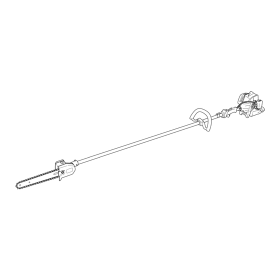
PRODUCT NAME
Hitachi Engine Pole Saw
CS 27EPAP(S)
Models
CS 27EPA(S)
CONTENTS
TROUBLESHOOTING GUIDE ---------------------------------------------------------------------------------------------- 1
1. Troubleshooting and correction ------------------------------------------------------------------------------- 1
REPAIR GUIDE ----------------------------------------------------------------------------------------------------------------- 3
1. Precaution on maintenance, inspection and repair ------------------------------------------------------ 3
2. Inspection criteria for each section and consumable parts -------------------------------------------- 3
LIST Nos.
CS 27EPAP: F021
CS 27EPA: F020
Sep. 2012
Page
International Sales Division
Advertisement
Table of Contents

Related Manuals for Hitachi CS 27EPAP(S)


Summary of Contents for Hitachi CS 27EPAP(S)
- Page 1 LIST Nos. CS 27EPAP: F021 CS 27EPA: F020 Sep. 2012 PRODUCT NAME Hitachi Engine Pole Saw CS 27EPAP(S) Models CS 27EPA(S) CONTENTS Page TROUBLESHOOTING GUIDE ---------------------------------------------------------------------------------------------- 1 1. Troubleshooting and correction ------------------------------------------------------------------------------- 1 REPAIR GUIDE ----------------------------------------------------------------------------------------------------------------- 3 1. Precaution on maintenance, inspection and repair ------------------------------------------------------ 3 2.
-
Page 2: Troubleshooting Guide
TROUBLESHOOTING GUIDE 1. Troubleshooting and correction Problem Cause Corrective action Seized piston ring Seized connecting rod bearing Starter grip Crank shaft does not turn. Disassemble and cannot be Seized piston and cylinder replace. pulled. Worn piston or cylinder Crank shaft turns. Defective starter body ass'y Empty fuel tank Replenish with fuel. - Page 3 Problem Cause Corrective action Clogged carburetor ass’y Clean. Engine speed fluctuates. Defective carburetor ass’y Check or replace. Defective carburetor ass’y Check or replace. Engine Consumes excessive fuel. Clogged cleaner element of cleaner Clean. starts but ... ass’y Improper idling adjustment Adjust.
-
Page 4: Repair Guide
REPAIR GUIDE This section describes troubleshooting and repair procedures for common phenomena that may occur during pole saw operation. The procedures described here and in the “TROUBLESHOOTING GUIDE” should be studied and referenced as needed to ensure efficient diagnosis and prompt repair of problems. 1. -
Page 5: Repair Flow Chart
Repair flowchart Refer to page Pull the starter handle. Disassemble and Seized piston ring 12, 13 replace. Is pulling possible? Seized connecting rod Disassemble and 12, 13 bearing replace. Disassemble and Seized piston and cylinder 12, 13 replace. Disassemble and Defective starter body ass'y 11, 12 replace. - Page 6 Refer to page Stained or defective Clean or Engine starts. spark plug replace. Does combustion continue? Weak spark Improper air gap Adjust. Defective ignition coil Replace. ass'y Defective piston ring Replace. 12, 13 Weak Defective oil seals of compression Replace. 12, 13 crank case ass'y Clogged carburetor...
- Page 7 Refer to page Insufficient amount of chain oil in the Supply oil. Is chain oil discharged? oil tank Clogged chain oil discharge port Clean. 15, 16, 17 Clogged chain bar oil feed port Clean. 15, 16, 17 Clogged oil filter Clean.
-
Page 8: Starting The Engine
Inspection and repair procedures [Bold] numbers in the descriptions below correspond to item numbers in the Parts List and exploded assembly diagram for the Model CS 27EPAP; <Bold> numbers correspond to those in the Parts List and exploded assembly diagram for the Model CS 27EPA. 1. -
Page 9: Wiring Diagram
3. Adjusting air gap (clearance) between the magneto rotor comp. periphery and ignition coil ass'y (1) Remove the Muffler Cover [4]<4>, Cylinder Cover [1]<1>, and Fan Case [118]<118>. (2) Loosen the two Hex. Hole Bolts 4 x 18WS [127]<127> so as to tighten the Ignition Coil Ass'y [128]<128>... - Page 10 Be careful of the installation angle and the press-connecting direction of the Earth Cord [130]<130>. Press-connecting portion Earth Cord [130]<130> Washer T1.6 [16]<16> 45º±10º Screw [129] or Screw M4<129> Ignition Coil Ass'y [128]<128> Flange Nut M4 [132] or Flange Nut M14 <132> 5.
- Page 11 Carburetor Ass'y [48]<48> Fuel Pipe 3 x 5 x 85 [138]<138> Shield Tube 3 x 5 x180 [137]<137> Tank [143]<143> Tank Cap Ass'y [139]<139> Tank Cap Chain [140]<140> Pump Filter Body Comp. [146]<146> 9. Checking and adjusting the carburetor ass'y (1) Checking the Carburetor Ass'y [48]<48>...
-
Page 12: Disassembly And Reassembly
Disassembly and reassembly Do not reuse the following parts. • Cover Packing [13]<13> • Intake Packing [42]<42> • Seal Lock Hex. Socket Hd. Bolt M5 x 30 [9]<9> • Hex. Hole Bolt 5 x 20S [11]<11> • Hex. Hole Bolt 4 x 12WS [15]<15> •... - Page 13 center. Next, loosen the two Step Bolts [120]<120> and then remove the Clutch Set [123]<123>. To remove the Starter Pulley Ass'y [67]<66>, lock the Crank Shaft Ass’y [60]<59> and lightly strike the Starter Pulley Ass'y [67]<66> with a plastic hammer to turn it counterclockwise. NOTE: Use a clean wire rope to lock the crank shaft.
- Page 14 (3) Reassembling the crank case ass’y, piston set, and cylinder set When press-fitting the Oil Seal TB12227 [63]<62> into the Exhaust mark (arrow) Piston Set PN [55]<54> Crank Case Ass'y [61]<60>, position the pressurizing spring inside, and then fill the gap between the lips with Pyronoc Universal No.
- Page 15 4. Disassembling the gear case section (1) Slightly loosen the Chain Bar Clamp Nut [227]<227> while being careful not to remove it. Turn the Oil Pump Adjuster [217]<217> counterclockwise to decrease the tension of the Saw Chain [225]<225>. NOTE: Turning the Oil Pump Adjuster [217]<217> counterclockwise decreases the tension of the Saw Chain [225]<225>;...
- Page 16 5. Reassembling the gear case section (1) Reassembling the gear case section First, press-fit the Ball Bearing 627 C3 [199]<199> into the Case [220]<220>. NOTE: Be careful not to tilt the Ball Bearing 627 C3 [199]<199>. Confirm that the Screw 6 x 8 [189]<189> is tightened. Apply seven to nine grams of specified Cosmo Molybdenum No.
- Page 17 Attach the Oil Tank Gasket [177]<177> to the Case [220]<220>, and then apply Turbine Oil 56 (Nippon Oil & Energy) to the O-ring P-5 [178]<178>. Attach the Oil Tank Cover [176]<176> to the Case [220]<220> with the four Small Screws 4 x 12WS [209]<209>, while carefully avoiding contact with the Filter Ass’y [211]<211>...
- Page 18 To check proper tension, lightly lift up the center of the Saw Chain [225]<225> and there should be about 0.5 to 1.0 mm clearance between the Chain Bar 10 [226]<226> and the edge of the drive link of the Saw Chain [225]<225> (when drawing it out at load of 1 kg.) CAUTION: PROPER TENSION IS EXTREMELY IMPORTANT! Raise the end of the Chain Bar 10 [226]<226>...
-
Page 19: Tightening Torque
Tightening torque Thread Tightening torque Location Part name dia. (N•m {kgf•cm}) Crank case ass’y Hex. Hole Bolt 5 x 20S [11]<11> 5 mm 4.0 to 8.0 {41 to 81} Cylinder Hex. Hole Bolt 5 x 20S [11]<11> 5 mm 6.0 to 9.0 {62 to 91} Scavenging cover Hex. - Page 20 LIST NO. F021 ENGINE ENGINE POLE SAW 2012 · 9 · 13 Model CS 27EPAP (E1)
- Page 21 CS 27EPAP - 2 - 9 - 12...
- Page 22 CS 27EPAP 9 - 12 - 3 -...
- Page 23 CS 27EPAP ITEM CODE NO. DESCRIPTION REMARKS USED 669-8481 CYLINDER COVER HITACHI LABEL 669-5376 SCREW 4 X 22/PS 669-8494 MUFFLER COVER 669-5386 SCREW 5 X 16/PS 669-5067 HEX. HOLE BOLT 6 X 65 668-4639 BOLT WASHER 6 669-8476 MUFFLER (B) 669-8950 SEAL LOCK HEX.
- Page 24 PARTS CS 27EPAP ITEM CODE NO. DESCRIPTION REMARKS USED MARK PLATE (T) MARK PLATE (EU) 669-0347 CLEANER ELEMENT 669-0139 AIR CLEANER CAP 669-8961 AIR FILTER ASS'Y INCLUD. 52, 53 669-7683 PISTON SET PN INCLUD. 56, 57 668-6121 PISTON RING 668-4590 CIR CLIP 668-4591 PISTON PIN 669-5590 NEEDLE BEARING HK0810B 669-8969 CRANK SHAFT ASS'Y...
- Page 25 668-4835 HEX. NUT 6 668-9681 BRAKE SHAFT WASHER 669-5255 TAPPING SCREW 5 X 20 669-8515 CAP (A) 668-4851 LEVEL MARK CAUTION PLATE HITACHI 668-4852 LEVEL MARK 669-8823 MAIN PIPE COMP. 668-9443 DRIVE SHAFT 1829L 668-9277 HANGER D24 669-1134 HANDLE BRACKET A...
- Page 26 668-4741 STOP RING C-28, INNER 668-5962 COLLAR 668-9117 SPROCKET COMP., 3/8 669-5170 FLANGE NUT 6 668-6038 SIDE COVER COMP. 669-4763 SYMBOL MARK HITACHI 669-5403 SMALL SCREW 4 X 12WS COLLAR 3 669-0913 FILTER ASS'Y INCLUD. 212, 213 669-0917 OIL FILTER...
- Page 27 STANDARD ACCESSORIES CS 27EPAP ITEM ITEM CODE NO. CODE NO. DESCRIPTION REMARKS USED USED 669-3809 COMBI. BOX SPANNER 13 X 19 MINUS 668-4766 WRENCH 8 X 10 668-4813 HEX. BAR WRENCH 4 MM 669-4796 GUIDE BAR COVER, 10 669-2867 SHOULDER BELT OPTIONAL ACCESSORIES ITEM CODE NO.
- Page 28 LIST NO. F020 ENGINE ENGINE POLE SAW 2012 · 9 · 13 Model CS 27EPA (E1)
- Page 29 CS 27EPA - 2 - 9 - 12...
- Page 30 CS 27EPA 9 - 12 - 3 -...
- Page 31 CS 27EPA ITEM CODE NO. DESCRIPTION REMARKS USED 669-8481 CYLINDER COVER HITACHI LABEL 669-5376 SCREW 4 X 22/PS 669-8493 MUFFLER COVER 669-5386 SCREW 5 X 16/PS 668-4638 HEX. HOLE BOLT M6 X 55 668-4639 BOLT WASHER 6 669-8477 MUFFLER 669-8950 SEAL LOCK HEX. SOCKET HD. BOLT M5 X 30 669-8491 HEAT PROTECTION PANEL 669-5491 HEX.
- Page 32 PARTS CS 27EPA ITEM CODE NO. DESCRIPTION REMARKS USED 669-5431 PLUS SCREW 5 X 60WS 669-0347 CLEANER ELEMENT 669-0139 AIR CLEANER CAP 669-8961 AIR FILTER ASS'Y INCLUD. 51, 52 669-7683 PISTON SET PN INDLUD. 55, 56 668-6121 PISTON RING 668-4590 CIR CLIP 668-4591 PISTON PIN 669-5590 NEEDLE BEARING HK0810B 669-8969 CRANK SHAFT ASS'Y...
- Page 33 668-4835 HEX. NUT 6 668-9681 BRAKE SHAFT WASHER 669-5255 TAPPING SCREW 5 X 20 669-8515 CAP (A) 668-4851 LEVEL MARK CAUTION PLATE HITACHI 668-4852 LEVEL MARK 669-8823 MAIN PIPE COMP. 668-9443 DRIVE SHAFT 1829L 668-9277 HANGER D24 669-1134 HANDLE BRACKET A...
- Page 34 668-4741 STOP RING C-28, INNER 668-5962 COLLAR 668-9117 SPROCKET COMP., 3/8 669-5170 FLANGE NUT 6 668-6038 SIDE COVER COMP. 669-4763 SYMBOL MARK HITACHI 669-5403 SMALL SCREW 4 X 12WS COLLAR 3 669-0913 FILTER ASS'Y INCLUD. 212, 213 669-0917 OIL FILTER...
- Page 35 STANDARD ACCESSORIES CS 27EPA ITEM ITEM CODE NO. CODE NO. DESCRIPTION REMARKS USED USED 669-3809 COMBI. BOX SPANNER 13 X 19 MINUS 668-4766 WRENCH 8 X 10 668-4813 HEX. BAR WRENCH 4 MM 669-4796 GUIDE BAR COVER, 10 669-2867 SHOULDER BELT OPTIONAL ACCESSORIES ITEM CODE NO.
Need help?
Do you have a question about the CS 27EPAP(S) and is the answer not in the manual?
Questions and answers