
Related Manuals for Microplex SOLID F40


Summary of Contents for Microplex SOLID F40
- Page 1 ________________________________________________________________________________ SOLID F40 Operator’s Manual Edition 1.1 ________________________________________________________________________________...
- Page 2 _______________________________________________________________________________________________ _______________________________________________________________________________________________...
-
Page 3: Table Of Contents
Attaching the Printer to a Network/Computer 4.2. Printer Power on 4.3. Control Panel View 4.4. Function of the Control Panel Elements 4.5. Configuration via the Control Panel 4.6. Menu Structure 4.7. Syntax of Diagrams _______________________________________________________________________________________________ MICROPLEX Operator’s Manual SOLID F40 Edition 1.1... -
Page 4: Chapter Page
Image Shifting to the Y-Direction 5.25. Lines per Inch Setting (Line Spacing) 5.26. Number of Characters per Inch Setting (Character Spacing) 5.27. Print Density Setting 5.28. Configuration of Network Parameters (IP Address, e.g.) _______________________________________________________________________________________________ MICROPLEX Operator’s Manual SOLID F40 Edition 1.1... - Page 5 8.2.1. Error Codes 8.3. Paper Jam 8.3.1. Paper Jam inside the Tractor 8.3.2. Paper Jam inside the Print System 8.3.3. Paper Jam within the Power Stacker 8.4. Print Repetition after an Error _______________________________________________________________________________________________ MICROPLEX Operator’s Manual SOLID F40 Edition 1.1...
-
Page 6: _______________________________________________________________________________________________
Table of Contents _______________________________________________________________________________________________ Chapter Page 9. Measures for Transport and Shipping (Repacking) 10. Specifications 11. Index _______________________________________________________________________________________________ MICROPLEX Operator’s Manual SOLID F40 Edition 1.1... -
Page 7: Introduction
_______________________________________________________________________________________________ 1. Introduction 1.1. General Description The print system SOLID F40 works on an electrophotographical base employing an LED array as exposure unit. The maximum resolution of 600 dots per inch is corresponding to about 24 pixels per mm. The print speed is up to 40 A4 pages (landscape) per minute. -
Page 8: _______________________________________________________________________________________________
Introduction _______________________________________________________________________________________________ The MICROPLEX printer controller has its integrated website, this allows a printer configuration via Ethernet. See Networking Features of MICROPLEX Printers for more information. Consequently there is a multitude of scopes for this print system. It is suitable for high-speed printing with excellent print quality using different types of materials. -
Page 9: Conventions
[ Menu Level 1 ] This symbol is used to show a shining LED (light emitting diode). The SOLID F40 printer panel is provided with several LEDs. The real shape of the LEDs differs from the shape of this symbol (compare figure in section 4.3). -
Page 10: Ce - Conformity
Introduction _______________________________________________________________________________________________ 1.3. CE — Conformity _______________________________________________________________________________________________ MICROPLEX Operator’s Manual SOLID F40 Edition 1.1... -
Page 11: General Safety Instructions
This device produces, employs and possibly radiates high frequency energy. Because of this, incorrect installation can disturb radio communications. This MICROPLEX product and its consumables are designed and tested according to strict safety standards. Heeding the following instructions ensures secure operation: - Make sure that your electricity source is grounded adequately. -
Page 12: _______________________________________________________________________________________________
- After switching off the device, wait at least 15 seconds before restarting the printer. - Please follow all the information and hints directly attached to the device and/or described in this manual. _______________________________________________________________________________________________ MICROPLEX Operator’s Manual SOLID F40 Edition 1.1... -
Page 13: Installation
Please make sure that all items are included and that there are no defects. Immediately inform your supplier of any damage. Open the cardboard box carefully and check the contents: 1. MICROPLEX Printer SOLID F40 2. CD containing: • Operator’s Manual SOLID F40 •... -
Page 14: Printer Installation
- Do not expose the printer to shocks or vibrations. - The printer should not be located near volatile or combustible materials (e.g. a curtain). The printer’s first installation has to be done by a trained service engineer. _______________________________________________________________________________________________ MICROPLEX Operator’s Manual SOLID F40 Edition 1.1... -
Page 15: _______________________________________________________________________________________________
- Use the printer only within the allowable fluctuation range +10% of the power voltage. Conditional connection for the SOLID F40: The maximum permissible system impedance Z is appr. 0.02 Ohm. The user of this device has to determine in consultation with the supply... -
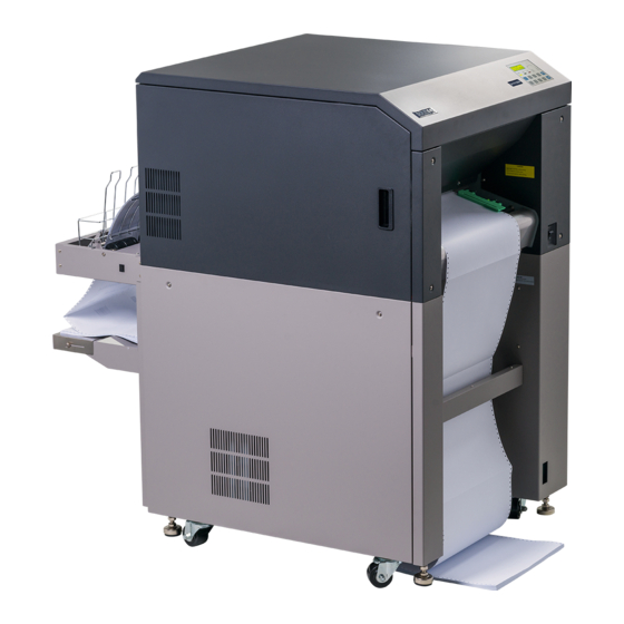
Page 16: Printer Components
Installation _______________________________________________________________________________________________ 2.3. Printer Components External Views: Control panel Tractor Front cover Power switch Lower front cover Paper near end sensor Control panel Interfaces _______________________________________________________________________________________________ MICROPLEX Operator’s Manual SOLID F40 Edition 1.1... -
Page 17: _______________________________________________________________________________________________
Installation _______________________________________________________________________________________________ Interfaces (Detail View): Centronics Ethernet Printer interior view: Cleaning unit Front cover Toner cartridge Fuser unit Developer unit Transport unit Main charger Waste toner recovery unit Drum plate _______________________________________________________________________________________________ MICROPLEX Operator’s Manual SOLID F40 Edition 1.1... -
Page 18: Handling Of Consumables
Cleaning the Transport Unit) and chapter 7 Operator Maintenance (especially section 7.1 Charger Cleaning). 1. Turn the printer OFF LINE. 2. Make sure the left tractor is in the left position. Left tractor Control panel Guide with paper sensor _______________________________________________________________________________________________ MICROPLEX Operator’s Manual SOLID F40 Edition 1.1... -
Page 19: _______________________________________________________________________________________________
Mark for the left paper margin 4. Pass the fanfold paper through the sensor guide (Paper Near End Sensor PNES). Guide with paper sensor Folded edge of the paper _______________________________________________________________________________________________ MICROPLEX Operator’s Manual SOLID F40 Edition 1.1... -
Page 20: _______________________________________________________________________________________________
(tractor lock lever) of the right tractor into the vertical position. Lock lever of the right tractor " " 6. Open the two tractor cover plates by turning them into the upright position. _______________________________________________________________________________________________ MICROPLEX Operator’s Manual SOLID F40 Edition 1.1... -
Page 21: _______________________________________________________________________________________________
Please note: exactly the same number of tractor pins has to be chosen on this tractor side (compare step 7). _______________________________________________________________________________________________ MICROPLEX Operator’s Manual SOLID F40 Edition 1.1... -
Page 22: _______________________________________________________________________________________________
9. Close the right tractor cover plate and tighten the paper gently with the right tractor. & To avoid paper jams the paper must not be inserted too lose or too tight. 10. Lock the right tractor by using the lock lever. _______________________________________________________________________________________________ MICROPLEX Operator’s Manual SOLID F40 Edition 1.1... -
Page 23: _______________________________________________________________________________________________
11. Turn the printer ON LINE. The newly aligned paper will be driven to the start position automatically. 12. If necessary adjust the printer to the new page length (see section 5.9). _______________________________________________________________________________________________ MICROPLEX Operator’s Manual SOLID F40 Edition 1.1... -
Page 24: Replacing The Toner Cartridge
5 % can be printed (compare chapter 10 Specifications). Please wear vinyl gloves to avoid dirty hands when replacing the cartridge. 1. Open the front cover of the printer. Front cover Handhold _______________________________________________________________________________________________ MICROPLEX Operator’s Manual SOLID F40 Edition 1.1... -
Page 25: _______________________________________________________________________________________________
On the occasion of every toner cartridge replacing the necessity of cleaning the developer unit has to be checked. Cleaning the developer unit has to be done in due time to avoid reduced print quality (see section 7.2). _______________________________________________________________________________________________ MICROPLEX Operator’s Manual SOLID F40 Edition 1.1... -
Page 26: _______________________________________________________________________________________________
4. Shake the new cartridge gently by performing horizontal movements to distribute the toner. 5. Put the end of the new cartridge into the SOLID F40 toner hopper with the adhesive tape facing up, and slowly strip off the tape from the front to the back. Slide the cartridge gently into the device in one operation. -
Page 27: _______________________________________________________________________________________________
The toner is easily combustible and should never come in contact with fire. Disposal will be carried out by your service engineer. Until disposal please store the cartridge in a vinyl bag in a closed cardboard box. _______________________________________________________________________________________________ MICROPLEX Operator’s Manual SOLID F40 Edition 1.1... -
Page 28: Replacing The Waste Toner Bottle
1. Open the front cover of the printer. Front cover Handhold 2. Press down the open lever of the waste toner recovery unit and open the unit. Waste toner recovery unit Open lever (black) _______________________________________________________________________________________________ MICROPLEX Operator’s Manual SOLID F40 Edition 1.1... -
Page 29: _______________________________________________________________________________________________
3. Take off the cap outside the waste toner recovery unit and close the bottle. Waste toner bottle 4. Take out the waste toner bottle completely. 5. Insert the new bottle into the waste toner recovery unit. _______________________________________________________________________________________________ MICROPLEX Operator’s Manual SOLID F40 Edition 1.1... -
Page 30: _______________________________________________________________________________________________
The waste toner is easily combustible and should never come in contact with fire. Disposal will be carried out by your service engineer. Until disposal please store the waste toner bottle in a vinyl bag in a closed cardboard box. _______________________________________________________________________________________________ MICROPLEX Operator’s Manual SOLID F40 Edition 1.1... -
Page 31: Operation And Menu Structure
2. Use a proper interface line to connect the printer to your computer or to the network. The printer SOLID F40 is provided with several interfaces; see chapter 10 Specifications for more information. 4.2. Printer Power on The power switch is located at the right side of the printer (see section 2.3... -
Page 32: Control Panel View
• information about the actual state of the device (panel and LEDs). • direct command input using the keyboard. Display (two-lined) ON LINE SOLID F40 2 lines of keys LEDs On / Off Line key _______________________________________________________________________________________________ MICROPLEX Operator’s Manual SOLID F40 Edition 1.1... -
Page 33: Function Of The Control Panel Elements
The phase of initializing is not yet completed. DATA The printer receives printable data. There are no printable data in the input buffer. ERROR An error occurred in the printer. The printer is OFF LINE. No error occurring. _______________________________________________________________________________________________ MICROPLEX Operator’s Manual SOLID F40 Edition 1.1... -
Page 34: _______________________________________________________________________________________________
Apart from that activating the FORM FEED key in the OFF LINE mode will move the paper one form length ahead. The last print job will be cut at its end and the paper will be moved SPLIT to the park position. _______________________________________________________________________________________________ MICROPLEX Operator’s Manual SOLID F40 Edition 1.1... -
Page 35: _______________________________________________________________________________________________
Status Sheet and section 5.8 Generating Test Prints, too). MENU These keys are used for working within the different levels of the menu structure. This structure and the panel functions are described in the following chapters. SAVE _______________________________________________________________________________________________ MICROPLEX Operator’s Manual SOLID F40 Edition 1.1... -
Page 36: Configuration Via The Control Panel
You can use the control panel to change the printer configuration and customize your printer to meet your specific needs. In addition printer configuration via Ethernet is possible. The MICROPLEX printer controller offers an integrated website, for more information see Networking Features of MICROPLEX Printers. -
Page 37: _______________________________________________________________________________________________
Now this message is shown by the display of the control panel. [Menu Level 1 ] In the interest of simplicity, in the following chapters only the most important display messages are shown in the Panel display column. _______________________________________________________________________________________________ MICROPLEX Operator’s Manual SOLID F40 Edition 1.1... -
Page 38: Menu Structure
Operation and Menu Structure _______________________________________________________________________________________________ 4.6. Menu Structure Access to the menu structure is possible as soon as the printer is turned OFF LINE. The SOLID F40 menu structure is arranged in different levels: ON LINE - Mode OFF LINE Menu Level 1... -
Page 39: _______________________________________________________________________________________________
The SAVE key has two main functions. It gives the user access to SAVE a particular menu and, once in the menu, it allows the user to select a particular function. [“Function“] _______________________________________________________________________________________________ MICROPLEX Operator’s Manual SOLID F40 Edition 1.1... -
Page 40: _______________________________________________________________________________________________
If the MENU key is pressed instead, the changes are only stored temporary (not saved as setup). (This key takes the user to the MENU respective previous menu level). _______________________________________________________________________________________________ MICROPLEX Operator’s Manual SOLID F40 Edition 1.1... -
Page 41: _______________________________________________________________________________________________
Pressing the MENU key takes the user back to the respective MENU menu level above. Return to the ON LINE mode: Pressing the ON LINE key switches the user directly to ON LINE ″ ON LINE ″ from any menu position. _______________________________________________________________________________________________ MICROPLEX Operator’s Manual SOLID F40 Edition 1.1... -
Page 42: Syntax Of Diagrams
The ″ Panel display ″ column shows the display messages ["Message"] corresponding to the sequences listed on the left. In the column ″ Notes ″ explanations to particular operational steps are given. _______________________________________________________________________________________________ MICROPLEX Operator’s Manual SOLID F40 Edition 1.1... -
Page 43: Panel Functions
Press the SAVE key. Menu level 1 is SAVE selected. [Status Sheet ] Press the SAVE key again. SAVE [Status Sheet ] A status sheet is printed. The printer is turned ON LINE ON LINE again. _______________________________________________________________________________________________ MICROPLEX Operator’s Manual SOLID F40 Edition 1.1... -
Page 44: _______________________________________________________________________________________________
/ left bottom / right Default character code Options Fonts installed (Font banks) Note: Use the panel function Printing the Font List to show the fonts installed (see the following section). _______________________________________________________________________________________________ MICROPLEX Operator’s Manual SOLID F40 Edition 1.1... -
Page 45: Printing The Font List
Press one of the ARROW keys until [Font List ] is displayed. ) ) ) [Font List ] SAVE The font list is printed. [Font List ] ON LINE The printer is turned ON LINE again. _______________________________________________________________________________________________ MICROPLEX Operator’s Manual SOLID F40 Edition 1.1... -
Page 46: Choosing Print Resolution
600 dpi resolution is selected. [Save as Setup? ] In addition this new value can be SAVE MENU saved as setup value (using the SAVE key), before the printer is ON LINE turned ON LINE again. _______________________________________________________________________________________________ MICROPLEX Operator’s Manual SOLID F40 Edition 1.1... -
Page 47: _______________________________________________________________________________________________
(300 dpi data stream), also the 300 dpi font banks (bitmap writing) are available. If 600 dpi resolution is chosen, the corresponding fonts must be loaded into the printer server (e.g. True Type fonts, scalable download fonts). _______________________________________________________________________________________________ MICROPLEX Operator’s Manual SOLID F40 Edition 1.1... -
Page 48: Hexdump Mode Activation
Note: By activating the normal print mode (see next section) or by turning the printer off and on again the printer can be taken out of Hexdump Mode. Time between turning the printer off and on again should be at least 15 seconds. _______________________________________________________________________________________________ MICROPLEX Operator’s Manual SOLID F40 Edition 1.1... -
Page 49: Normal Print Mode Activation (Incl. Form Feed)
This is necessary because after a test in the Hexdump Mode it is possible that data can remain in the input buffer unintentionally. (Cause: in the Hexdump Mode no control characters are evaluated and no FORM FEED i s effected). _______________________________________________________________________________________________ MICROPLEX Operator’s Manual SOLID F40 Edition 1.1... -
Page 50: Clearing The Input Buffer (Cancel Job)
[Cancel Job ] is displayed. ) ) ) [Cancel Job ] All data contained in the input buffer SAVE will be cleared. [Cancel Job ] The printer is turned ON LINE ON LINE again. _______________________________________________________________________________________________ MICROPLEX Operator’s Manual SOLID F40 Edition 1.1... -
Page 51: Printing The Menu Page
Press one of the ARROW keys until [Menu Page ] is displayed. ) ) ) [Menu Page ] A menu structure presentation of the SAVE SOLID F40 (see section 4.6) is printed. [Menu Page ] The printer is turned ON LINE ON LINE again. -
Page 52: Generating Test Prints (Sliding Pattern)
A status sheet is generated TEST (possibly printed on several pages) [Menu Level 1 ] The printer is turned ON LINE ON LINE again. Another way to activate the function: see the following page ! _______________________________________________________________________________________________ MICROPLEX Operator’s Manual SOLID F40 Edition 1.1... -
Page 53: _______________________________________________________________________________________________
A series of test prints is generated. [Sliding Pattern ] The printer is turned ON LINE ON LINE again. The printing out of test prints can be stopped by pushing the ON LINE key. _______________________________________________________________________________________________ MICROPLEX Operator’s Manual SOLID F40 Edition 1.1... -
Page 54: Page Length Adjustment
The page length is changed to 12.33 inches. [Save as Setup? ] In addition this new value can be saved as SAVE MENU setup value (using the SAVE key), before the printer is turned ON LINE again. ON LINE _______________________________________________________________________________________________ MICROPLEX Operator’s Manual SOLID F40 Edition 1.1... -
Page 55: _______________________________________________________________________________________________
The panel display shows the message [Load Paper ] ..After loading the corresponding paper the printer is turned ON LINE by using the ON LINE key. _______________________________________________________________________________________________ MICROPLEX Operator’s Manual SOLID F40 Edition 1.1... -
Page 56: Selecting The Number Of Printpages Per Page Format (Two-Up Mode)
2. [Save as Setup? ] In addition this new value can be saved MENU SAVE as setup value (using the SAVE key), before the printer is turned ON LINE ON LINE again. _______________________________________________________________________________________________ MICROPLEX Operator’s Manual SOLID F40 Edition 1.1... -
Page 57: _______________________________________________________________________________________________
All other page parameters have to be set optionally in accordance to the requirements. A simultaneous combination of several print images per formlength and several print images per form width isn’t possible until now. _______________________________________________________________________________________________ MICROPLEX Operator’s Manual SOLID F40 Edition 1.1... -
Page 58: Paper Width Adjusting (Format Width)
In addition this new value can be saved as setup value (using the SAVE key), before the ON LINE printer is turned ON LINE again. Note: Information for „Paper Request“ can be found in section 5.9 Page Length Adjustment. _______________________________________________________________________________________________ MICROPLEX Operator’s Manual SOLID F40 Edition 1.1... -
Page 59: Print Direction Selection
Print direction assignment: Print direction 0 = Portrait (upright format) Print direction 1 = Landscape (horizontal format) Print direction 2 = Portrait upside down Print direction 3 = Landscape upside down _______________________________________________________________________________________________ MICROPLEX Operator’s Manual SOLID F40 Edition 1.1... -
Page 60: Data Interface Configuration
ON ON LINE LINE again. Note: The printer uses SIA (Simultaneous Interface Administration) to check, which interface is currently used for the transfer of print data. _______________________________________________________________________________________________ MICROPLEX Operator’s Manual SOLID F40 Edition 1.1... -
Page 61: Emulation Selection
The emulation HP PCL 5 is selected. [Save as Setup? ] In addition this new value can be MENU SAVE saved as setup value (using the SAVE key), before the printer is ON LINE turned ON LINE again. _______________________________________________________________________________________________ MICROPLEX Operator’s Manual SOLID F40 Edition 1.1... -
Page 62: _______________________________________________________________________________________________
QMS (Magnum) Code V, ANSI Genicom, XEROX XES, HP DesignJet (HPGL-2), LDC (Label Description Language), Express (More emulations on request) Notice: The brand names mentioned are registered trademarks of the enterprises named above. _______________________________________________________________________________________________ MICROPLEX Operator’s Manual SOLID F40 Edition 1.1... -
Page 63: Display Language Selection
[Save as Setup? ] In addition this new value can be MENU SAVE saved as setup value (using the SAVE key), before the printer is ON LINE turned ON LINE again. _______________________________________________________________________________________________ MICROPLEX Operator’s Manual SOLID F40 Edition 1.1... -
Page 64: Transparent Code Adjustment
IDOL commands. MENU SAVE In addition this new value can be saved as setup value (using the SAVE key), before ON LINE the printer is turned ON LINE again. _______________________________________________________________________________________________ MICROPLEX Operator’s Manual SOLID F40 Edition 1.1... -
Page 65: Selection Of Memory Distribution (Input Buffer)
100 kB is selected as input buffer. [Save as Setup? ] In addition this new value can be MENU SAVE saved as setup value (using the SAVE key), before the printer is turned ON ON LINE LINE again. _______________________________________________________________________________________________ MICROPLEX Operator’s Manual SOLID F40 Edition 1.1... -
Page 66: Setting To Factory Default
[Save as Setup? ] Only if you press the SAVE key a second time the configuration will be MENU SAVE back-outed to factory defaults. ON LINE The printer is turned ON LINE again. _______________________________________________________________________________________________ MICROPLEX Operator’s Manual SOLID F40 Edition 1.1... -
Page 67: Font Selection
The font number 5507 is selected. [Save as Setup? ] In addition this new value can be SAVE saved as setup value (using the MENU SAVE key), before the printer is turned ON LINE again. ON LINE _______________________________________________________________________________________________ MICROPLEX Operator’s Manual SOLID F40 Edition 1.1... -
Page 68: _______________________________________________________________________________________________
Panel Functions _______________________________________________________________________________________________ The SOLID F40 standard equipment contains the following fonts : Font no. Font width Font height Font name 0600 Kurilen 0602 Kurilen Italic 0610 10.1 Kurilen 1710 10.1 Kurilen Italic 4508 Helgoland 4510 Helgoland 4714 14.4 Helgoland Bold... -
Page 69: _______________________________________________________________________________________________
Additional fonts can be selected from the font catalogue depending upon the memory capacity. You can use the panel function Printing the Font List (see section 5.2) to generate a list of all fonts installed to the printer. _______________________________________________________________________________________________ MICROPLEX Operator’s Manual SOLID F40 Edition 1.1... -
Page 70: Text Orientation Selection
ON LINE turned ON LINE again. Text orientation assignment: Orientation 0 = Portrait (upright format) Orientation 1 = Landscape (horizontal format) Orientation 2 = Portrait upside down Orientation 3 = Landscape upside down _______________________________________________________________________________________________ MICROPLEX Operator’s Manual SOLID F40 Edition 1.1... -
Page 71: Symbol Code Selection
[Save as Setup? ] In addition this new value can be MENU SAVE saved as setup value (using the SAVE key), before the printer is ON LINE turned ON LINE again. _______________________________________________________________________________________________ MICROPLEX Operator’s Manual SOLID F40 Edition 1.1... -
Page 72: Configuration Of Text Margins
[Save as Setup? ] In addition this new value can be SAVE MENU saved as setup value (using the SAVE key), before the printer is turned ON ON LINE LINE again. _______________________________________________________________________________________________ MICROPLEX Operator’s Manual SOLID F40 Edition 1.1... -
Page 73: Image Shifting To The X-Direction
This function shifts the print image in relation to the paper to the X-direction (crosswise the print direction). Because the paper feed is always centered to the middle in the SOLID F40, the image shifting might be necessary when using e.g. special paper formats to shift the X-coordinate zero to the left paper edge. -
Page 74: _______________________________________________________________________________________________
X-direction. In this example the value of the Image X-Position was Feed increased (UP key). direction (print direction) Previous position of the printout margin (prior to the image shifting) _______________________________________________________________________________________________ MICROPLEX Operator’s Manual SOLID F40 Edition 1.1... -
Page 75: Image Shifting To The Y-Direction
[Save as Setup? ] SAVE MENU In addition this new value can be saved as setup value (using the SAVE key), before the printer is turned ON ON LINE LINE again. _______________________________________________________________________________________________ MICROPLEX Operator’s Manual SOLID F40 Edition 1.1... -
Page 76: _______________________________________________________________________________________________
Feed shifting to the Y-direction. direction In this example the value of the (print Image Y-Position was increased direction) (UP key). Previous position of the printout margin (prior to the image shifting) _______________________________________________________________________________________________ MICROPLEX Operator’s Manual SOLID F40 Edition 1.1... -
Page 77: Lines Per Inch Setting (Line Spacing)
10 lpi. [Save as Setup? ] In addition this new value can be saved as MENU SAVE setup value (using the SAVE key), before the printer is turned ON LINE again. ON LINE _______________________________________________________________________________________________ MICROPLEX Operator’s Manual SOLID F40 Edition 1.1... -
Page 78: Number Of Characters Per Inch Setting (Character Spacing)
12 cpi. [Save as Setup? ] In addition this new value can be saved as MENU SAVE setup value (using the SAVE key), before the printer is turned ON LINE again. ON LINE _______________________________________________________________________________________________ MICROPLEX Operator’s Manual SOLID F40 Edition 1.1... -
Page 79: Print Density Setting
Now the new value is saved. [Save as Setup? ] In addition this new value can be SAVE MENU saved as setup value (using the SAVE key), before the printer is turned ON ON LINE LINE again. _______________________________________________________________________________________________ MICROPLEX Operator’s Manual SOLID F40 Edition 1.1... -
Page 80: Configuration Of Network Parameters (Ip Address, E.g.)
(the MENU key moves you back, if need be). [192.168.010.123 ] SAVE The new IP address is saved as setup value. [Saved ! ] ON LINE The printer is turned ON LINE again. _______________________________________________________________________________________________ MICROPLEX Operator’s Manual SOLID F40 Edition 1.1... - Page 81 (compare section 5.7 Menu Structure). Select the subitem Off from the network menu to switch off the network access. Dynamic Host Configuration Protocol: offers among other things a centralized address management. _______________________________________________________________________________________________ MICROPLEX Operator’s Manual SOLID F40 Edition 1.1...
-
Page 82: _______________________________________________________________________________________________
Capability of a device for sending and receiving data at the same time. In the case of full duplex, collision detection is deactivated. A full duplex capable device is able to buffer data packets. _______________________________________________________________________________________________ MICROPLEX Operator’s Manual SOLID F40 Edition 1.1... -
Page 83: Printer Cleaning
- Please be especially careful to avoid damaging mechanical or electronic modules. Turn off the SOLID F40 printer and pull the power plug. Make sure, the printer has been switched off for at least 15 minutes before you start cleaning. -
Page 84: Cleaning The Elements Behind The
_______________________________________________________________________________________________ 6.1. Cleaning the Elements behind the Front Cover 1. Turn off the SOLID F40 printer and pull the power plug. Make sure, the printer has been switched off for at least 15 minutes before you start cleaning the device. - Page 85 5. Using an anti-static service vacuum cleaner, pick up any dirt on the developer unit or toner cartridge. Toner cartridge Developer unit 6. Clean the drum cleaning unit and the elements around it in the same way. Drum cleaning unit _______________________________________________________________________________________________ MICROPLEX Operator’s Manual SOLID F40 Edition 1.1...
- Page 86 Printer Cleaning _______________________________________________________________________________________________ 7. Also vacuum the fuser unit and the area around it. 8. Close the waste toner unit. Make sure the bar has engaged. 9. Close the printer’s front cover. _______________________________________________________________________________________________ MICROPLEX Operator’s Manual SOLID F40 Edition 1.1...
-
Page 87: Cleaning The Transport Unit
Printer Cleaning _______________________________________________________________________________________________ 6.2. Cleaning the Transport Unit 1. Turn off the SOLID F40 printer and pull the power plug. Make sure, the printer has been switched off for at least 15 minutes before you start cleaning the device. 2. Open the front cover of the printer. - Page 88 6. Using an anti-static service vacuum cleaner, clean up toner, paper dust or other particles which may have accumulated. Transport unit 7. Wipe off the dirt on the transport surface using a wet paper towel. Transport path _______________________________________________________________________________________________ MICROPLEX Operator’s Manual SOLID F40 Edition 1.1...
- Page 89 Green lever and second bar up have to be clicked into place to avoid damaging the printer. 9. Close the waste toner recovery unit. Make sure the bars have engaged. 10. Close the printer’s front cover. _______________________________________________________________________________________________ MICROPLEX Operator’s Manual SOLID F40 Edition 1.1...
-
Page 90: Cleaning The Paper Feed Unit
Printer Cleaning _______________________________________________________________________________________________ 6.3. Cleaning the Paper Feed Unit 1. Turn off the SOLID F40 printer and pull the power plug. 2. Remove the paper. 3. Absorb paper dust, sprayed toner etc. from the tractor and the area around it using an anti-static service vacuum cleaner. -
Page 91: Cleaning The Paper Near End Sensor
After 300,000 pages A4 have been printed, the Paper Near End Sensor (PNES) and the area around it should be cleaned carefully. 1. Turn off the SOLID F40 printer and pull the power plug. 2. Clean the PNES and the area around using a wet paper towel. -
Page 92: Cleaning The Power Stacker
Printer Cleaning _______________________________________________________________________________________________ 6.5. Cleaning the Power Stacker After 200,000 pages A4 have been printed, the power stacker and the area around it should be cleaned using a vacuum cleaner. Stacker _______________________________________________________________________________________________ MICROPLEX Operator’s Manual SOLID F40 Edition 1.1... -
Page 93: Operator Maintenance
In order to run the printer always on its highest quality level, it is necessary to perform regularly cleaning operations. In addition special components have to be replaced if the occasion arises. These operations can be performed by a MICROPLEX trained operator. A untrained person is not allowed to perform these operations. -
Page 94: Main Charger Cleaning
2. Turn the knob screw of the main charger (C1) to loosen it. Then pull the charger towards you. Knob screw Main charger (C1) 3. Place the charger on a clean and level worktop. _______________________________________________________________________________________________ MICROPLEX Operator’s Manual SOLID F40 Edition 1.1... - Page 95 After three complete cleanings of the main charger grid, the emery paper sheet of the block has to be removed. _______________________________________________________________________________________________ MICROPLEX Operator’s Manual SOLID F40 Edition 1.1...
- Page 96 10. Reassemble the grid to the main charger (compare item 4). 11. Replace the main charger in its original position and tighten the knob screw. 12. Close the printer’s front cover. _______________________________________________________________________________________________ MICROPLEX Operator’s Manual SOLID F40 Edition 1.1...
-
Page 97: Pre-Charger Cleaning
2. Press down the open lever to open the waste toner recovery unit. Waste toner recovery unit Open lever (black) 3. Turn to loosen the green knob screw at the pre-charger (C2) and pull the charger out towards you. Pre-charger (C2) Green knob screw _______________________________________________________________________________________________ MICROPLEX Operator’s Manual SOLID F40 Edition 1.1... - Page 98 7. Replace the charger in its original position and fasten the knob screw to secure the charger. 8. Close the waste toner unit. Make sure the bar has engaged. 9. Close the printer’s front cover. _______________________________________________________________________________________________ MICROPLEX Operator’s Manual SOLID F40 Edition 1.1...
-
Page 99: Transfer-/Separator Charger Cleaning
(see section 7.6 Transfer- /Separator Charger Replacing). 3. Turn to loosen the knob screw at the transfer-/separator charger (C3) and pull the charger out towards you. Transfer /separator charger (C3) Green knob screw _______________________________________________________________________________________________ MICROPLEX Operator’s Manual SOLID F40 Edition 1.1... - Page 100 7. Replace the charger in its original position and tighten the knob screw. 8. Close the waste toner recovery unit. Make sure the bar has engaged. 9. Close the front cover of the printer. _______________________________________________________________________________________________ MICROPLEX Operator’s Manual SOLID F40 Edition 1.1...
-
Page 101: Developer Unit Cleaning
Toner cartridge Guide rail Developing roller Sealing welt Screws of the cover Cleaning brush Toner cartridge Sensor (toner empty) Toner spindle Toner roller Developer tub Sensor (toner density) Developing roller _______________________________________________________________________________________________ MICROPLEX Operator’s Manual SOLID F40 Edition 1.1... - Page 102 Operator Maintenance _______________________________________________________________________________________________ 1. Turn off the printer and pull the power plug. 2. Open the front cover of the printer. Front cover Handhold _______________________________________________________________________________________________ MICROPLEX Operator’s Manual SOLID F40 Edition 1.1...
- Page 103 The developer unit will be separated from the photo- receptor drum by this operation. Developer unit Lever Pay attention to a correct performance of this operation to avoid damaging the photoreceptor drum in the following steps. _______________________________________________________________________________________________ MICROPLEX Operator’s Manual SOLID F40 Edition 1.1...
- Page 104 6. For developer unit cleaning make a potential compensation (grounding) with the printer cabinet. At the developer unit the grounding has to be connected to the back screw of the cover (see picture below). _______________________________________________________________________________________________ MICROPLEX Operator’s Manual SOLID F40 Edition 1.1...
- Page 105 8. Remove the potential compensation. 9. Reinstall the developer unit (see the following section). 10. Close the printer’s front cover. _______________________________________________________________________________________________ MICROPLEX Operator’s Manual SOLID F40 Edition 1.1...
-
Page 106: Developer Unit Refurbish, Developer Powder Exchange
After having printed approximately 200,000 pages A4 the developer powder should be exchanged. If possible combine with an exchange of the toner cartridge. Toner cartridge Sensor (toner empty) Toner spindle Toner roller Developer tub Sensor (toner density) Developing roller _______________________________________________________________________________________________ MICROPLEX Operator’s Manual SOLID F40 Edition 1.1... - Page 107 4. Turn to loosen the three screws (B) at the upper inside cover (C) of the developing unit and remove the cover (see the following figure). Reinstall the back fastening screw (B). _______________________________________________________________________________________________ MICROPLEX Operator’s Manual SOLID F40 Edition 1.1...
- Page 108 6. Remove the developer - toner mixture completely out of the developer tub (see figure at the beginning of this section) using an anti-static service vacuum cleaner. Clean also the developer roll while turning it counterclock- wise (roll knob F). _______________________________________________________________________________________________ MICROPLEX Operator’s Manual SOLID F40 Edition 1.1...
- Page 109 9. Fill the developer powder completely into the unit and turn the roll knob (F) counterclockwise during the filling operation. Developer bottle Roll knob (F) 10. Remove the potential compensation and fix the cover (C) and the screws (B) again. _______________________________________________________________________________________________ MICROPLEX Operator’s Manual SOLID F40 Edition 1.1...
- Page 110 Guide rail Handle Lever 12. Turn the handle to the right so it rests against the developer unit and slide the unit back into the printer. _______________________________________________________________________________________________ MICROPLEX Operator’s Manual SOLID F40 Edition 1.1...
- Page 111 Guide rail Alignment pin Developer unit frame Roll knob 14. Turn the lever of the developer unit counterclockwise until it stops to fix the position. Alignment pin Lever Roll knob (F) _______________________________________________________________________________________________ MICROPLEX Operator’s Manual SOLID F40 Edition 1.1...
- Page 112 15. Close the waste toner recovery unit (if need be) by clicking it into place. 16. Close the printer’s front cover. 17. Turn on the printer. 18. Generate a few test printouts. _______________________________________________________________________________________________ MICROPLEX Operator’s Manual SOLID F40 Edition 1.1...
-
Page 113: Main Charger Replacing
Knob screw Main charger (C1) 3. Replace the new main charger in its original position and fasten up the knob screw to secure the charger. 4. Close the printer’s front cover. _______________________________________________________________________________________________ MICROPLEX Operator’s Manual SOLID F40 Edition 1.1... -
Page 114: Pre-Charger Replacing
4. Install the new charger in its original position and tighten the screw. 5. Close the waste toner recovery unit. Make sure the bar has engaged. 6. Close the printer’s front cover. _______________________________________________________________________________________________ MICROPLEX Operator’s Manual SOLID F40 Edition 1.1... -
Page 115: Transfer-/Separator Charger Replacing
- Turn the transfer elevator drive shaft clockwise. Should the charger start to move up it is already in the down position. - Is the charger moving down, turn the drive shaft until it is in the deepest position. _______________________________________________________________________________________________ MICROPLEX Operator’s Manual SOLID F40 Edition 1.1... - Page 116 4. Replace the new transfer-/separator charger in its original position and fasten up the knob screw to secure the charger. 5. Close the waste toner recovery unit. Make sure the bar has engaged. 6. Close the printer’s front cover. _______________________________________________________________________________________________ MICROPLEX Operator’s Manual SOLID F40 Edition 1.1...
-
Page 117: Photoreceptor Drum Exchange
1. Turn off the printer and pull the power plug before start working. 2. Open the front cover of the printer. Front cover Handhold 3. Open the waste toner recovery unit. Waste toner recovery unit Open lever (black) _______________________________________________________________________________________________ MICROPLEX Operator’s Manual SOLID F40 Edition 1.1... - Page 118 Lever Pay attention to a correct performance of this operation to avoid damaging the photoreceptor drum in the following steps. 5. Pull out the developer unit partially by using its lever. _______________________________________________________________________________________________ MICROPLEX Operator’s Manual SOLID F40 Edition 1.1...
- Page 119 6. Reach for the handle with your other hand and pull the unit out of the printer. Place the unit on a covered, level worktop. Handle 7. If there is any toner spilled please remove it with the vacuum cleaner. _______________________________________________________________________________________________ MICROPLEX Operator’s Manual SOLID F40 Edition 1.1...
- Page 120 Should the charger start to move up it is already in the down position. - Is the charger moving down, turn the drive shaft until it is in the deepest position. Transfer charger Transfer elevator drive shaft _______________________________________________________________________________________________ MICROPLEX Operator’s Manual SOLID F40 Edition 1.1...
- Page 121 10. Turn to loosen the three knob screws the drum plate is fixed with and remove the drum plate. Knob screws Drum plate 11. Remove the nut from the drum shaft. During this operation the drum must not rotate! _______________________________________________________________________________________________ MICROPLEX Operator’s Manual SOLID F40 Edition 1.1...
- Page 122 Operator Maintenance _______________________________________________________________________________________________ 12. Fix the auxiliary rod at the drum shaft. Drum shaft Auxiliary rod Do not touch the drum surface because the material is easy to damage. _______________________________________________________________________________________________ MICROPLEX Operator’s Manual SOLID F40 Edition 1.1...
- Page 123 Please keep the packing materials for the future disposal of the new drum. Please avoid exposing the drum to the daylight longer than 5 minutes and don’t touch the drum surface. _______________________________________________________________________________________________ MICROPLEX Operator’s Manual SOLID F40 Edition 1.1...
- Page 124 After that turn the drum clockwise until it engages. Please be especially careful when carrying out this operation to avoid damaging the printer. _______________________________________________________________________________________________ MICROPLEX Operator’s Manual SOLID F40 Edition 1.1...
- Page 125 The normal resistance should be 0 Ω . _______________________________________________________________________________________________ MICROPLEX Operator’s Manual SOLID F40 Edition 1.1...
- Page 126 25. Close the waste toner recovery unit. Make sure the bar has engaged. 26. Close the printer’s front cover. Disposal will be carried out by your service engineer. Until disposal please keep the photoreceptor drum in its original packing. _______________________________________________________________________________________________ MICROPLEX Operator’s Manual SOLID F40 Edition 1.1...
-
Page 127: Troubleshooting
Please address the problems described in section 8.1 and 8.2 yourself, especially the consumable replacement. Only a MICROPLEX authorized operator or service engineer should address printer problems for which no remedies are given in the following pages. Such kind of errors will be displayed only by the word "ERROR"... -
Page 128: Reduced Print Quality
Hint: Fanfold material cannot be printed in the area of the sprocket holes, even in the distance up to 5mm around the sprocket holes a reduced print quality has to be expected. _______________________________________________________________________________________________ MICROPLEX Operator’s Manual SOLID F40 Edition 1.1... -
Page 129: Error Messages
There is still paper within the separator unit. [E0011 Remove the paper (see section 8.3). There is still paper within the fuser unit. [PAPER JAM! Remove the paper (see section 8.3). [E0012 _______________________________________________________________________________________________ MICROPLEX Operator’s Manual SOLID F40 Edition 1.1... - Page 130 Please remove the paper. [E0057 X = 4,5,7,8,9,A,B,C [STACK ERROR! ] An error occurred at the power stacker. [E005X The number “X” indicates, what kind of error occurred (see section 8.2.1 and section 8.3.3, too). _______________________________________________________________________________________________ MICROPLEX Operator’s Manual SOLID F40 Edition 1.1...
-
Page 131: Error Codes
The following printer errors will be displayed in the panel by a hex number only and the additional word "ERROR" . Only a MICROPLEX authorized operator or service engineer should address the printer problems listed in the following table (error code E00A and so on). - Page 132 Stacker is full E0057 Stacker is not ready E0058 No auto mode E0059 Stacker capacity is exceeded E005A Motor rotation is not normal E005B Power stacker is active E005C Error at the stacker _______________________________________________________________________________________________ MICROPLEX Operator’s Manual SOLID F40 Edition 1.1...
-
Page 133: Paper Jam
3. Pull the paper out of the device only in the transport direction. 4. Insert the paper again (see section 3.1). Please do not push the paper beyond the tractor into the device to avoid reaching the Paper Jam Sensor. _______________________________________________________________________________________________ MICROPLEX Operator’s Manual SOLID F40 Edition 1.1... -
Page 134: Paper Jam Inside The Print System
15 seconds. Front cover Handle 2. Press down the open lever of the waste toner recovery unit, pull the green handle and open the unit. Waste toner recovery unit Open lever (black) _______________________________________________________________________________________________ MICROPLEX Operator’s Manual SOLID F40 Edition 1.1... - Page 135 4. Look for jammed paper in the transport unit. 5. Rotate the turning knob "B" 90° clockwise (free) to set the scuff roller to the "open" condition. Fuser unit Knob B Transport unit _______________________________________________________________________________________________ MICROPLEX Operator’s Manual SOLID F40 Edition 1.1...
- Page 136 7. Detach the fanfold paper in the exit unit section at its perforation. Remove the jammed paper by pulling it out. Pull the paper out of the device only in the transport direction. _______________________________________________________________________________________________ MICROPLEX Operator’s Manual SOLID F40 Edition 1.1...
- Page 137 Pay attention to the second bar of the transport unit located under the green lever - it also has to click into place (second bar up). Green lever Second bar up _______________________________________________________________________________________________ MICROPLEX Operator’s Manual SOLID F40 Edition 1.1...
- Page 138 Both locks of the transport unit have to be engaged to avoid damaging the printer. 9. Close the waste toner recovery unit. Make sure the bars have engaged. 10. Close the printer’s front cover. 11. Load new fanfold paper (see section 3.1). _______________________________________________________________________________________________ MICROPLEX Operator’s Manual SOLID F40 Edition 1.1...
-
Page 139: Paper Jam Within The Power Stacker
This error described above is displayed by the message [STACK ERROR! [E0055 Please inform your service engineer if there are any troubles different from the one above. _______________________________________________________________________________________________ MICROPLEX Operator’s Manual SOLID F40 Edition 1.1... -
Page 140: Print Repetition After An Error
EEPROM - configuration) if the user wants to resume the print job at a position he chooses himself. In addition to this see panel function Clearing the Input Buffer (section 5.6). _______________________________________________________________________________________________ MICROPLEX Operator’s Manual SOLID F40 Edition 1.1... -
Page 141: Measures For Transport And Shipping (Repacking)
• Lock all moveable parts of the printer (use all original transport safety devices, adhesive fasteners and so on). Repack all items in their original packing material and ship them in the original boxes. _______________________________________________________________________________________________ MICROPLEX Operator’s Manual SOLID F40 Edition 1.1... - Page 142 Measures for Transport and Shipping _______________________________________________________________________________________________ _______________________________________________________________________________________________ MICROPLEX Operator’s Manual SOLID F40 Edition 1.1...
-
Page 143: Specifications
*) Hint: Fanfold material cannot be printed in the area of the sprocket holes, even in the distance up to 5mm around the sprocket holes a reduced print quality has to be expected. _______________________________________________________________________________________________ MICROPLEX Operator’s Manual SOLID F40 Edition 1.1... - Page 144 There isn’t any generally valid rule to calculate the costs per page. Therefore values given by different manufacturers are very often not comparable. The values given by MICROPLEX are based on the utilization time of the so-called consumables of the printer. There isn’t any generally valid rule for this calculation, either. Therefore MICROPLEX has fixed the definition of consumables as follows: 1.
- Page 145 CAQ (Customer Acceptable Quality) is a purely subjective lower limit which a respective customer is willing to accept the print quality. An exchange of parts is only then necessary even if the MNPSQ is already exceeded. quality Utilization time exchange exchange MNPSQ MNPCAQ pages _______________________________________________________________________________________________ MICROPLEX Operator’s Manual SOLID F40 Edition 1.1...
- Page 146 Specifications _______________________________________________________________________________________________ _______________________________________________________________________________________________ MICROPLEX Operator’s Manual SOLID F40 Edition 1.1...
-
Page 147: Index
18 external view 16 control panel 17, 31 control panel elements 33 control panel functions 51 control panel keys 34 controller 7 conventions 9 costs per page 144 COVER OPEN! 129 _______________________________________________________________________________________________ MICROPLEX Operator’s Manual SOLID F40 Edition 1.1... - Page 148 50, 65 operation 31, 37 installation 13 operator maintenance 93 interface, connection 15 interfaces 17, 60, 143 Interior view 17 IP address 80 key sequence 42 keys 9, 32 knob, turning 135, 137 _______________________________________________________________________________________________ MICROPLEX Operator’s Manual SOLID F40 Edition 1.1...
- Page 149 145 syntax 42 print direction 59 print pages per page format 56 print quality 128, 145 print repeat 140 print resolution 46 print speed 7, 143 print technology 7, 143 _______________________________________________________________________________________________ MICROPLEX Operator’s Manual SOLID F40 Edition 1.1...
- Page 150 20 transfer elevator drive shaft 115, 120 transfer-/separator charger 99, 115 transparent code 64 transport 141 transport damages 13 transport unit 17, 87 troubles 128 troubleshooting 127 two-up mode 56 _______________________________________________________________________________________________ MICROPLEX Operator’s Manual SOLID F40 Edition 1.1...
- Page 151 Index _______________________________________________________________________________________________ _______________________________________________________________________________________________ MICROPLEX Operator’s Manual SOLID F40 Edition 1.1...
Need help?
Do you have a question about the SOLID F40 and is the answer not in the manual?
Questions and answers