Table of Contents
Advertisement
Quick Links
Advertisement
Table of Contents

Related Manuals for Microplex SOLID F44


Summary of Contents for Microplex SOLID F44
- Page 1 User’s Manual SOLID F44...
- Page 2 Acknowledgements PCL is a Trademark of Hewlett Packard Company. A Publication of MICROPLEX Printware Corp http://www.microplex- usa.com Version: 5112 991 21751 August 2012 Great care has been taken to ensure that the information in this handbook is accurate and complete. However, should any errors or omissions be discovered or should any user wish to make suggestions for improving this handbook, please feel encouraged to send us the relevant details.
- Page 3 Safety Regulations for the Laser Printer SOLID F44 and the intelligent Paper Stacker iPS F44 The laser printer SOLID F44 and the intelligent Paper Stacker iPS F44 fulfil the safety regulations according to IEC EN 60950-1for information technology equipments. The mains cable must be connected only to a grounded protected wall-socket. The printer´s mains voltage must agree with the local mains voltage.
-
Page 4: Electromagnetic Compatibility
Electromagnetic Compatibility We certify that the equipment at issue, Type: Printer SOLID F44 and the intelligent Paper Stacker iPS F44 correspond to the laws and regulations ruling electromagnetic compatibility of appliances (2004/108/EC) and, therefore, fulfil the requirements for conformity marking with the CE-sign. - Page 5 The feet of the laser printer SOLID F44 should be positioned into the depressions of the stacker's table. Note: Open windows, airing, and also draught disturb the paper flow! Move the Printer SOLID F44 (1) until to the edge (3) of the iPS F44 (2).
- Page 6 Safety Regulation Notes to Operators and Key Operators 1 The following safety rules should be observed − The unit should be kept free from moisture, dirt, dust and exposure to eat and direct sunlight at all times. – Keep hands, hair and clothing away from rollers and other moving parts. –...
-
Page 7: Safety Information
Safety Regulation 1.4 CE Marking (Declaration of Conformity) (For European Users) This product complies with the following EU directives: 2006/95/EC and 2004/108/EC directives. This declaration is valid for the area of the European Union(EU) only. This device must be used with shielded interface cable and shielded network cable. - Page 8 Safety Regulation Laser 2.4 Laser treatment Aperture WARNING Print The print head unit is NOT A FIELD Head SERVICE ITEM. Therefore, the print head Unit unit should not be opened under any circumstances. Mirror Unit 2.5 Label Indications – For United States CAUTION Use of controls, adjustments or performance of procedures other than those specified in this manual may result in hazardous radiation exposure.
- Page 9 Safety Regulation – For Denmark ADVARSEL Usynlig laserstråling ved åbning, når sikkerhedsafbrydere er ude af funktion. Undgå udsttelse for stråling. Klasse 1 laser produkt der opfylder IEC60825 sikkerheds kravene. – For Finland, Sweden VAROIUS! Laitteen käyttäminen muulla kuin tässä köyttöohjeessa mainitulla tavalla saattaa altistaa käyttäjän turvallisuusluokan 1 ylittävälle näkymättömälle lasersäteilylle.
-
Page 10: Table Of Contents
1.7 Align the Printer on the iPS ............... 1-10 1.8 Mount the Pendulum at the iPS F44 ............1-11 1.9 Connect the Printer SOLID F44 with the iPS F44 ........1-12 1.10 Operating the iPS F44 ................1-12 1.10.1 Adjusting the Paper Exit Tray to the used paper length ......1-12 1.10.2 Open the Extensions of the Paper Tray .......... - Page 11 Table of Contents 2. Printer Operation .................... 2-1 2.1 Control Panel ....................2-1 2.1.1 Description of the display elements ............2-1 2.1.2 Description of the LCD Indicator .............. 2-1 2.2 Function Keys .................... 2-2 2.2.1 Short Description of Keys in the ONLINE mode ........2-2 2.2.2 Short Description of Keys in the OFFLINE mode ........
- Page 12 Table of Contents 4. Explanation of Individual Menu Items ............4-1 – In OFFLINE mode ..................4-1 – TEAR OFF FORM ..................4-1 – SELECT PROFILE ..................4-1 – FEED N PAGES ................... 4-1 – SELECT FOLD ..................... 4-1 – CHANGE PROFILE ..................4-2 –...
- Page 13 Table of Contents 4.3 Menu Mode BASIC SETTINGS ..............4-12 4.3.1 CONFIG.-MENU ..................4-12 – POWER SAVE ..................... 4-12 – ALARM BELL ....................4-12 – LANGUAGE ....................4-12 – MENU ACCESS ................... 4-12 – HOST CHANNEL ..................4-13 – RECAL FACTORY ..................4-13 –...
- Page 14 Table of Contents 7 Technical Data ....................7-1 7.1 Printer Specification ................... 7-1 7.2 Connectivity ....................7-2 7.3 Paper Handling ................... 7-2 7.4 Control Unit ....................7-3 7.5 Consumables ....................7-3 7.6 Options ......................7-3 8. Paper Specification ..................8-1 8.1 Basic Theory of Operation .................
- Page 15 Table of Contents A-3.6 Macro Control Commands ..............A-18 A-3.7 Graphic Commands ................A-19 A-3.8 Status Read Back Commands ............A-20 A-4 Support of Semi Graphics for SAP/R3 ............A-20 A-5 Barcode Programming ................A-21 A-5.1 Resident Barcode Font Code 39 HP Compatible ......A-21 A-5.2 Resident Barcodes Controlled by Private Command Sequences ..
- Page 16 Table of Contents – PS text ....................B-16 – Ventura International ................B-17 – Ventura US ................... B-18 – Microsoft Publishing ................B-19 – Math-8 ....................B-20 – PS Math ....................B-21 – Ventura Math ..................B-22 – PI Font ....................B-23 –...
-
Page 17: Preface
Preface About this Manual This manual covers the printer SOLID F44 and the intelligent Paper Stacker F44. The structure of this manual is such that the operator is led step-by-step through the various procedures. Starting with unpacking and installation of the consumables it moves on to setting-up configuration parameters and ends with the mounting of options. -
Page 18: Conventions Used In This Guide
This appendix describes commands extension of PCL5 and PJL in section 1 and 2. The Bar code programming is described in section 5. These command structures are valid for the SOLID F44 Laser Printer with PCL5 Emulation. Appendix B Symbol Sets All supported Symbol Sets are listed here. -
Page 19: Requirements To The Location Of The Printer
1. Installing the Printer SOLID F44 and the intelligent Paper Stacker iPS F44 1.1 Requirements to the location of the printer In this chapter the preconditions are described concerning the environment, the physical prerequisites, and the demand for space which are required for installation of the printer. - Page 20 Installing the Printer and the intelligent Paper Stacker – Air circulation In general there are no restrictions concerning air circulation. However, it is to be observed that the air flow does not move the fanfold paper heavily at the paper entry and paper exit of the printer and such may lead to paper jams.
- Page 21 Installing the Printer and the intelligent Paper Stacker – Weight The printer´s weight is 40 kg (88.18 lbs.) with all consumables included. The printer and the optional intelligent paper stacker both together weigh 180 lbs (82 kg). – Dimensions Printer Printer incl.
-
Page 22: A First Look At The Device
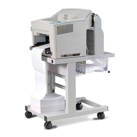
Installing the Printer and the intelligent Paper Stacker A First Look at the devices 1 Laser Printer intelligent Paper Stacker (iPS) 3 Paper shelf Tractor (Paper input) 5 Control panel Paper exit 7 Pendulum Paper exit tray 9 Castors Note: The intelligent Paper Stacker (2) – also called iPS F44 - is a special option. -
Page 23: Check Delivery Of Completeness
Installing the Printer and the intelligent Paper Stacker 1.3 Unpack the intelligent Paper Stacker - iPS F44 1.3.1 Check delivery for completeness Please check the delivery for damage. If a part is damaged, the supplier must be contacted immediately. 1.3.2 Unpack the iPS F44 –... -
Page 24: Unpacking And Installing The Printer
Installing the Printer and the intelligent Paper Stacker 1.4 Unpacking and installing the Printer The printer SOLID F44 is delivered in a package with the following label. Note: Before unpacking the SOLID F44 should be checked whether the specified mains voltage corresponds to the local power supply. Otherwise, contact the supplier. -
Page 25: Unpacking The Printer Solid F44
Installing the Printer and the intelligent Paper Stacker 1.4.2 Unpacking the Printer SOLID F44 – Remove the foam (1) by lifting off – Remove the box incl. positioning (3), (4) and (5) – Remove Image Cartridge (6) After removing the plastic foil lift the printer (2) with two persons using the transport grips (7) on the left and right side of the printer (2) and put it onto a table or onto the iPS F44. - Page 26 Installing the Printer and the intelligent Paper Stacker 1.4.3 Removing the Transport Locks of the Printer – First remove the security strips (8). – Push the latch (9) in direction of arrow and open the top cover. – At the bottom left of the printer is an additional protective strip (10). Remove the strip carefully.
-
Page 27: Installing The Image Cartridge
Installing the Printer and the intelligent Paper Stacker 1.5 Installing the Image Cartridge – Open the top cover. – Unpack the Image Cartridge (1) and shake it slowly – Remove both lock strips (2) of the Image Cartridge – Put the Image Cartridge (1) into the left and right guiding (3) and slide it to the bottom. -
Page 28: Mounting The Tear Off Bar
1.7 Align the Printer on the iPS Move the Printer SOLID F44 (1) until to the edge (3) of the iPS F44 (2). The right and left side (4) of the Printer must be flush with the iPS. -
Page 29: Mount The Pendulum At The Ips F44
Installing the Printer and the intelligent Paper Stacker 1.8 Mount the Pendulum at the iPS F44 – Loosen the pendulum (1) from the iPS F44. – Remove the right and left side covers (2) from the Pendulum (1) by removing the five screws (3). -
Page 30: Connect The Printer Solid F44 With The Ips F44
Installing the Printer and the intelligent Paper Stacker 1.9 Connect the Printer SOLID F44 with the iPS F44 – Power off the Printer. – Plug the interface cable (1) into the socket and tighten the screws. – The ground cable (2) from the iPS F44 defer to the cable shoe. -
Page 31: Open The Extensions Of The Paper Tray
Installing the Printer and the intelligent Paper Stacker The length of the pendulum (6) must also be adapted to the paper length. This is done as follows: – Loosen the thumbscrews (7). – Move the pendulum length (6), depending on the paper length up or down (the perforation of the continuous paper must be visible below the pendulum). -
Page 32: Remove Paper
1.11 Connection to a Computer or to a Network Note: The printer must be powered off! 1.11.1 SOLID F44 Parallel and Ethernet Interface The printer is equipped with an IEEE 1284 and an Ethernet 10 Base T / 100TX interface. These are located at the rear of the printer. -
Page 33: Power On/Off Switch
Installing the Printer and the intelligent Paper Stacker 1.12 Power ON/OFF Switch Ο – Make sure that the power switch of the printer is placed in the (OFF) (2) position. – Connect the printer to the mains using the power cord (1). Note: With the power ON/OFF switch (2) switches the printer’s power supply and the Stacker iPS ON or OFF. -
Page 34: Inserting Fanfold Paper
Installing the Printer and the intelligent Paper Stacker 1.13 Inserting Fanfold Paper Note: When using the printer in combination with the stacker iPS F44 the default setting for the FOLD = POSITIVE, check whether the folding points outwards behind the first page (the fold points the operator). When the folding is negative (so facing away from you), then the first page has to be separated or setting FOLD = NEGATIVE must be selected (see chapter 4 Explanation of the Individual Menu Items). - Page 35 Installing the Printer and the intelligent Paper Stacker – Open the first tractor covers (2), insert the Paper up to the second tractor and close one of the first tractor covers. – Pull out the knob (1) again in the direction of the arrow and turn the knob (1) for the fine adjustment.
-
Page 36: Printer Operation
2. Printer Operation 2.1 Control Panel READY ERROR DATA The control panel – gives information about the printer status FORM FEED ONLINE MENU CANCEL – controls various parameter settings – allows manual control of the paper handling 2.1.1 Description of the display elements ... -
Page 37: Function Keys
Printer Operation If the printer is in the OFFLINE mode status information, error messages, or menu messages are displayed. − The structure of the display of status and error messages is: OFFLINE ( 1 ) Messages Example: The printer is warming up: OFFLINE ( 1 ) WARMING UP... -
Page 38: Short Description Of Keys In The Offline Mode
Printer Operation 2.2.2 Short Description of Keys in the OFFLINE mode Display − Function [ONLINE] ONLINE − Changing to ONLINE mode − Starts data transfer − Leaving the Menu Mode Note: In the OFFLINE mode, all keys (3) and (4) have a function. These are only switched off by pressing the button [ONLINE] again. -
Page 39: Menu-Mode
Printer Operation 2.3 Menu Mode All operator selected features are accessible via the control panel and combined in the printer MENU. This feature provides: – Easy handling of configuration (language, etc.) – Quick parameter changes – Activation of test functions There are four entry points: –... - Page 40 Printer Operation Selection of functionen and parameters at a certain menu level: − Press ; the keys have a wrap around function, i.e. after the last value the first value is repeated. After selecting CHANGE PROFILE by pressing you have entered the main function level of the Menu Mode: CNG PROFILE nn (nn = 1 up to 50;...
-
Page 41: Confirm A New Selection
Printer Operation 2.3.2 Confirm a new Selection Press confirmed value is displayed with an asterisk (*) in the last position as shown in the picture before. All new values will be saved at once! Note: The Menu mode is left by pressing the [ONLINE] key. Note: All actual parameter settings can be printed with the function SELF TEST in the TEST MODE. -
Page 42: Configuring The Printer
3. Configuring the Printer 3.1 What is Configuring? This chapter describes how to use the control panel and menu to set up or configure your printer so that the printer and your computer system can communicate correctly with each other. The important menus are: −... -
Page 43: Profiler F44
Configuring the Printer – Profiler F44 The Profiler is software for editing printer profiles of SOLID F44. The contents of the 50 printer profiles (macros) are read from SOLID F44 and stored on the PC / notebook. There they can be changed and updated when needed in the printer. The program requires no installation and has a small memory footprint, so for example it can be started directly from a USB disk. -
Page 44: How To Start The Self Test
Configuring the Printer 3.2.1 How to Start the SELF TEST Display 1. Switch the printer ON ONLINE (1) (after initialization) 2. Press [ONLINE] OFFLINE (1) 3. [MENU] key OFFLINE (1) TEAR OFF FORM 4. Repeatedly pressing the OFFLINE (1) Button to select TEST MODE 5. -
Page 45: Printout Of The Profiles
Configuring the Printer Printout of the Profiles To printout the contents of all 50 Profiles use the same sequence as described in paragraph 3.2.1 How to Start the SELF TEST up to point 6. After selecting AUTO-TEST CONT, the printer starts to print all 50 Profiles. Note: The text "Default"... -
Page 46: Menu Structure
Configuring the Printer Menu Structure o start the Menu Mode, press [ONLINE] and then press [MENU]. Note: T PAPER MENU PAPER n = 1 up to 50 PAPER LENGTH LENGTH FACTOR OFFLINE (n) IMAGE WIDTH TEAR OFF FORM SELECT PROFILE ORIENTATION SELECT PROFILE LANDSCAPE MODE... -
Page 47: Menu Item Description
Configuring the Printer 3.5 Menu Item Description OFFLINE PARAMETER VALUE TEAR OFF FORMS SELECT PROFILE see below FEED N PAGES 1..16 POSITIVE | < SELECT FOLD NEGATIVE | > CHANGE PROFILE see below BASIC SETTINGS see below TEST MODE see below RESET PRINTER The following table show menu modes, submenus and parameters. -
Page 48: Paper Menu
Configuring the Printer PAPER MENU Entry Point = CHANGE PROFILE ---> PAPER MENU PARAMETER VALUE PAPER LETTER CUSTOM PAPER LENGTH 12 inch (only for CUSTOM) (Range: 3 up to 20 inch; in steps of 1⁄4 or inch) LENGTH FACTOR (only for CUSTOM) (Range: 1 up to 20 logical pages) IMAGE WIDTH 11 inch... -
Page 49: Pcl Menu
Configuring the Printer PCL-MENU Note: The PCL MENU will be displayed if the EMULATION in the GENERAL MENU is set to PCL Entry Point = CHANGE PROFIL ---> PCL-MENU PARAMETER VALUE FONT NUMBER ( Range: Font No. 0 up to 54) PITCH 10.00 (for Font No. -
Page 50: Hexdump Menu
Configuring the Printer HEXDUMP MENU The HEXDUMP MENU will be displayed if the EMULATION in the Note: GENERAL MENU is set to HEXDUMP Entry Point = CHANGE PROFILE ---> HEXDUMP MENU PARAMETER VALUE UEL COMMAND RECOGNIZE IGNORE GENERAL MENU Entry Point = CHANGE PROFILE ---> GENERAL MENU PARAMETER VALUE EMULATION... -
Page 51: Config.-Menu
Configuring the Printer CONFIG.-MENU Entry Point = BASIC SETTINGS ---> CONFIG. MENU PARAMETER VALUE 15 min (Range: 15 up to 60 minutes; steps 15 min.) POWER SAVE ALARM BELL ENGLISH DEUTSCH LANGUAGE FRANCAIS ESPANOL PROFILES ONLY MENU ACCES NONE PARALLEL ONLY * HOST CHANEL I/O EXTENSION RECAL FACTORY... -
Page 52: Clock Menu
Configuring the Printer CLOCK MENU Entry Point = BASIC SETTINGS ---> CLOCK MENU PARAMETER VALUE WEEKDAY MONDAY up to SUNDAY 1 ... 31 MONTH JANUARY up to DECEMBER YEAR 2011 ... HOUR 0 ... 24 MINUTE 0 ... 59 SECOND 0 ... -
Page 53: Info Menu
Configuring the Printer INFO MENU Entry Point = TEST MODE ---> INFO MENU PARAMETER MEANING PRINTER TYP Displays the printer model (here F44) ENGINE ID Display the firmware version of the hardware controller FIRMWARE VERS. Displays the actual PPOS Firmware Display of FPGA version CPC-FPGA VERS. -
Page 54: Explanation Of Individual Menu Items
4. Explanation of Individual Menu Items In OFFLINE mode − the different PROFILES can be programmed, − the BASIC SETTINGS can be configured, − and the printer can be set into the TEST MODE. Note: All following functions are in the OFFLINE mode selectable by using the (see also chapter 2.2 Function Keys). -
Page 55: Change Profile
Explanation of Individual Menu Items CHANGE PROFILE To change one out of 50 possible set up parameter blocks called Profiles, determining the application specific printer set up. Note: Each profile contains all print job relevant set up parameters specifying the features and functions grouped into different submenus like PAPER MENU, PCL MENU, and GENERAL MENU. -
Page 56: Menu Mode Change Profile
Explanation of Individual Menu Items 4.2 Menu Mode CHANGE PROFILE Configuration of one specific Profile. 4.2.1 Submenu PAPER MENU PAPER A choice out of three different paper sizes can be made: LETTER CUSTOM If A4 or LETTER is selected the printer automatically sets all parameters which define the allocation of the print image on a page. -
Page 57: Length Factor
Explanation of Individual Menu Items LENGTH FACTOR The length factor divides the physical paper length into an integer multiple of logical pages. A physical page is printed when its pertaining last logical page is completed with a Form Feed command. If the number of logical pages is not a multiple of the LENGTH FACTOR, the contents of the residual logical pages will remain in the printer. -
Page 58: Landscape Mode
PCL COMPATIBLE REVERSE LANDSCAPE MODE The orientation of the print image is influenced by this parameter. Setting Landscape Mode to REVERSE (default) rotates the image of LANDSCAPE to REVERSE LANDSCAPE and REVERSE LANDSCAPE to LANDSCAPE. This makes continuous pages with landscape orientation readable like a book. -
Page 59: Paper Extended
Beschreibung der einzelnen Menüpunkte PAPER EXTENDED With PAPER EXTENDED set to NO printing into the border areas of A4 and LETTER pages is not possible which is in line with the PCL5 definition. However, for compatibility to existing applications which use the border areas PAPER EXTENDED can be set to YES. -
Page 60: Toner Density
Beschreibung der einzelnen Menüpunkte TONER DENSITY This parameter allows adjusting the toner density. Possible values are: XHIGH HIGH MIDDLE (default) XLOW VER SHIFT (VERTICAL SHIFT) HOR SHIFT (HORIZONTAL SHIFT) The parameters VER SHIFT and HOR SHIFT allow to precisely position the print image vertically (-50...+50/100) and horizontally (!50...+50/100). -
Page 61: Pcl-Menu
Beschreibung der einzelnen Menüpunkte 4.2.2 PCL MENU The PCL Menu defines the parameters that are responsible for page creation and presentation of characters on a page. Note: The PCL MENU will only be displayed if EMULATION = PCL is selected in the GENERAL MENU. -
Page 62: Line Spacing
Beschreibung der einzelnen Menüpunkte Display Symbol Set ID Number (continuation) VN US Ventura US MS PUBL Microsoft Publishing MATH-8 Math-8 PS MATH PS Math VN MATH Ventura Math PI FONT Pi Font LEGAL Legal ISO-4 ISO United Kingdom ISO-6 ISO US ASCII ISO-11 ISO Swedish ISO-15... -
Page 63: Text Length
Beschreibung der einzelnen Menüpunkte TEXT LENGTH The parameter defines the number of lines on a page; exceeding this limit leads to a transition onto the next following page. Any value from 0 up to 999 can be selected; factory default value is 72. The parameter is ignored if PERF. SKIP = OFF was selected. -
Page 64: General Menu
Beschreibung der einzelnen Menüpunkte 4.2.4 GENERAL MENU In the GENERAL MENU the operating parameters for each job are fixed. EMULATION The Emulation determines the printer's set of command codes. Default emulation is PCL (PCL5E). The function HEXDUMP is useful to analyze the data received by the printer. Control codes are not executed, instead all data including command codes are printed out in hexadecimal format and as ASCII characters. -
Page 65: Menu Mode Basic Settings
Beschreibung der einzelnen Menüpunkte 4.3 Menu Mode BASIC SETTINGS 4.3.1 CONFIG. - MENU In the Configuration Menu general settings for the printer´s operation are defined. POWER SAVE The time until the power save mode is entered can be set to 15, 30, 45, 60 MIN or OFF;... -
Page 66: Host Channel
Beschreibung der einzelnen Menüpunkte HOST CHANNEL The following types are available: – PARALLEL ONLY (Default) – I/O EXTENSION The selection PARALLEL ONLY means that only the Centronics port can receive data. If I/O EXTENSION is selected only the optional channel can be used e.g. Ethernet. RECAL FACTORY By calling up RECALL FACTORY in CONFIG. -
Page 67: Test Mode
Beschreibung der einzelnen Menüpunkte 4.4 TEST MODE Within the TEST MODE general printer status information can be accessed and test printouts can be generated. The TEST MODE is split into: – TEST MENU – INFO MENU 4.4.1 Submenu TEST MENU PANEL TEST Use this point to check all Operator Panel display functions. - Page 68 Beschreibung der einzelnen Menüpunkte Typeface Pitch / Point Font # Incised901 SWC scalable I 19 Incised901 SWC Bold scalable I 20 Incised901 SWC Italic scalable I 21 OrigGaramond SWC scalable I 22 OrigGaramond SWC Bold scalable I 23 OrigGaramond SWC Italic scalable I 24 OrigGaramond SWC Bold Italic...
-
Page 69: Infomenu
Beschreibung der einzelnen Menüpunkte 4.4.2 INFO MENU In this submenu the following printer details are displayed of the Operator Panel: PRINTER TYPE Displays the printer model ENGINE ID Displays the actual Engine Firmware version. FIRMWARE VERSION Displays the current version of the operating system of the printer (PPOS, PSi Printer Operating System). -
Page 70: Maintenance
5 Maintenance Preferred Materials The following materials are recommended for use in the maintenance procedure: – Lint-free cloth – Vacuum cleaner – Pincers 5.1 Preventive Maintenance and Cleaning The user should clean the paper input area every six month. If you experience paper feed problems cleaning should be carried out more often. -
Page 71: Processing Of Paper Jam
Maintenance 5.2 Processing of Paper Jam 5.2.1 How to use this section Find out the category in which the problem occurs. The problem categories are: – Jam near tractor – Jam near Image Cartridge – Jam near fuser – Jam in the iPS F44 (Stacker) 5.2.2 Jam near tractor –... - Page 72 Maintenance – The Guide Board (3) has be rotated up to 90 degrees, then it is possible to remove it by pull it up. – Disconnect the jammed paper. – Tear off the paper in the upper part of the transportation part. –...
-
Page 73: Jam In The Ips F44
Maintenance 5.2.4 Jam in the iPS F44 (Stacker) Especially when using a narrow continuous Paper (A4 is narrower than), it is possible that the metal strips (1), for discharging static electricity, located outside of the paper. In this case, they must be set closer. The steps are as follows: –... -
Page 74: Exchange Tru (Transfer Roller Unit)
Maintenance Exchange TRU (Transfer Roller Unit) After the life of 150,000 pages the Transfer Roller Unit is an exchange by the user necessary. Note: Don´t press onto the black foam roller (6) of the TRU (7). 5.3.1 Disassembly TRU Note: The TRU is pushed for easier removal via the menu before. –... -
Page 75: Install Tru
Maintenance 5.3.2 Install TRU Note: By careful, don´t press onto the black foam roller of the TRU. This can result impairment of the print image. – Install the new TRU by lifting up the blue lever (9) again and insert the TRU on one side. -
Page 76: Troubleshooting And Diagnostics
6 Troubleshooting and Diagnostics How to Use This Section 1. Find the category to which your problem belongs. The problem categories are: – Power-related Problems – Error Messages 2. Find the symptom description that most closely matches the printer symptom. 3. -
Page 77: Status And Error Messages
Troubleshooting and Diagnostics 6.2 Status and Error Messages After self test the printer enters the ONLINE mode. In case of a failure the printer changes into the OFFLINE state and one of the following messages may appear on the display: 6.2.1 Information Messages Display That means ... - Page 78 Measure NO IC UNIT No Image Cartridge installed Insert a new Image Cartridge INVALID IC Wrong Image Cartridge Install an IC from MICROPLEX Image Cartridge used Insert a new Image Cartridge EXCHANGE IC (life 180,000 pages) (see chapter 1.5) Transfer Roller Unit used...
- Page 79 Troubleshooting and Diagnostics Display That means ... Measure Warning: The typical life cycle of After pressing [ONLINE] the the EEPROM is reached. The printer continued the print job. stacker is further fully ST. EEPROM LIFE Call service to replace the operational until a program error EEPROM occurs.
- Page 80 Troubleshooting and Diagnostics Display That means ... Measure Fan trouble 1 Cooling fan of the high Power Printer OFF and On voltage board stopped. again. SERVICE FAN n 2 Sucking fan of the high If error still there call Service voltage board stopped.
-
Page 81: Technical Data
Technical Data The technical data specified in this chapter are applicable to the printer SOLID F44. 7.1 Printer Specification Up to 44 pages per minute (Letter Landscape) Print Speed: Up to 34 pages per minute (11 inch page length) Up to 31 pages per minute (12 inch page length) 2.267 lines per minute at 6 lines per inch Resolution: 600 x 600 dpi... -
Page 82: Connectivity
Technical Data Connectivity Standard Interface and Emulations Interface: Parallel IEEE 1284 Ethernet 10BaseT / 100BaseTX USB 2.0 Emulations / PDL: HP LaserJet 4 (PCL 5e, PJL), HP – GL2 PCL / PJL Extension Fonts: 45 scalable fonts, 10 bitmap fonts Barcodes: Code 39, Code 93, Code 128, Codabar, 2/5 industrial, 2/5 interleaved, EAN 8/13 Add on 2/5, Postnet, MSI, UPC-A... -
Page 83: Control Unit
Technical Data Control Unit Processor: Power PC Data Memory: 128 MB standard 32 MB FLASH EPROM Program + Font Memory: Note: allows onside software update. Stacker Control: Supports attached intelligent Paper Stacker iPS F44 Consumables For Letter Formats (8.5 x 11 inch) at 5% toner coverage up to Imaging Cartridge: 18,000 pages Fusing Unit:... -
Page 84: Paper Specification
8 Paper Specification 8.1 Basic Theory of Operation The experiment described in this document printer SOLID F44 electro- photographically works with a laser diode. In the write process writes the laser diode by light to print the contents of electro statically to the rotating photoconductor drum in the print cartridge. -
Page 85: Environment Considerations
Paper Specification 8.3 Environmental Considerations The printer is designed to operate in a wide range of environmental conditions. For best performance, store and use fanfold paper at 19E to 23° C (68° to 73° F) and a relative humidity of 33 to 47 percent. Follow these guidelines when media is used in an environment outside the temperature and humidity ranges: –... -
Page 86: Transport Holes
Paper Specification Transport holes Note: All measurements conditioned at 23° C (68° F) and 50% RH 4 mm " 0.1 mm 0.16 inch " 0.004 inch 6 mm " 0.7 mm 0.24 inch " 0.028 inch 6 mm " 0.7 mm 0.24 inch "... -
Page 87: Perforation
Paper Specification Perforation Note: All measurements conditioned at 23E C (68° F) and 50% RH No cut in crossing area! Cutted area 3.0 to 4.0 mm (0.12 to 0.16 inch) Uncutted area 1.0 mm (0.04 inch) No cut through the edges! -
Page 88: Typical Paper Properties For Laser Printers
Paper Specification 8.4.2 Typical Paper Properties for Laser Printers Description Specifications Applicable Standard / Method curl 5mm (0.2 inch); no diagonal curl at conditioned (23 " 2)°C and (15 ± 5) % RH stability of maximum 0.8% dimension cross to in heat chamber at paper path 110°C for 20 minutes... -
Page 89: Paper / Form Properties
Paper Specification 8.4.3 Paper / Form Properties Description Specifications Applicable Standard / Method basic weight 64 to 155 g/m ± 5% DIN EN ISO 536 (17 to 41 lb) condition no callous, folds, holes, no raised parts relative humidity (40 ± 7) % at (21 " 2)°C DIN EN ISO 287 specific volume 1.3 ±... - Page 90 Paper Specification Description Specifications Applicable Standard / Method Paper length: Printer without minimum: 3 inch maximum: 20 inch Printer with iPS minimum: 7 inch maximum: 17 inch relative humidity (40 ± 7) % at (21 ± 2)°C DIN EN ISO 287 difference maximum 10% RH between humidity...
-
Page 91: Label Carrier Properties
Paper Specification 8.4.4 Label Carrier Properties Description Specifications Applicable Standard / Method specific (1.3 ± 0.2) cm /g DIN EN ISO 438 volume arch maximum 5 mm DIN 6724 break stability vertical minimum 85 N DIN 53 112 horizontal minimum 40 N crack stability minimum 150 kPa DIN EN ISO 2758... -
Page 92: Label Properties
Paper Specification 8.4.5 Label Properties Description Specifications Applicable Standard / Method condition no callous, folds, holes, no DIN 6730 raised parts specific (1.3 ± 0.2) cm /g DIN EN ISO 438 volume arch maximum 5 mm DIN 6724 break stability vertical minimum 65 N DIN 53 112... -
Page 93: Specifications
Paper Specification Description Specifications Applicable Standard / Method difference maximum 10% RH between humidity of paper and ambiance difference maximum ± 2°C between paper and room temperature curl 5mm (0.2 inch); no diagonal curl at conditioned (23 ± 2)°C and DIN 6724 (50 ±... -
Page 94: Appendix A Programming Guide
Appendix A Programming Guide The printer SOLID F44 supports the PJL Printer Job Language and PCL5 Printer Language. All the printer´s unique features and functions can be controlled by the application software via PJL or PCL5 commands. Among those functions are the following: Job Control Support using profiles see paragraph A-1.1... -
Page 95: Support Of Printer Specific Features And Functions
Appendix A Programming Guide A-1 Support of Printer Specific Features and Functions The Fanfold Laser Printer provides programming support of Printer Specific Features and Functions. These Functions are implemented with special Printer Job Language commands. The following hints show in combination with application examples how to use and program these functions: A-1.1 Profiles... -
Page 96: A-1.3 Semi Graphics Support Under Sap
Appendix A Programming Guide A-1.3 Semi graphics Support under SAP R/3 To increase the printer performance when the printer is running under SAP R/3 PSi provides a printer specific SAP R/3 device type. These device types make use of the special semi graphic line draw elements. -
Page 97: A-1.6 Conventions
Appendix A Programming Guide A-1.6 Conventions The following conventions are used in the command listings: Escape (1/B), introduces an escape sequence Introduce a PJL command Numeric parameter, or number of units that specify a distance or quantity pertaining to the escape sequence, control function or control string. -
Page 98: List Of Supported Pjl Control Functions
Appendix A Programming Guide A-2 List of Supported PJL Control Functions The Fanfold Laser Printer provides limited support of Printer Job Language (PJL). PJL topics which are described in this chapter are: Basic Rules for PJL Programming – PJL Environments –... - Page 99 Appendix A Programming Guide A-2.1.2 PJL Environments The factory default is stored in the flash memory of the printer and cannot be changed by the user After power on or after RECALL FACTORY or after @PJL INITIALIZE the printer default settings are copied from the Factory Defaults Environment into the User Default Environment.
-
Page 100: A-2.1.3 List Of Supported Pjl Commands
Appendix A Programming Guide A-2.1.3 List of Supported PJL Commands PJL COMMAND Description The COMMENT command is used for adding a line of @PJL COMMENT [?text?] information or a comment within a set of PJL commands. Defines the name and pages of a PCL print job. @PJL JOB [NAME= ?text?] NAME = file name (ASCII text) [START= #] [END = #]... - Page 101 Appendix A Programming Guide PJL COMMAND(cont.) Description @PJL RDYMSG ["text of Displays a message in the 1 line of the printer´s operator message”] panel The message length is at max. 16 characters The printer remains online @PJL RDYMSG ["”] Clear the message on the printer´s operator panel @PJL OPMSG ["text of Displays the message in the 1 line of the printer´s...
-
Page 102: A-2.1.4 List Of Supported Pjl Variable And Values
Appendix A Programming Guide PJL COMMAND(cont.) Description @PJL ECHO [ words ] Returns the ?words? to the host computer. @PJL USTATUS Allows the printer to send unsolicited status messages. Supported variables and values are: variable = value DEVICE = ON : send after status change DEVICE = VERBOSE : same as ON + PJL errors DEVICE = OFF... - Page 103 Appendix A Programming Guide PJL VARIABLE (cont.) VALUES ORIENTATIONMODE FIXED, AUTOMATIC PAPEREXTENDED NO, YES PAPERSELECT RECOGNIZE, ONLYPJL, IGNORE FUSERTEMP LOW, MIDDLE, HIGH TONERDENSITY XLOW, LOW, MIDDLE, HIGH, XHIGH; HUMIDITY NORMAL, HIGH VERSHIFT -50, -49, .., -1, 0, 1, 2, .., 50 HORSHIFT -50, -49, .., -1, 0, 1, 2, .., 50 PERSONALITY...
- Page 104 Appendix A Programming Guide The following variables can be programmed by the PJL command: @PJL DEFAULT “variable” = “value” PJL VARIABLE VALUES POWERSAVE OFF, 15, 30, 45, 60 ALARMBELL ON, OFF LANG ENGLISH, GERMAN, FRENCH, SPANISH MENUACCESS ALL, PROFILESONLY, NONE Note: These variables cannot be used by the PJL COMMAND SET.
-
Page 105: A-2.1.5 List Of Supported Pjl Variable And Values For Pcl Personality
Appendix A Programming Guide A-2.1.5 List of Supported PJL Variables and Values for PCL Personality The following variables can be programmed by the PJL commands: – @PJL SET LPARM : PCL “variable” = “value” – @PJL DEFAULT LPARM : PCL “variable” = “value” PJL VARIABLE VALUES FONTNUMBER... -
Page 106: List Of Supported Pcl5 Control Functions
Appendix A Programming Guide A-3 List of Supported PCL5 Control Functions A-3.1 Job Control Commands JOB CONTROL COMMANDS Description ESC % - 12345 X Universal Exit / Start of PJL Change to PJL Language Interpretation Mode Reset the printer like performing a Reset command Print all data received before the UEL command ESC E Reset... -
Page 107: A-3.2 Page Control Commands
Appendix A Programming Guide A-3.2 Page Control Commands PAGE CONTROL Description COMMANDS ESC & l # A Page Size Definition of the paper size and in turn of the logical page size. Parameters: # = 2 : Letter # = 26 : A4 # = 101 : Custom (Private Command) ESC &... - Page 108 Appendix A Programming Guide A-3.3 Cursor Positioning Commands CURSOR POSITIONING Description COMMANDS ESC & a # C Horizontal Position in Columns ESC * p # X Horizontal Position in PCL Units ESC & a # H Horizontal Position in Decimal points ESC &...
-
Page 109: A-3.4 Font Selection Commands
Appendix A Programming Guide A-3.4 Font Selection Commands Description FONT SELECTION COMMANDS ESC ( ID Symbol Set , primary ID = Code for Symbol Set, see Chapter 4 Explanation of Individual Items and here point SYMBOL SETS or a Printout of PCL TYPEFACE LIST ESC ( s # P Spacing, primary... -
Page 110: A-3.5 Font Management Commands
Appendix A Programming Guide A-3.5 Font Management Commands FONT MANAGEMENT COMMANDS Description ESC & d # D Enable Underline # = 0 : Fixed position # = 3 : Floating position ESC & d @ Disable Underline ESC & p # X [data] Transparent Print Data ESC * c # D Assign Font ID #... -
Page 111: A-3.6 Macro Control Commands
Appendix A Programming Guide A-3.6 Macro Control Commands MACRO CONTROL COMMANDS Description ESC & f # Y Macro ID ESC & f # X Macro Control # = 0 : Start macro definition (last ID specified) # = 1 : Stop macro definition # = 2 : Execute macro (last ID specified) # = 3... -
Page 112: A-3.7 Graphic Commands
Appendix A Programming Guide A-3.7 Graphic Commands GRAPHIC COMMANDS Description ESC * v # N Source Transparency Mode ESC * v # O Pattern Transparency Mode ESC * c # G Area Fill ID ESC * v # T Select Current Pattern ESC * c # W [data] Define User Defined Pattern ESC * p # R... -
Page 113: Support Of Semi Graphics For Sap/R3
Appendix A Programming Guide Note: For detailed information see HP PCL 5 Technical Reference Manual. A-3.8 Status Read Back Commands STATUS READ BACK COMMANDS Description ESC * s # T Set Status Read back Location Type ESC * s # U Set Status Read back Location Unit ESC * s # I Set Status Read back Entity... -
Page 114: Barcode Programming
Appendix A Programming Guide ESC(ON(s0p16.67h0s0b4099T A-5 Barcode Programming A-5.1 Resident Barcode Font Code 39 HP Compatible The barcode Code 39 is integrated as two bitmapped fonts into the Operating System for the printer as resident printer font. These bitmapped fonts can be used compatible to the cartridge implementation from Hewlett Packard Barcode &... - Page 115 Appendix A Programming Guide A-5.1 Intelligent Mail® Barcode Fonts (IMB) The barcode IMB is integrated as two bitmapped fonts into the Operating System for the printer as resident printer font. Two IMB resident barcode fonts are available, a standard version with a height of 10.49 points and a compact version with a height of 9.09 points.
-
Page 116: A-5.2 Resident Barcodes Controlled By Private Command Sequences
Appendix A Programming Guide A-5.3 Resident Barcodes Controlled by Private Command Sequences Introduction Barcodes are programmed in three subsequent steps: 1. Select a barcode type and define the barcode specific parameter set of: – height – module width – ratio of bars to spaces –... -
Page 117: Barcode Print Orientation
Appendix A Programming Guide A-5.4 Programming Programming of the resident barcodes is achieved by means of six new control sequences added to the PCL5 emulation. The print position and print orientation of a barcode is controlled by standard PCL5 commands. Barcode print position Printing of any barcode starts at the current actual cursor position. -
Page 118: Barcode Type
Appendix A Programming Guide Barcode type This command selects a barcode type: ESC * z P1 V default = 0 P1 = 0 Code 39 P1 = 1 2 of 5 industrial P1 = 2 reserved P1 = 3 reserved P1 = 4 2 of 5 interleaved P1 = 102... -
Page 119: Barcode Height
Appendix A Programming Guide Barcode height This command defines the height of the actual selected barcode: ESC * z P1 H P1 = height in PCL units For every barcode type an individual value is stored. The default height value for barcode is 0.5 inch (P1 = 150) except EAN, UPC and Postnet. -
Page 120: Barcode Text Control
Appendix A Programming Guide Barcode text control This command controls the optional printing of barcode data as an added text string. ESC * z P1 Q P1 = 0 disable text P1 = 1 text above barcode with OCR-B font P1 = 2 text below barcode with OCR-B font (default) P1 = 3... -
Page 121: Barcode Ratio
Appendix A Programming Guide Barcode ratio This command selects one of the available ratios between wide and narrow bars (spaces). ESC * z P1 O P1 = 2.0 ; 2.5 ; 3.0 ; default is 2.5 Note: This command is not applicable to all barcodes; refer to table below. Default values for module width and ratio: Module width Ratio... -
Page 122: Start And Stop Characters
Appendix A Programming Guide Start and Stop characters For barcode types EAN, UPC, Code 93, Code 128 and Postnet the printer automatically adds start and stop characters. For barcode type Code 39, 2 of 5 industrial and 2 of 5 interleaved the printer adds start and stop characters only if they are not generated by the system. -
Page 123: Of 5 Industrial
Appendix A Programming Guide A-5.5 Barcode Programming Examples Example for Code 39 type = Code 39: ESC * z 0 V height = 0.6 inch ESC * z 180 H text = OCR-B above ESC * z 1 Q data = CODE 39 ESC * z <... -
Page 124: Ean 8 Sc2
Appendix A Programming Guide Example for 2 of 5 interleaved type = 2 of 5 interleave: ESC * z 4 V position = X=500; Y=500 ESC * p 5 0 0 x 5 0 0 Y orientation = 90° ESC & a 9 0 P text = actual font below ESC * z 4 Q... - Page 125 Appendix A Programming Guide Example for EAN 8 SC6 add 2 type = EAN 8 SC6 ESC * z 1 0 6 V orientation = 270° ESC & a 2 7 0 P text = actual font below ESC * z 4 Q data = 4 0 1 2 3 4 5 5 1 2 ESC * z 1 0 Z 4 0 1 2 3 4 5 5 1 2...
-
Page 126: Ean 13 Sc2
Appendix A Programming Guide Example for EAN 13 SC2 type = EAN 13 SC2: ESC * z 1 2 2 V orient. = 180° ESC & a 1 8 0 P text = OCR-B below ESC * z 2 Q data = 4 1 2 3 4 5 6 7 8 9 0 1 8 ESC * z 1 3 Z 4 1 2 3 4 5 6 7 8 9 0 1 8... -
Page 127: Code 128
Appendix A Programming Guide Example for Code 128 act. font = Ribbon SWC 20 Pt ESC ( s 1 p 2 0 v 1 s 0 b 4 1 1 6 T type = Code 128: ESC * z 2 1 0 V orient. -
Page 128: Postnet
Appendix A Programming Guide Example for POSTNET type = POSTNET ESC * z 2 0 0 V data = 123456789 ESC * z < 123456789 > Z CR LF LF 0D 0A 0A Mark Pollmann CR LF Mark Pollmann 0D 0A 101 Main St CR LF 101 Main St 0D 0A Anytown US... -
Page 129: Datamatrix
Appendix A Programming Guide EXAMPLE for DATAMATRIX type = DATAMATRIX ESC * z 2 3 0 V module width = 0,423 mm (5/300”) ESC * z 5 S position = X=500, Y=500 ESC * p 5 0 0 x 5 0 0 Y height = 32 modules ESC * z 3 2 H... -
Page 130: Usps Intelligent Mail® Barcode Imb
Appendix A Programming Guide At system start and after a restart of the interpreter the module width will be set to 5, the width will be 52 and the height 0. This leads to a default selected barcode of 52 x 52 will a module size of 0,432 mm. Example for USPS Intelligent Mail®... -
Page 131: Appendix B Symbol Sets
Symbol Sets Appendix B Roman-8 Display: ROMAN-8 ID Number: 8U... -
Page 132: Iso 8859/1 Latin 1
Symbol Sets Appendix B ISO 8859/1 Latin 1 Display: ISO L1 ID Number: 0N... -
Page 133: Iso 8859/2 Latin 2
Symbol Sets Appendix B ISO 8859/2 Latin 2 Display: ISO L2 ID Number: 2N... -
Page 134: Iso 8859/9 Latin 5
Symbol Sets Appendix B ISO 8859/9 Latin 5 Display: ISO L5 ID Number: 5N... -
Page 135: Iso 8859/15 Latin 9
Symbol Sets Appendix B ISO 8859/15 Latin 9 Display: ISO L9 ID Number: 9N... -
Page 136: Pc-8 Code Page 437
Symbol Sets Appendix B PC-8 Code Page 437 Display: PC-8 ID Number: 10U... -
Page 137: Danish / Norwegian
Symbol Sets Appendix B PC-8 Danish/Norwegian Display: PC-8 DN ID Number: 11U... -
Page 138: Multilingual
Symbol Sets Appendix B PC-850 Multilingual Display: PC-850 ID Number: 12U... -
Page 139: Pc-852 Latin2
Symbol Sets Appendix B PC-852 Latin 2 Display: PC-852 ID Number: 17U... -
Page 140: Pc-858 Multilingual
Symbol Sets Appendix B PC-858 Multilingual Display: PC-858 ID Number: 13U B-10... -
Page 141: Pc-Turkish
Symbol Sets Appendix B PC-Turkish Display: PC-8 TK ID Number: 9T B-11... -
Page 142: Windows 3.1 Latin 1
Symbol Sets Appendix B Windows 3.1 Latin 1 Display: WIN L1 ID Number: 19U B-12... -
Page 143: Windows 3.1 Latin 2
Symbol Sets Appendix B Windows 3.1 Latin 2 Display: WIN L2 ID Number: 9E B-13... - Page 144 Symbol Sets Appendix B Windows 3.1 Latin 5 Display: WIN L5 ID Number: 5T B-14...
-
Page 145: Desktop
Symbol Sets Appendix B Desktop Display: DESKTOP ID Number: 7J B-15... - Page 146 Symbol Sets Appendix B PS text Display: PS TEXT ID Number: 10J B-16...
-
Page 147: Ventura International
Symbol Sets Appendix B Ventura International Display: VN INTL ID Number: 13J B-17... -
Page 148: Ventura Us
Symbol Sets Appendix B Ventura US Display: VN US ID Number: 14J B-18... -
Page 149: Microsoft Publishing
Symbol Sets Appendix B Microsoft Publishing Display: MS PUBL ID Number: 6J B-19... -
Page 150: Math-8
Symbol Sets Appendix B Math-8 Display: MATH-8 ID Number: 8M B-20... - Page 151 Symbol Sets Appendix B PS Math Display: PS MATH ID Number: 5M B-21...
-
Page 152: Ventura Math
Symbol Sets Appendix B Ventura Math Display: VN MATH ID Number: 6M B-22... - Page 153 Symbol Sets Appendix B PI Font Display: PI FONT ID Number: 15U B-23...
-
Page 154: Legal
Symbol Sets Appendix B Legal Display: LEGAL ID Number: 1U B-24... -
Page 155: Iso United Kingdom
Symbol Sets Appendix B ISO United Kingdom Display: ISO-4 ID Number: 1E B-25... -
Page 156: Iso Us Ascii
Symbol Sets Appendix B ISO US ASCII Display: ISO-6 ID Number: 0U B-26... -
Page 157: Iso Swedish
Symbol Sets Appendix B ISO Swedish Display: ISO-11 ID Number: 0S B-27... -
Page 158: Iso Italian
Symbol Sets Appendix B ISO Italian Display: ISO-15 ID Number: 0I B-28... -
Page 159: Iso Spanish
Symbol Sets Appendix B ISO Spanish Display: ISO-17 ID Number: 2S B-29... -
Page 160: Iso German
Symbol Sets Appendix B ISO German Display: ISO-21 ID Number: 1G B-30... -
Page 161: Iso Norwegian
Symbol Sets Appendix B ISO Norwegian Display: ISO-60 ID Number: 0D B-31... -
Page 162: Iso French
Symbol Sets Appendix B ISO French Display: ISO-69 ID Number: 1F B-32... -
Page 163: Windows 3.0 Latin 1
Symbol Sets Appendix B Windows 3.0 Latin 1 Display: WIN 3.0 ID Number: 9U B-33... -
Page 164: Windows 3.0 Baltic
Symbol Sets Appendix B Windows 3.0 Baltic Display: WIN BALTIC ID Number: 10L B-34... -
Page 165: Symbol
Symbol Sets Appendix B Symbol Display: none ID Number: 19M Note: This Symbol Set is only addressable via a PCL Command. B-35... -
Page 166: Windings
Symbol Sets Appendix B Windings Display: none ID Number: 579L Note: This Symbol Set is only addressable via a PCL Command. B-36... -
Page 167: Order Numbers
Order Numbers Appendix C Image Cartridge (Druck-Kartusche) 8709 003 34001 Transfer Roller Unit (TRU) 8709 003 34002...
Need help?
Do you have a question about the SOLID F44 and is the answer not in the manual?
Questions and answers
How to install Solid F44 printer driver?