Table of Contents
Advertisement
Quick Links
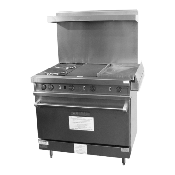
E36SLC MODEL SHOWN
This Manual is prepared for the use of trained Vulcan Service
Technicians and should not be used by those not properly qualified.
If you have attended a Vulcan Service School for this product, you
may be qualified to perform all the procedures described in this
manual.
This manual is not intended to be all encompassing. If you have not
attended a Vulcan Service School for this product, you should read,
in its entirety,
determine if you have the necessary tools, instruments and skills
required to perform the procedure. Procedures for which you do not
have the necessary tools, instruments
performed by a trained Vulcan Service Technician.
Reproduction or other use of this Manual, without the express
written consent of Vulcan, is prohibited.
For additional information on Vulcan-Hart Company or to locate an authorized parts
and service provider in your area, visit our website at www.vulcanhart.com.
A product of VULCAN-HART
SERVICE MANUAL
ELECTRIC RESTAURANT
E36LC SERIES
- NOTICE -
the repair procedure you wish to perform
RANGES
to
and skills should be
Louisville, KY 40201-0696
Form 25297 (July 2008)
ML-136624
Advertisement
Table of Contents

Related Manuals for Vulcan-Hart E36LC SERIES


Summary of Contents for Vulcan-Hart E36LC SERIES
- Page 1 Reproduction or other use of this Manual, without the express written consent of Vulcan, is prohibited. For additional information on Vulcan-Hart Company or to locate an authorized parts and service provider in your area, visit our website at www.vulcanhart.com. A product of VULCAN-HART...
-
Page 2: Table Of Contents
E36LC SERIES ELECTRIC RESTAURANT RANGES TABLE OF CONTENTS GENERAL ................3 Introduction . -
Page 3: General
E36LC SERIES ELECTRIC RESTAURANT RANGES - GENERAL GENERAL INTRODUCTION CLEANING This manual is for the Vulcan Restaurant Series Refer to the Instruction Manual for specific cleaning Electric Range equipped with convection oven. instructions. Procedures in this manual will apply to all models TOOLS unless specified. -
Page 4: Removal And Replacement Of Parts
E36LC SERIES ELECTRIC RESTAURANT RANGES - REMOVAL AND REPLACEMENT OF PARTS REMOVAL AND REPLACEMENT OF PARTS COVERS AND PANELS RANGE TOPS Control Panel Remove screws securing backsplash to frame. Pull out or remove crumb tray. Remove screws in top corners of control panel. -
Page 5: Blower Wheel
E36LC SERIES ELECTRIC RESTAURANT RANGES - REMOVAL AND REPLACEMENT OF PARTS Pull blower into oven cavity. Lift the range top being removed. Remove two set scews from blower wheel hub. Disconnect the electrical connections. Reverse procedure to install. Check range for proper operation. -
Page 6: Blower Motor
E36LC SERIES ELECTRIC RESTAURANT RANGES - REMOVAL AND REPLACEMENT OF PARTS BLOWER MOTOR Remove blower wheel as outlined under BLOWER WHEEL. Remove nuts securing mounting plate to motor. Loosen nuts while holding "J" hooks from rotating. NOTE: One nut will be right hand threaded and the other will be left hand threaded. -
Page 7: Door Mechanism Components
E36LC SERIES ELECTRIC RESTAURANT RANGES - REMOVAL AND REPLACEMENT OF PARTS Remove inside door bolts. DOOR MECHANISM COMPONENTS Remove kick panel as outlined under COVERS AND PANELS. Pinch a rag in the door to prevent the door from falling open during procedure. -
Page 8: Door Switch
E36LC SERIES ELECTRIC RESTAURANT RANGES - REMOVAL AND REPLACEMENT OF PARTS Remove bell crank pins and bell cranks. Disconnect electrical wiring from switch. Reverse procedure to install. Reverse procedure to install. Check range for proper operation. Check range for proper operation. -
Page 9: French Plate
E36LC SERIES ELECTRIC RESTAURANT RANGES - REMOVAL AND REPLACEMENT OF PARTS FRENCH PLATE Remove french plates as outlined under RANGE TOPS. Remove bolts holding mounting bracket to the french plate assemblies. Remove screw securing heating element and pull element out to expose lead wire connections. -
Page 10: Hot Top
E36LC SERIES ELECTRIC RESTAURANT RANGES - REMOVAL AND REPLACEMENT OF PARTS Remove french plate. Reverse procedure to install. Bend hooks in slightly, then remove electrical Check range for proper operation. connections. HOT TOP Remove hot top as outlined under RANGE TOPS. -
Page 11: Griddle Heating Element
E36LC SERIES ELECTRIC RESTAURANT RANGES - REMOVAL AND REPLACEMENT OF PARTS GRIDDLE HEATING ELEMENT NOTE: 12" griddle shown. Remove griddle as outlined under RANGE TOPS. Remove nuts and washers to disconnect element wiring. Remove nuts securing griddle element holding clamps. -
Page 12: Oven Thermostat
E36LC SERIES ELECTRIC RESTAURANT RANGES - REMOVAL AND REPLACEMENT OF PARTS OVEN THERMOSTAT Remove thermostat knob. Remove thermostat mounting screws. Remove left range top as outlined under RANGE TOPS. Pull capillary tube and thermostat bulb through roof of oven cavity. -
Page 13: Griddle And Hot Top Thermostats
E36LC SERIES ELECTRIC RESTAURANT RANGES - REMOVAL AND REPLACEMENT OF PARTS GRIDDLE AND HOT TOP THERMOSTATS Remove thermostat knob. Remove thermostat mounting screws. HOT TOP SHOWN NOTE: See GRIDDLE HEATING ELEMENT to access griddle thermostat bulb. Remove thermostat bulb from clamp. -
Page 14: Infinite Switch
E36LC SERIES ELECTRIC RESTAURANT RANGES - REMOVAL AND REPLACEMENT OF PARTS INFINITE SWITCH ROCKER SWITCH Pull off infinite switch knob. Open control panel as outlined under COVERS AND PANELS. Remove washer nut from applicable infinite switch stem. Disconnect rocker switch electrical connections noting their locations. -
Page 15: Indicator Lights
E36LC SERIES ELECTRIC RESTAURANT RANGES - REMOVAL AND REPLACEMENT OF PARTS INDICATOR LIGHTS MOTOR CONTACTOR (480V ONLY) Open control panel as outlined under COVERS Remove contactor box cover. AND PANELS. Disconnect all electrical connections to the Disconnect indicator light electrical connections contactor noting their locations. -
Page 16: Service Procedures And Adjustments
E36LC SERIES ELECTRIC RESTAURANT RANGES - SERVICE PROCEDURES AND ADJUSTMENTS SERVICE PROCEDURES AND ADJUSTMENTS Certain procedures in this section require electrical test or measurements while power is applied to the machine. Exercise extreme caution at all times. If test points are not easily accessible, disconnect power and follow lockout / tagout procedures, attach test equipment and reapply power to test. -
Page 17: Griddle Thermostat Calibration
E36LC SERIES ELECTRIC RESTAURANT RANGES - SERVICE PROCEDURES AND ADJUSTMENTS Turn adjustment screw CW to GRIDDLE THERMOSTAT increase and CCW to decrease CALIBRATION temperature. NOTE: A 1/4 turn equals 35°F change. Clean the temperature test site, then place temperature tester surface mount probe there. -
Page 18: Heat Switch Test (480V)
E36LC SERIES ELECTRIC RESTAURANT RANGES - SERVICE PROCEDURES AND ADJUSTMENTS Turn adjustment screw CW to DOOR ADJUSTMENT increase and CCW to decrease temperature. NOTE: Door is in adjustment when it closes on its own when held open 5 inches and comes to rest NOTE: A 1/4 turn equals 35°F change. -
Page 19: Heating Element Test
E36LC SERIES ELECTRIC RESTAURANT RANGES - SERVICE PROCEDURES AND ADJUSTMENTS If unable to check current draw, a HEATING ELEMENT TEST resistance check may indicate a malfunctioning element. Turn power ON and set temperature control to the highest setting. Disconnect electrical supply. -
Page 20: Electrical Operation
E36LC SERIES ELECTRIC RESTAURANT RANGES - ELECTRICAL OPERATION ELECTRICAL OPERATION COMPONENT FUNCTION Thermostat ....Regulates temperature of oven cavity, griddle, and hot top. 3 Heat Switch .... -
Page 21: Oven Sequence Of Operation
E36LC SERIES ELECTRIC RESTAURANT RANGES - ELECTRICAL OPERATION 480V OVEN SEQUENCE OF Conditions OPERATION Unit connected to supply voltage. 208/240V Thermostat OFF. Conditions Rocker switch OFF. Unit connected to supply voltage. Door switch closed. Thermostat OFF. Oven at room temperature. -
Page 22: Wiring Diagrams
E36LC SERIES ELECTRIC RESTAURANT RANGES - ELECTRICAL OPERATION WIRING DIAGRAMS E36LC (208, 240V) Wiring Diagram F25297 (July 2008) Page 22 of 28... - Page 23 E36LC SERIES ELECTRIC RESTAURANT RANGES - ELECTRICAL OPERATION Page 23 of 28 F25297 (July 2008)
- Page 24 E36LC SERIES ELECTRIC RESTAURANT RANGES - ELECTRICAL OPERATION E36LC (480V) Wiring Diagram F25297 (July 2008) Page 24 of 28...
- Page 25 E36LC SERIES ELECTRIC RESTAURANT RANGES - ELECTRICAL OPERATION Page 25 of 28 F25297 (July 2008)
- Page 26 E36LC SERIES ELECTRIC RESTAURANT RANGES - ELECTRICAL OPERATION 208V & 240V Range Top Wiring Diagrams F25297 (July 2008) Page 26 of 28...
- Page 27 E36LC SERIES ELECTRIC RESTAURANT RANGES - ELECTRICAL OPERATION 480V Range Top Wiring Diagrams Page 27 of 28 F25297 (July 2008)
-
Page 28: Troubleshooting
E36LC SERIES ELECTRIC RESTAURANT RANGES - TROUBLESHOOTING TROUBLESHOOTING Oven SYMPTOM POSSIBLE CAUSES No heat, blower inoperative. 1. Main breaker open. 2. Thermostat malfunction. 3. Rocker switch open. 4. Contactors malfunctioning (480V). 5. Oven door switch open. 6. Heaters inoperative. 7. Transformer malfunction (480V).
Need help?
Do you have a question about the E36LC SERIES and is the answer not in the manual?
Questions and answers