Advertisement
Quick Links
INSTRUCTION MANUAL
GENERAL DESCRIPTION
The Hy-Gain Model 216 SAT is a high-perfor-
mance "OSCAR" (Orbiting Satellite Carrying
Amateur Radio) satellite antenna for the 145.8 -
146.0 MHz frequency band. It features
polarization switching circuity for manual selec-
tion of either Right Hand Circular Polarization
(RHCP) or Left Hand Circular Polarization
(LHCP). This flexible design is suitable for
worldwide applications with any of the amateur
satellites having either an uplink or downlink in
the 145.8 - 146.0 MHz frequency range, such as
AO-10, FO-12, AO-13, DO-17, AO-16, LO-19,
U O-22, KO-23, RS-10, RS-11, RS-12, RS-13,
etc. These include modes A, B, J, JA, JD, JL,
KA, KT, and T.
It is also usable over the entire 2-meter band,
144-148 MHz; and could be used with future
satellites placed near 144.5 MHz, or with ter-
restrial modes such as repeaters and SSB/CW
DX. The vertical and horizontal sets of elements
may he fed with separate feedlines for total
flexibility.
Boom Length............................................................................................168.75 in. (429 cm)
Maximum Boom O.D. .......................................................................1.25 in. (32 mm)
Turning Radius (Max) .................................:..............................................8.ft. (2.44 m)
Total Number of Elements .......................................................................................16
Longest Element .....................................................................................39.5 in. (100 cm)
Wind Survival........................................... .......................................80 mph (128.7 km/h)
Mast/Boom Diameter Accepted
Wind Area............................................................................................1.1 sq. ft. (.102 sq. m)
Net Weight............................................................ ............................7 lbs.3 oz. (3.26 kg)
Stacking Distance (min).............................................'....82 in. (2.08
Model No. VB-216SAT
2-Meter OSCAR Satellite Antenna
Model 216 SAT
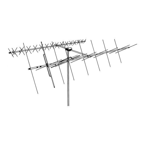
The 216 SAT Antenna features 16 elements
(total) on a 2.1 wavelength boom. Each set of 8
elements is designed to give 10.7 dBd gain based
on a quasi-logarithmic tapering of element
spacings. This design also gives a very clean
pattern, with very small sidelobes. The 216 SAT
also features high efficiency "T" matched driven
elements for easy assembly and high gain. True
R F, 50 ohm switching relays are rated at 200
watts PEP and contribute to improved VSWR.
Feedpoints are encapsulated for long life in all
types of climates. Most hardware is stainless
steel including the element retaining rings
(pushnuts). All insulators are UV protected. The
coaxial assembly is made from high-quality
Polytetrafluoethylene (PTFE) dielectric and
Fluorinated Ethylene Propylene (FEP) jacketed
coaxial cable.
The 216 SAT "OSCAR" beam can be used with
the Hy-Gain 70-30 SAT 70 cm OSCAR Beam
and the 217S, fiberglass, 5 foot boom, or it can
be used with other commercial or "homebrew"
"OSCAR" antennas. The 216 SAT antennas may
be stacked for more gain.
SPECIFICATIONS
Mechanical
............................. 1.250-1.625 in. (32 mm - 41 mm)
m)
(1.0 wavelength)
Advertisement

Subscribe to Our Youtube Channel
Related Manuals for Hy-Gain VB-216SAT


Summary of Contents for Hy-Gain VB-216SAT
- Page 1 GENERAL DESCRIPTION The 216 SAT Antenna features 16 elements (total) on a 2.1 wavelength boom. Each set of 8 The Hy-Gain Model 216 SAT is a high-perfor- elements is designed to give 10.7 dBd gain based mance "OSCAR" (Orbiting Satellite Carrying on a quasi-logarithmic tapering of element Amateur Radio) satellite antenna for the 145.8 -...
-
Page 2: Boom Assembly
One nut driver should have a hollow handle. PREPARATION FOR ASSEMBLY This can be used for pushing on the pushnuts. FOR OUR OVERSEAS CUSTOMERS: If you Standard wrenches or adjustable wrenches use the Metric System, see the American-to- may also be used in place of the nut drivers. Metric Conversion Table in the rear of this manual. - Page 3 Figure 1 Boom Assembly...
- Page 4 After assembly, the boom-to-mast bracket may ASSEMBLY OF OTHER ELEMENTS be rotated on the boom so that after mounting, the elements are in an "X" configuration. Select the two reflector elements, 3/16" x 39 Securely tighten the 1/4"-20 x 3/4" hardware. 1/2"...
- Page 5 Slide another element insulator over the other Select one each of elements D1 and D2. Iden- tify these elements by the length and color end of the reflectors and push it onto each element until it seats into the mounting hole. bands listed in Table 1.
- Page 6 Figure 3 Assembly of Directors to Boom ATTACHMENT OF COAX ASSEMBLY Select the remaining elements - D2, D3, D4, D5 and D6. Install these elements on the front and Select the coax/circularity-switch assembly mid-boom sections in the remaining holes in the (Item 17), the No.
- Page 7 Use black electrical tape, and secure this The other coaxial cable coming from the coupler tube should go around the boom and coaxial cable to the boom on both sides of the loop backwards to attach its terminals to the rear D 1 element.
- Page 8 NOTE: Looking at rear end of boom and encap- sulated feed points. Figure 5 Feedpoint Orientation for LHCP in the Unswitched Mode NOTE: Looking at rear end of boom and encap- sulated feed points. Figure 6 Feedpoint Orientation for RHCP in the Unswitched Mode Either LHCP or RHCP will result if these at- NOTE: To achieve LHCP in the unswitched...
-
Page 9: Installation
Table 2 VSWR Chart INSTALLATION NOTE: If you plan to use large diameter, The 216 SAT OSCAR Beam may be center heavy coaxial cable or if it is likely that the mounted, and a fiberglass or other type of cables may accumulate ice, you will need to nonconducting boom must be used to achieve adjust the position of the boom-to-mast circular polarity. - Page 10 PARTS LIST Item Part No. Description 160067 Reflector, 3/16" x 39 1/2" ..............2 160068 D 1, 3/16" x 35 1/2" ................2 160069 D2, 3/16" x 35 1/4"................2 160070 D3, 3/16" x 35" ..................2 160071 D4, 3/16" x 34 3/4..................2 160072 D5, 3/16"...
-
Page 11: Parts List
PARTS LIST Item Part No. Description 877887 Parts Pack 216S - Hardware (Continued) 555747 Nut, hex, 5/16"-18..……............4 562961 Lockwasher, 1/4" internal..............8 564792 Lockwasher, split, 5/16"..............8 565697 Lockwasher, #10 internal .............20 500185 Bolt, #8-32 x 1/2"................2 560035 Lockwasher, #8 internal ..............2 550063 Nut, #8-32, hex.................2 500157...
Need help?
Do you have a question about the VB-216SAT and is the answer not in the manual?
Questions and answers