Table of Contents
Advertisement
Quick Links
308 Industrial Park Road
Starkville, MS 39759 USA
Ph: (662 ) 323-9 538 FAX: (662 ) 323-
INSTRUCTION MANUAL
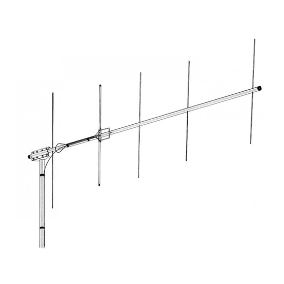
General Description
This antenna is a 5-element, 2-meter beam op-
timum spaced on a 75" boom. It features high
forward gain and an excellent front-to-back ratio.
The antenna is end mounted giving it the ad-
vantage of no mast decoupling and a broad
frequency response. This antenna now uses stain-
less steel hardware in most locations except for the
U-bolts. Also, this antenna now features a NEW
boom-to-mast bracket that fits up to a mast
diameter of 2 1/16 inches.
Boom Length
Longest Element
Net Weight
Turning Radius (Max)
Wind Survival
Mast Diameter
Boom Diameter
Wind Area
Gain (Average)
Front-to-Back Ratio
Maximum SWR
Band Width
Maximum Power
Impedance
Half-Power Beam Width
Stacking Distance
Model VB-25FM
2-Meter 5 Elements Beam
SWR and Feedline
The 25FM antenna has an input impedance of 200
ohms. The supplied balun matches the input to 50
ohms. If you are using transmission line with a
characteristic impedance other than 50 ohms or
200 ohms, a matching device must be made. Refer
to any current Amateur Handbook for information
on constructing a matching device.
Specifications
Mechanical
Electrical
75" (1905 mm)
39 5/8" (1006 mm)
2.9 lbs (1.3 kg)
73" (1854 mm)
80 mph (129 kmph)
1 5/8" to 2 1/16" O.D. (41mm to 52mm)
1 ¼" O.D. (32mm)
0.585 sq. ft (.054 m^2) (horizontal)
0.740 sq. ft (.0688 m^2) (vertical)
11.3 dBi (9 dBd)
250 Watts continuous, 500 Watts P.E.P
50 ohms (with balun)
60 degrees (vertical polarization)
45 degrees (horizontal polarization)
82" (2083 mm) minimum
20 dB
2:1
4 MHz
Advertisement
Table of Contents

Related Manuals for Hy-Gain VB-25FM


Summary of Contents for Hy-Gain VB-25FM
-
Page 1: Specifications
Model VB-25FM 308 Industrial Park Road 2-Meter 5 Elements Beam Starkville, MS 39759 USA Ph: (662 ) 323-9 538 FAX: (662 ) 323- INSTRUCTION MANUAL SWR and Feedline General Description The 25FM antenna has an input impedance of 200 This antenna is a 5-element, 2-meter beam op- ohms. - Page 2 Item Description Tube, Driven Element, aluminum, 7/16" x 17 1/4" Tube, R1, aluminum, 3/16" x 39 5/8" Tube, D1, aluminum, 3/16" x 36 7/8" Tube, D2, aluminum, 3/16" x 353/4" Tube, D3, aluminum, 3/16" x 35 3/8" Figure 1 Overall View and Boom Detail Tuning NOTE: The Driven and Parasitic Elements are...
- Page 3 Figure 2B Driven Element Figure 2A VSWR for Both Vertical and Horizontal Cutting Chart Polarization Stacking The two phasing lines coming from the two an- This antenna can be easily stacked for ap- tennas to the "T" connector can be any odd proximately 3 dB more gain each time the multiple of 1/4 wavelength in the 75 ohm trans- number of yagi is doubled.
- Page 4 The feedline impedance is for 50 ohms (RG- NOTE: The boom-to-mast bracket may be 213/U). For detailed information on stacking placed between the Driven Element and D1 more than two yagis, please consult a current when stacking two antennas. Amateur Handbook. Figure 4 Phasing Line Cutting Dimensions Installation...
- Page 5 Item Description Description Tube, Boom, aluminum, 11/4 x 75" Bolt, hex head, 1/4"-20 x Clamp, Boom-to-Mast Nut, hex, 5/16"-18 Backup Plate, Boom-to-Mast Nut, hex, 1/4"-20 Caplug, 11/4" Lockwasher, split, 5/16" U-Bolt, 5/16"-18 x 3 5/8" Lockwasher, internal, 1/4" Figure 5 Boom-to-Mast Clamp Assembly Item No.
- Page 6 Item Description Description Beta Rod, 3" Bolt, hex head, #10-24 x Balun Assembly Bolt hex head, #10-24 x 11/2" Insulator (Driven Element-to-Boom) Nut, hex, #10-24 Beta Clip Lockwasher, internal, #10 Caplug, 7/16" Figure 5-Detail B Driven Element, Beta Match and Balun Assembly Place a #10-24 x 11/2"...
-
Page 7: Parts List
NOTE: If 50 ohm coaxial cable is used to feed the antenna, select the supplied balun at this Use the #10 x 3/8" screw (Item No. 20) to time. fasten the beta rod shorting clip over the beta rod, as shown in Figure 5, Detail B. Use the # 10-24 x 21/2"... -
Page 8: Limited Warranty
Hy-Gain Warrants to the original owner of this product, if manufactured by Hy-Gain and purchased from an authorized dealer or directly from Hy-Gain to be free from defects in material and workmanship for a period of 12 months for rotator products and 24 months for antenna products from date of purchase provided the following terms of this warranty are satisfied.
Need help?
Do you have a question about the VB-25FM and is the answer not in the manual?
Questions and answers