Advertisement
Table of Contents
308 Industrial Park Road
Starkville, MS 39759 USA
Ph: (662) 323-9538 FAX: (662) 323-
INSTRUCTION MANUAL
GENERAL DESCRIPTION
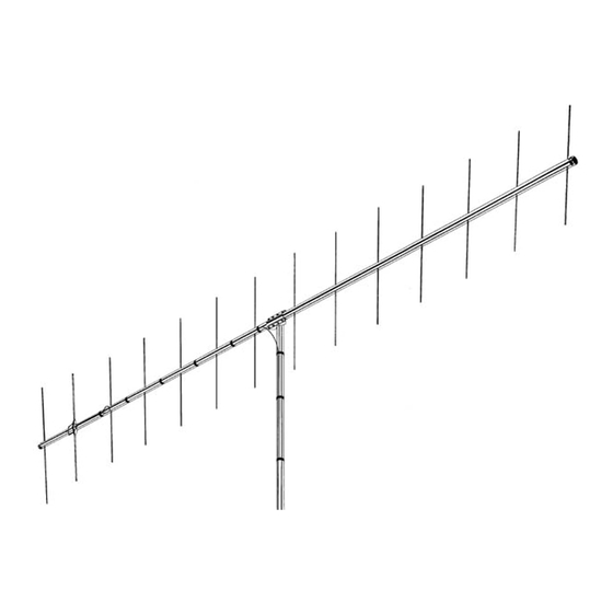
This antenna is a 14-element, closed-spaced, two
meter beam. It features high forward gain associated
with a narrow beam width. It has an excellent front-to-
back ratio and is especially suited for DX contacts
where maximum gain and a narrow beam width is
required.
14 Elements 2-Meter Beam
Figure 1
Overall View
The 214FM antenna now features stainless steel
hardware for all electrical and most mechanical
connections, and a boom-to-mast bracket that will fit
mast diameters up to 2 1/16 inches.
VB-214FM
Advertisement
Table of Contents

Subscribe to Our Youtube Channel
Related Manuals for Hy-Gain VB-214FM


Summary of Contents for Hy-Gain VB-214FM
- Page 1 VB-214FM 14 Elements 2-Meter Beam 308 Industrial Park Road Starkville, MS 39759 USA Ph: (662) 323-9538 FAX: (662) 323- INSTRUCTION MANUAL Figure 1 Overall View GENERAL DESCRIPTION The 214FM antenna now features stainless steel This antenna is a 14-element, closed-spaced, two meter beam.
-
Page 2: Specifications
SPECIFICATIONS Mechanical Boom Length.......………………………………………….........15'6"(4.72 m) Longest Element ....…………………………………....... 39 1/2" (1003 mm) Turning Radius (maximum) ..…………………………………........95" (2.41 m) Wind Survival ..…………………………………….......... 80 mph (129 kmph) Mast Diameter.....…………………………....15/8" to 2 1/16" O.D. (41 mm to 52 mm) Boom Diameter..…………………………………..........1 1/4" O.D. (32 mm) Wind Area ....………………………..... -
Page 3: Installation
INSTALLATION This antenna fits a 2" O.D. mast. A 2" O.D. Select the boom-to-mast backup plate (Item No. 6), the galvanized pipe is recommended for a sturdy mast. boom-to-mast clamp (Item No. 5) and the four (4) 1/4"-20 x 3/4" bolts, 1/4" lockwashers and nuts (Item Nos. - Page 4 Figure 2 Boom-to-Mast Clamp Assembly...
- Page 5 Figure 3 Element Assembly Figure 4 Driven element assembly...
- Page 6 Select the rods from the table below. Mark the center Select the element-to-boom insulator (Item No. 21), point on each rod, then make two more marks 5/8" on two sections of the 7/16" x 17 1/4" Driven element either side of the center mark. Secure the elements to (DE) (Item No.
- Page 7 Figure 6 VSWR and Cutting Chart Figure 7 Vertically Polarized Broadside Stacking Configuration for FM Operation...
- Page 8 STACKING STACKING STACKING STACKING NOTE: When phasing two antennas, the Driven Element halves that are connected directly to the This antenna can be easily stacked for approximately phasing lines should be on the same side of the array 3 dB more gain each time the number of yagi is (either top or bottom).
-
Page 9: Parts List
PARTS LIST Item Part No. Description 170390 Boom, Rear, 1 1/4" x 93" (has extra hole for Beta Match) ... 1 170387 Boom, Front, 1 1/4" x 93........1 175157 Driven Element. 7/16" x 17 114......... 2 170389 Beta Rod, 2 1/2"...........1 385142-1 Clamp, Boom-to-Mast ........ -
Page 10: Limited Warranty
Hy-Gain Warrants to the original owner of this product, if manufactured by Hy-Gain and purchased from an authorized dealer or directly from Hy-Gain to be free from defects in material and workmanship for a period of 12 months for rotator products and 24 months for antenna products from date of purchase provided the following terms of this warranty are satisfied.
Need help?
Do you have a question about the VB-214FM and is the answer not in the manual?
Questions and answers
Wiring diagram?? Why does it look it is a dead short for the connections? The hy-gain instructions aren't good.
The wiring diagram for the Hy-Gain VB-214FM involves connecting the driven element halves to a phasing harness. When stacking two antennas, the driven element halves connected to the phasing lines must be on the same side of the array. The phasing lines are connected to a "T" connector and must be any odd multiple of one-quarter wavelength in 75-ohm coaxial cable.
The appearance of a dead short in the connections is due to the design of the driven element and phasing system. At DC or low frequencies, the connection may appear as a short, but at the operating frequency, the impedance transforms correctly, allowing proper function. This is common in antenna systems using phasing harnesses.
This answer is automatically generated