Table of Contents
Advertisement
Advertisement
Table of Contents

Related Manuals for Aztech WIPC409HD-E


Summary of Contents for Aztech WIPC409HD-E
- Page 1 WIPC409HD-E WIRELESS N PAN/TILT HIGH DEFINITION IP CAMERA V1.0...
- Page 2 User Manual © Copyright 2015 All rights reserved. Ver1.0 No part of this document may be reproduced, republished, or retransmitted in any form or by any means whatsoever, whether electronically or mechanically, including, but not limited to, by way of photocopying, recording, information recording, or through retrieval systems without the express written permission.
-
Page 3: Table Of Contents
About the Product ....................... 5 Function and Features ....................6 Appearance and Interface ..................7 Appearance ......................7 Interfaces of the WIPC409HD-E ................7 LAN Port LED Behaviors .................... 8 Network Connection ....................8 Connection Instructions ..................9 Visiting the IP Camera ..................... 9 Visit IP Camera from LAN .................. - Page 4 Multiple Device Monitor System (MDMS) ............32 Technical Parameters ....................33 Supplementary Section .................... 35 Port Forwarding References ................. 35 Aztech DSL1015EW(S) / DSL1016EN(S2) ............35 Aztech DSL7000GRV(S) ..................36 Aztech DSL7000GR(SME) ................... 37 Linksys E1500 Router.................... 38 DLink DVG-N5402SP .................... 39...
-
Page 5: About The Product
Your IP Camera package should contain the following items. If any of the listed items are missing, please contact your reseller from where you purchased the camera for assistance. The Package includes: WIPC409HD-E LAN Cable Resource CD Utility with ... -
Page 6: Function And Features
Pan-Tilt-Zoom (PTZ) Feature. Compared to other conventional fixed IP cameras which only focus on a single area, the WIPC409HD-E allows you to follow movements and capture various scenes taken from multiple angles through its 355° horizontal pan and120° vertical tilt function which can be flexibly combined with its zoom capabilities. -
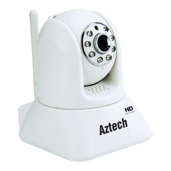
Page 7: Appearance And Interface
2. WPS Button. Press this button for 2 seconds to enable the WPS connectivity of the WIPC409HD-E to a wireless router that has a WPS feature. You may have to browse your router’s instruction manual to know how many seconds it has to be pressed for a successful WPS pairing. -
Page 8: Lan Port Led Behaviors
User Manual LAN Port LED Behaviors LABEL STATE DESCRIPTION Blinking Actively transmitting/receiving data. LED 1 Device is not connected to the network. Steady A LAN Cable is connected to the LAN port. LED 2 There is no LAN cable connected to the LAN Port. Network Connection The IP Camera can be connected to another PC by connecting it to a router, a switch, or a hub, to establish network connectivity as seen above. -
Page 9: Connection Instructions
User Manual Connection Instructions Before visiting the IP Camera, you must first connect it to the Network. Plug it to a power outlet, and check if the light of the LAN port is normal to make sure all of the communication links are functioning properly. The connection method can be seen on the previous page. -
Page 10: Visit Ip Camera From Lan
IP range. As explained earlier, you would not be able to access IP Camera-1. To change the IP address of IP Camera-1: 1. Run the WIPC409HD-E Utility in the CD. 2. Click Find button, and then select the IP Camera on the Equipments list to set the IP Camera’s IP address. -
Page 11: Visit Ip Camera
Setup Instructions 1. Click the Find button and select the WIPC409HD-E camera from the Equipment list seen on the left side of the utility. The required fields on the General tab would automatically be filled up by the selected camera’s device details. -
Page 12: Web User Interface
User Manual After the ActiveX installation, you will be redirected to the Home page of your IP Camera. Simply click View to start viewing. Web User Interface Menu There are 2 kinds of menu (1) is Main Menu, and (2) is the Sub Menu. The Main Menu lies at the top of the interface, including View, Media, Network, Alarm, Advanced and System. -
Page 13: Video Displaying Area
User Manual Video Displaying Area The video displaying area corresponds to the resolution of the IP Camera. The higher the resolution is, the larger the displayed area will be. If the motion detection feature is enabled, the displaying area will show a pane calling the user’s attention if movements were detected on the surveillance area. -
Page 14: Capture
User Manual Capture Allows you to take photos of the current video and store the image at the present path. Record Allows you to record videos with audio and store it using the present path. When recording, there will be an indicated symbol in the status of video display area to show you it is recording. -
Page 15: Notice (For Initial Use)
User Manual Notice (for Initial Use) Please change the following settings for initial use: 1. You may have to change the initial passwords of admin, user, and guest. Their initial passwords are respectively “admin”, “user”, “guest”. 2. You may also have to set the current System Time. -
Page 16: Visit Ip Camera From Wan
User Manual Visit IP Camera from WAN Port Forwarding Ensure PC-1 can visit IP Camera-1. Before the computers in WAN (PC-2, PC-3) can visit IP Camera-1, you must first put the IP Camera -1 into WAN. You can set Port Forwarding on Router-1 to put IP Camera-1 into WAN. 1. -
Page 17: Ddns
User Manual DDNS As explained earlier, Router-1 will get the WAN IP address via ADSL. The WAN IP address constantly changes, which is why the IP address cannot be confirmed. In instances such as this, the Dynamic Domain Name Server (DDNS) would be of great use. -
Page 18: Third Party Domain Name
User Manual Additional Notes : The domain name is made possible through port forwarding. The domain name will change into the IP address and port number of the device when visited through its domain name. If the device can be visited by IP address but can’t be visited by manufacturer’s domain name, please check the DNS info if it is available or not and make sure that the DNS setting is the same with the DNS setting of PC in LAN. -
Page 19: Other Settings
User Manual Other Settings Video Settings Page Video Settings Resolution. Use 1280 X 720 Resolution, Bit Rate is 2048 kbps and Frame Rate is up to 20 fps. The higher the resolution or quality of the picture, the higher bit rate requirement and bandwidth consumption will be. A high bit rate allows the generation of higher image qualities. -
Page 20: Image Settings
User Manual Image Settings Color Adjustment. Allows you to adjust brightness, saturation, and contrast, by either sliding the glide bars of the corresponding setting, or by entering the value that you wish on the corresponding setting. Image Display Adjustment. Allows you to set the monitored area’s vide view into Mirror or Flip. -
Page 21: Wifi Setting
User Manual WIFI Setting The wireless settings page is as shown above. You can click the “Search” button, and it will show you a list of WIFI networks detected. By selecting one SSID, all data fields will be filled up automatically (E.g. SSID, encryption algorithm etc.). All you have to do is to enter the wireless password in the Key and the Re-Type Key field correctly. -
Page 22: Alarm Setting Page
User Manual Alarm Setting Page External Alarm Input If the alarm input pins have been connected with an alarm detector, please tick the “External Alarm”, and then you will have enabled external alarm function. If the external alarm detector is open mode, please tick Open, vice versa. Motion Detection Setting Allows you to monitor movements made on the monitored area. -
Page 23: Alarm Mode Setting
User Manual Alarm Mode Setting Allows you to set how the IP Camera will respond when the alarm is triggered. You can set it to any of the responses enumerated below. Snapshot a live picture of the site on the SD card. ... - Page 24 User Manual 0 - 23 denotes standard format of time (24 hour clock) Left box indicates first 30 minutes / half hour ( 00:01 – 00:30) Right box indicates last 30 minutes / half hour (00:31-01:00) NOTE: The IP Camera will trigger alarm only on the time set.
-
Page 25: Advance Setting
User Manual Advance Setting User Management There are three account levels of authorization: Admin, User, and Guest. The Admin account has the highest authority and can perform all possible changes on the IP Camera’s settings. The User account can only operate the IP camera but it cannot do any changes to its current settings. -
Page 26: Auto Capture Setting
User Manual Auto Capture Setting Allows you to configure the Auto capture settings of your IP Camera such as the SD Card/FTP second intervals, and the enabling/disabling of image saving in SD Card/FTP Server. By ticking the “save picture on the SD card” checkbox, the IP Camera will take a snapshot of the monitored area using the interval declared on the TF/SD Card field (E.g. -
Page 27: E-Mail Setting
User Manual E-mail Setting Allows you to configure the email settings which will be used if the alarm response is set to email alarm. As seen below, the blanks which have been filled with info should be correct. If any info is not filled properly the setting will fail. Before setting these parameters, please refer to the settings of your Outlook Express. -
Page 28: Date And Time Setting
User Manual matches the camera or not before purchasing the SD Card. Date and Time Setting Allows you to identify the NTP Server the IP Camera will synch with. There are three options in setting your IP Camera’s time and date: (1) manually, (2) keeping the same time and date settings of your computer, and (3) is getting it from the NTP server. -
Page 29: System Log Checking
Advanced Application Android and iPhone Mobile Application Set Up 1. Download and Install Aztech IP Cam 2 app at Google Play Store or the Aztech IP Cam app on iTunes/AppStore. You may scan the QR Code found at the Packaging Box to automatically search for the app. -
Page 30: Mobile Phone Browsing
User Manual Password and retype it again on the Confirm password field. 9. To connect your camera via wireless, on the Advanced Setting > Wi-Fi Setting section, tap the Manage Wi-Fi Networks button. 10. Select the Wireless network you want to connect your camera to on the drop down list provided. - Page 31 User Manual 1. In Windows OS, it will remind the users for the installation of Quicktime. After installation, start the Quicktime program. 2. Access the QuickTime Preferences dialog box from Edit Menu. 3. Click Advanced then select “custom..” in the Transport Setup. A Streaming Transport dialog box will popup.
-
Page 32: Multiple Device Monitor System (Mdms)
Multiple Device Monitor System (MDMS) Multi Device Monitor System is a free software offered in conjunction with the WIPC409HD-E which allows several IP Cameras on the LAN and WAN to be browsed at the same time. The software also supports snapshots, video recording and so on. -
Page 33: Technical Parameters
User Manual Technical Parameters Operating Embedded Linux OS System Processor 32Bit RSIC Embedded Processor Network Network RJ45 10/100MB Self-Adaptable Interface Ethernet slot HTTP,UDP,SMTP,FTP,DHCP, Protocol DNS,DDNS,NTP,UPNP Wireless 802.11 b/g/n IP mode Dynamic IP address, Static IP address Video Online Visitor Support 5 visitors at the same time Compression H.264 Format... - Page 34 User Manual Material Environment indoors Power Supply DC5V 2A Operating -10~+50°C Temperature Operating 10%~80% Humidity Dimension Item size: 112x90x116mm (L*W*H) Package size: 200x150x120mm (L*W*H) Weight Item weight:275g Package weight:580g Accessories Power Adapter, Easy Start Guide, Screws , Mounting Bracket Microsoft Win XP,Vista ,Win7,Win8, System System IE6.0、7.0、8.0、9.0 10.0.
-
Page 35: Supplementary Section
Internet Connection is up. After it has been configured successfully, user may now be able to access the IP Camera remotely using another computer. Aztech DSL1015EW(S) / DSL1016EN(S2) Open your browser. Type-in 192.168.1.254 on the address bar and then press Enter. -
Page 36: Aztech Dsl7000Grv(S)
To Remove: Select the Server Name by clicking on Remove check box Click Remove button. Aztech DSL7000GRV(S) 1. Open your browser. 2. Type-in 192.168.1.254 on the address bar and then press Enter. 3. Go to Firewall Configuration, click Port Forwarding 4. -
Page 37: Aztech Dsl7000Gr(Sme)
To Remove: 1. Select the Server Name by clicking on Remove check box. 2. Click Remove button Aztech DSL7000GR(SME) 1. Open your browser. 2. Type-in 192.168.1.254 on the address bar and then press Enter. 3. Go to Firewall Configuration, click Port Forwarding 4. -
Page 38: Linksys E1500 Router
User Manual To Remove: Select the Server Name by clicking on Remove check box Click Remove button Linksys E1500 Router 1. Open your browser. 2. Type-in 192.168.1.1 on the address bar and then press Enter. 3. Type correct Username and Password if required. 4. -
Page 39: Dlink Dvg-N5402Sp
User Manual DLink DVG-N5402SP 1. Open your browser. 2. Type-in 192.168.0.1 on the address bar and then press Enter. 3. Type correct Username and Password if required. 4. Go to Advanced Tab, click Firewall and DMZ at the left column. 5. -
Page 40: 2Wire 2700 Hgv-2
2. Type-in 192.168.1.254 on the address bar and then press Enter to enter the Web User Interface Page of your router. 3. Click Connection Status, this will launch the configuration page. 4. Select Home Network tab then click Edit Firewall Settings. Take note of the WIPC409HD-E Wired Connection Icon. - Page 41 User Manual 5. Click Allow Individual Application (s) and select User-Defined from the drop down box then click Add a new user-defined application. 6. On the Application Name box input the IP Camera’s Name, select TCP on the Protocol option. Input 8081 under the Port (or Range) field then click ADD DEFINITION.
- Page 42 User Manual 7. WIPC409HD-E IP Camera Configuration will be added on the Definition List Table. Click Back to return to the Firewall Settings. 8. Click Home Network again then click Edit Firewall Settings on the WIPC409HD-E Wired Connection.
- Page 43 User Manual 9. Under the All Application box select WIPC409HD-E then click ADD for the application to be added on the Hosted Application list. Click DONE for the settings to take effect.
- Page 44 User Manual Copyright © 2015 Aztech Technologies Pte Ltd (CRN:199800635M). All rights reserved.
Need help?
Do you have a question about the WIPC409HD-E and is the answer not in the manual?
Questions and answers