
Related Manuals for Comelit HFX-700M KIT


Summary of Contents for Comelit HFX-700M KIT
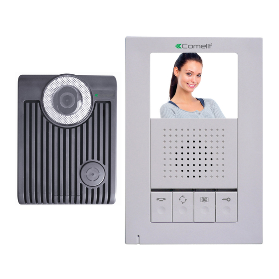
- Page 1 HANDS-FREE EXPANDABLE VIDEO INTERCOM SYSTEM HFX-700M KIT OWNER S MANUAL INSTALLATION AND OPERATION...
-
Page 2: Table Of Contents
TABLE OF CONTENTS Section 1: User Article 1.Introduction 2.HFX-700M KIT 2.1.HFX-700M KIT Parts Identification 2.1.1.HFX-700M Main monitor identification 2.1.2.HFX-700M or EX-700D door camera identification 2.2.HFX-700M KIT Operation 2.2.1.Visitor calls from door camera 2.2.2.Audio and video monitoring 2.2.3. Push to talk mode(similar to walky-talky) 3.Expansion video monitor (EX-700H) - Page 3 Section 2: Installation Article 1. System layout Read before installation 3. HFX-700M installation 3.1.Examine package contents 3.2.Install main monitor 3.3.Install door camera 3.4.HFX-700M wiring and setting 3.5.Jumper function on main monitor 3.5.1.JP1, video display option during door release operation 3.5.2.JP2, door status report options external doorbell trigger options 3.5.3.JP3,...
-
Page 4: Section 1: User Article
Section 1: User Article 1.Introduction Thank you for purchasing the Hands-Free expandable Video Intercom System HFX-700M. This intercom system uses 2-wire installation and allows you to identify and communicate with callers at the door, from the security and convenience of any room in your home or office. Visitors activate the system by pressing a call button on the outdoor camera, which sounds a doorbell chime as well as turning on the inside video monitor. -
Page 5: Hfx-700M Kit
2. HFX-700M KIT 2.1.HFX-700M KIT Parts Identification [M ain monitor] 178mm (7.0 ) 36mm 9 10 11 (1.42 ) 118mm (4.65 ) 2.1.1 HFX-700M Main monitor identification 3.5" Color TFT Screen Speaker In use LED Monitor LED Intercom LED Communication LED... -
Page 6: Hfx-700M Or Ex-700D Door Camera Identification
[Door Station] 130mm (5.12 ) " 36mm 98mm (1.42 ) " (3.86 ) " 2.1.2. HFX-700M or EX-700D Door Camera identification White LED Illumination 1/3" Color CCD Microphone Speaker Call button Screw cover CCD vertical view angle adjustment dial (-6 degrees, 0 degrees, 8 degrees, 16 degrees) Wire to door strike Wire to main Monitor JP 2 (automatic LED light supplement option) -
Page 7: Hfx-700M Kit Operation
2.2. HFX-700M KIT Operation Operating the video intercom system consists of responding to visitor calls from door camera, releasing a door strike from indoor monitor; audio and video monitoring from any indoor monitor; voice broadcast from one monitor to all others; engage intercom function after voice broadcast. -
Page 8: Expansion Video Monitor (Ex-700H)
3. Expansion Video Monitor (EX-700H) 3.1. EX-700H Identification [E X-700H] 178mm (7.0 ) 36mm 9 10 11 (1.42 ) 118mm (4.65 ) 3.5" Color TFT Screen Speaker In use LED Monitor LED Intercom LED Communication LED Microphone Cut-off button( ) Intercom button( ) 10. -
Page 9: Ex-700H Operation
3.2. EX-700H Operation Operates the same as the main monitor unit (Refer to page 4). 3.2.1.Broadcast and intercom function A. When system consists of main monitor and expansion monitor and an outdoor doorbell/camera unit, the system can provide intercom function. B. -
Page 10: Expansion Audio Monitor (Ex-700A)
4. Expansion Audio Monitor (EX-700A) 4.1. EX-700A Identification [E X-700A] 178mm (7.0 ) 36mm (1.42 ) 118mm (4.65 ) Speaker In use LED Monitor LED Intercom LED Communication LED Microphone Cut-off button( ) Intercom button( ) Monitoring button( ) 10. Door release button( ) 11. -
Page 11: Ex-700A Operation
4.2. EX-700A Operation A. Operates the same as the main monitor unit (Refer to page 13). B. EX-700A only audio function, not video function. 4.2.1.Broadcast and intercom function A. When system consists of main monitor and expansion audio monitor and an outdoor doorbell/camera unit, the system can provide intercom function. -
Page 12: Optional Video Input Converter (Ex-Vin)
Optional video input converter (EX-VIN) 5.1. EX-VIN Identification Power LED The 2-wire terminals for connecting ot the main monitor BNC connector for external camera video input 5.2. EX-VIN Operation AA. EX-VIN converts video signal on the 2-wire transmission format of the system. -
Page 13: Section 2: Installation Article
100m AWG#18 100m Signal wires (328 feet) (328 feet) parallel wires NOTE : CAT-5 is not recommended for this type of installation. B Max B Max B Max A Max A Max EX-700D HFX-700M KIT EX-700H or EX-700A... - Page 14 System layout 2: NOTE 1: The wiring HUB can amplify and distribute the 2-wire signal among the main monitor and sub-monitors. NOTE 2: the system is capable of expanding up to a total of 5 monitors with 1 EX-HUB or 8 total monitors with 2 EX-HUBs connected in one system. Maximum wiring distance (using dry contact lock control at doorbell camera) Wire type...
- Page 15 A Max A Max HFX-700M EX-700D EX-700H or EX-700A B Max C Max EX-HUB OUT1 OUT2 OUT3 POWER OUT4 POWER LED EX-700H or EX-700A NOT E 1:OUT4 can also be used to connect to a expansion monitor. NOT E 2:wiring distance<300ft.
-
Page 16: Read Before Installation
2. Read before installation Main monitor Door camera Proper height: View Angle: 70cm 100cm (27.6 ) " (39.3 ) " 165cm 170cm (64.9 ) " (66.9 ) " 50cm(19.7 ) " 50cm(19.7 ) " The proper height of monitor or door camera is 160~170cm(63"~67") from the ground. -
Page 17: Hfx-700M Installation
3. HFX-700M installation 3.1.Examine package contents NOTE: Examine the following contents of the package. HANDS-FREE EXPANDABLE PT 1 VIDEO INTERCOM SYSTEM PT 2 OUT+ OUT- < +> PO W E R < -> Wall mount bracket OWNER S MANUAL INSTALLATION AND OPERATION Main monitor Door camera Manual... -
Page 18: Install Door Camera
3.3. Install door camera A. Open the hidden latch, and unscrew to remove door camera unit from bracket. B. Fasten wall mount bracket to the surface where the unit will be installed. C. Fasten wires on terminals and select jumpers for desired function (Refer to 3.6). -
Page 19: Jumper Function On Main Monitor
3.5. Jumper function on main monitor 3.5.1. JP1, video display option during door release operation A.Enable video display (JP1 left ) (default) if door release is dry contact output. B.Disable video display (JP1 right ) if door release is 12VDC/300mA direct current output 3.5.2. -
Page 20: Jumper Function On Door Camera
3.6. Jumper function on door camera 3.6.1. J P1, door control options and CCD on/off during the output Each Door Camera on the system is able to operate and release one electric lock. On a full system with 2 door cameras, the user is able to release up to two electric locks. -
Page 21: Expansion Video Monitor(Ex-700H) Installation
4. Expansion v ideo monitor(EX-700H) Installation 4.1. Examine package contents NOTE: Examine the following contents of the package. White wall mount screws OUT+ OUT- <+ > P O WE R <-> Expansion monitor Wall mount bracket Adaptor Flat head screws 4.2. -
Page 22: Install Expansion Video Monitor
4.3. EX-700H wiring and setting A. Wire the system from terminal to terminal accordingly. Expansion monitor Main monitor wiring terminal Wiring terminal Magnetic switch OUT+ OUT- OUT+ OUT- To next expansion monitor <+> <+> POWER Black <-> POWER <-> Black Terminals for expansion monitor (w/polarity) Connect to a N.C. -
Page 23: Expansion Audio Monitor(Ex-700A) Installation
5. Expansion audio monitor(EX-700A) Installation 5.1. Examine package contents NOTE: Examine the following contents of the package. White wall mount screws PT 1 PT 2 OUT+ OUT- < +> PO W E R < -> Expansion Wall mount bracket Adaptor Flat head screws non-video monitor 5.2. -
Page 24: Ex-700A Wiring And Setting
5.3. EX-700A wiring and setting A. Wire the system from terminal to terminal accordingly. Expansion monitor Main monitor wiring terminal Wiring terminal Magnetic switch OUT+ OUT- OUT+ OUT- To next expansion monitor <+> <+> POWER Black <-> POWER <-> Black Terminals for expansion monitor (w/polarity) Connect to a N.C. -
Page 25: Expansion Door Camera (Ex-700D) Installation
6. Expansion door camera (EX-700D) Installation 6.1. Examine package contents NOTE: Examine the following contents of the package. security White wall Flat head screws screw wrench Door Camera mount screws 6.2. Install expansion door camera A. Open the hidden latch, and unscrew to remove door camera unit from bracket. -
Page 26: Metal Door Camera Housing (Ex-700V) Installation
Metal door camera housing (EX-700V) installation 7.1. Examine package contents A. Examine the following contents of the package. B. EX-700V is an optional housing assembly kit to enclose EX-700D to become flush mount metal doorbell camera. C. C. Depending on different wall materials, please be careful to cut the hole according to the measurements below to fit the flush mount bracket for the EX-700V. -
Page 27: Assembly Procedure
7.2. Assembly Procedure STEP 1-1 : A. If on wooden wall, cut open space is 100x150x41mm. B. Embed box may not necessary. Go to Step 2. STEP 1-2 : A. If on cement or brick wall, cut open a hole size of 114x165x49mm. B. -
Page 28: Optional Video Input Converter (Ex-Vin) Installation
8. Optional video input converter (EX-VIN) Installation 8.1. Install video input converter A. Package contains no accessories. B. Wire EX-VIN to the video distribution box of the camera C. Plug in BNC, no setting is necessary 8.2. EX-VIN wiring and setting OUT+ OUT- EX-VIN wiring terminal... -
Page 29: Technical Specifications
9. Technical Specifications 9.1. HFX-700M(main monitor) specification Display: 3.5 digital TFT-LCD " Resolution: 320 x 240 pixels Auto Timer (visitor call): 30 seconds time out; 90 seconds for conversation Auto Timer (intercom): 20 seconds time out; 90 seconds for conversation Operating Temperature: 14 F ~ 140 F, indoor Dimensions (w/ bracket):... - Page 30 9.4. EX-700H specification (optional video monitor) Display: 3.5 digital TFT-LCD " Resolution: 320 x 240 pixels Auto Timer (visitor call): 30 seconds time out; 90 seconds for conversation Auto Timer (intercom): 20 seconds time out; 90 seconds for conversation Operating Temperature: 14 F ~ 140 F, indoor Dimensions (w/ bracket): 4.65 (L) x 7.0 (W) x 1.42 (D)
-
Page 31: Trouble Shooting
10. Trouble Shooting Note: Before requesting service, check the troubleshooting quide to solve the problem. Problem Solution Make sure AC plug is firmly inserted into the AC outlet. Make sure the power terminal is No power firmly connected into the monitor unit. Check (no picture on monitor) to ensure polarity is correct. -
Page 32: Section 3: Appendix
Section 3: Appendix APPENDIX 1: WARNING WARNING: TO REDUCE THE RISK OF FIRE OR ELECTRIC SHOCK, DO NOT EXPOSE THE MONITOR OR POWER ADAPTER TO WATER OR MOISTURE. CAUTION: DO NOT OPEN. RISK OF ELECTRICAL SHOCK. CAUTION! TO REDUCE RISK OF ELECTRICAL SHOCK, DO NOT REMOVE COVER OR BACK, NO USER SERVICEABLE PARTS INSIDE, REFER SERVICING TO QUALIFIED SERVICE PERSONNEL. - Page 33 APPENDIX 2: IMPORTANT SAFETY INSTRUCTIONS WARING: TO RE DUCE TH E RISK OF FIRE OR E LECTRIC SHOCK , DO NOT E XPOSE THE MONITOR OR POW ER ADAP TER TO WATE R OR MOIST URE . Read Instructions -All the safety and operating instructions should be read before operating this equipment.
- Page 34 APPENDIX 3: FCC CLASS B NOTICE NOTE: This equipment has been Certified and found to comply with the limits regulated by FCC,and CE. Therefore, it is designed to provide reasonable protection against interference and will not cause interference with other appliance usage.
- Page 35 APPENDIX 4: SERVICE AND WARRANTY To receive after sales service, please provide the follow ing information when contact. a. Name of the product b. Model and serial number of the product c. The store s name where you purchased d. Date purchased e.
- Page 36 http:// w w w .comelitusa.com Info@comelitusa.com...
Need help?
Do you have a question about the HFX-700M KIT and is the answer not in the manual?
Questions and answers
Our door station camera on our HFX-700 system is very cloudy. Can we replace the door station without upgrading the other components?
Yes, the door station camera (EX-700D) on the Comelit HFX-700M KIT can be replaced without upgrading other components, as long as the replacement is compatible with the system. The system supports up to 2 door cameras and allows expansion without requiring upgrades to the main monitor or other parts.
This answer is automatically generated
I need to use an ! in my wifi password and can't find it on the device