
Related Manuals for Comelit HFX-7000M


Summary of Contents for Comelit HFX-7000M
- Page 1 QUICK REFERENCE GUIDE PUSH HERE Quick reference Guide for Single-User Kit HFX-7000M also available in French and Spanish...
-
Page 2: Contents Of The Package
×1 ×1 ×4 ×4 dry wall monitor backplate anchors screws 1209/4 - BUS Power supply Technical manual QUICK REFERENCE GUIDE ×1 ×2 Quick reference Guide for Single-User Kit HFX-7000M also available in Passion.Technology. Design. French and Spanish power supply screws... -
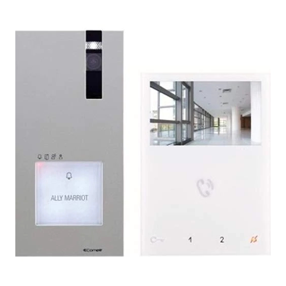
Page 3: Parts Identification
2. Parts identification 3.79 in 1.06 in 2.1 EX-DSME EXTERNAL UNIT PUSH HERE 1. Die-cast aluminium cover 9. PR programming input/output switch 2. Camera lighting LED 10. CNF programming confirmation switch 3. Wide-angle colour camera 11. Loudspeaker volume control 4. Loudspeaker 12. - Page 4 2.2 EX-7000H MONITOR 4.52 in 0.83 in 1. Loudspeaker volume control Capacitive-touch key description: 2. Brightness control „ Press the desired key once to activate the function associated with it. 3. 4.3" Color LCD Screen Wait for approximately 1 sec. before pressing the same 4.
- Page 5 2.3 1209/4 BUS POWER SUPPLY 4.17 in 3.52 in Dopo un cortocircuito,per ripristinare l'apparecchio, interrompere l'alimentazione per circa 1 minuto. To reset the operation after a short circuit,cut o mains voltage for about 1 minute. Apres un court circuit, pour remettre en fonction l'appareil, Art.1209/4 interrompre l'alimentation pendant environs une minute.
- Page 6 (170 m) 1,181 feet 590 feet 590 feet non-braided cable AWG18 (360 m) (180 m) (180 m) 3.1.1 Single-User Kit art. HFX-7000M 3.1.2 Maximum expansion monitors in daisy chain connection EX-7000H EX-7000H EX-7000H expansion monitor expansion monitor EX-7000H EX-7000H 1209/4...
- Page 7 1405 Video door expander. EX-DSQE EX-DSME 1405 3.1.3 Full System Expansion Diagram EX-7000H EX-7000H EX-7000H EX-7000H expansion monitor expansion monitor expansion monitor 1209/4 EX-DSQE EX-DSQE EX-DSQE expansion external unit expansion external unit expansion external unit 1405 1405 1405 EX-DSME EX-DSME EX-DSME EX-DSME HFX-7000M...
-
Page 8: Leave Default Setting
Basic single-user kit STANDARD INSTALLATION EX-7000H LEAVE DEFAULT SETTING 34 Vdc 1209/4 LP LP L1 L1 L2 L2 L3 L3 L4 L4 110-240V EX-DSME Local lock release button Wiring diagram: MNVK/039QCU... - Page 9 LEAVE DEFAULT SETTING EX-7000H EX-7000H REMOVE CV5 REMOVE CV5 LEAVE DEFAULT SETTING LEAVE DEFAULT SETTING 1209/4 LP LP L1 L1 L2 L2 L3 L3 L4 L4 110-240V EX-DSME REMOVE WHEN LINE IS USED HFX-7000M Video Closing Jumper Wiring diagram: MNVK/Q19U...
- Page 10 Expanded single-user kit MAXIMUM EXPANSION Wiring diagram: MNVK/012BQCU...
- Page 11 3.2 ASSEMBLY MINI HANDSFREE ART. EX-7000H INTERNAL UNIT optional fixing TO OPEN REMOVING THE TERMINAL INSERTING THE TERMINAL...
- Page 12 3.3 INSTALLATION OF EXTERNAL UNIT ART. EX-DSME COUNTERCLOCKWISE The camera must not be installed in front of light sources, or in places where the filmed subject is against the light. In dim environments, we recommend additional lighting is provided. 19.68 in CAUTION! 72°...
- Page 13 You can download the free software (art. 1235A) from the website pro.comelitgroup.com to print the entrance panel name tags, using the adhesive pre-cut sheets available in our catalogue (art. 1217A) CLACK! CLACK! CORRECTLY! Before fixing the screw, make sure that you do not need to program the external unit (see the “4.6 Configuration EX-DSME” section on the complete manual pro.comelitgroup.com) and make sure that the metal front panel does not rub against other metal parts, with consequent risk of damage to its insulating coating.
-
Page 14: Table Of Contents
3.4 EXPANDED UP TO 4 FAMILIES EX-7000H Address LEAVE DEFAULT SETTING EX-7000H Address to set EX-7000H Address to set EX-7000H Address to set 1209/4 LP LP L1 L1 L2 L2 L3 L3 L4 L4 110-240V REMOVE WHEN LINE IS USED EX-DSME »... -
Page 15: Address
3.4.1 Call address programming for 2/4 users √ Take note of the DIP-switch settings. DIP-Switch ON Function Cod. button 1 enabled with call address 1 (default) buttons 1-2 enabled with example: call addresses 1-2 buttons 1-2-3-4 enabled with call addresses 1-2-3-4 Restore default 2,3,4,5,6,7,8... -
Page 16: System Function
5. System function Answer call / Paging call Lock-release key Key 1 Programmable button Key 2 Self-ignition function (programmable) Privacy mode 5.1 PERFORMING CALLS 5.1.1 How to call from the external unit 5.1.2 How to answer a call from an internal unit »... - Page 17 5.3 SELF-IGNITION FUNCTION √ Self-ignition is possible only when the system is in standby „ Press again to cycle through several cameras „ Press the self-ignition button ( by default) to display on the If a call is underway with an external unit it is NOT possible monitor the video from the external unit.
-
Page 18: Technical Specification
6. Technical specification 6.1 EX-7000H MAIN MONTOR Display 4.3’’ Color LCD Screen Resolution 480x272 pixel Auto Timer (intercom) 300 sec Operating Temperature Class B1 normal range indoor 41° F /104° F (5°C / 40°C) Dimensions (with bracket) W×H×D 4.52×6.29×0.83 in (115×160×21.5 mm) Power consumption 10 W MAX 6.2 EX-DSME EXTERNAL UNIT Image Sensor ¼”... - Page 19 7. Appendix 7.1 WARNING WARNING: TO REDUCE THE RISK OF FIRE OR ELECTRIC SHOCK, DO NOT EXPOSE THE MONITOR OR POWER ADAPTER TO WATER OR MOISTURE. CAUTION: DO NOT OPEN. RISK OF ELECTRICAL SHOCK. CAUTION! TO REDUCE RISK OF ELECTRICAL SHOCK, DO NOT REMOVE COVER OR BACK, NO USER SERVICEABLE PARTS INSIDE, REFER SERVICING TO QUALIFIED SERVICE PERSONNEL.
- Page 20 • Consult the dealer or an experienced radio or television technician 7.4 GENERAL PRODUCT WARRANTY: For all Comelit Branded Products 2 year manufacturer’s warranty from dealer date of Purchase. Proof of purchase by the dealer in the form of an invoice is necessary for all returns.
Need help?
Do you have a question about the HFX-7000M and is the answer not in the manual?
Questions and answers