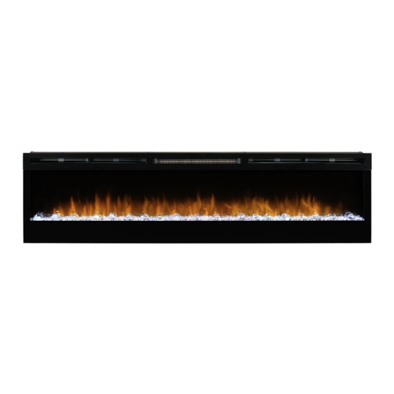
Dimplex BLF74 Servise Manual
Hide thumbs
Also See for BLF74:
- Owner's manual (21 pages) ,
- User manual (3 pages) ,
- Owner's manual (63 pages)
Table of Contents
Advertisement
IMPORTANT SAFETY INFORMATION: Always read this manual first before attempting to service this fireplace. For your
safety, always comply with all warnings and safety instructions contained in this manual to prevent personal injury or prop-
erty damage.
Dimplex North America Limited
1367 Industrial Road Cambridge ON Canada N1R 7G8
1-888-346-7539 www.dimplex.com
In keeping with our policy of continuous product development, we reserve the right to make changes without notice.
© 2013 Dimplex North America Limited
Service Manual
Model
BLF74
UL Part Number
6908740100
REV
PCN
DATE
00
-
26-NOV-13
7400740000R00
Advertisement
Table of Contents

Related Manuals for Dimplex BLF74


Summary of Contents for Dimplex BLF74
- Page 1 Dimplex North America Limited 26-NOV-13 1367 Industrial Road Cambridge ON Canada N1R 7G8 1-888-346-7539 www.dimplex.com In keeping with our policy of continuous product development, we reserve the right to make changes without notice. © 2013 Dimplex North America Limited 7400740000R00...
-
Page 2: Table Of Contents
NOTE: Procedures and techniques that are considered important enough to emphasize. CAUTION: Procedures and techniques which, if not carefully followed, will result in damage to the equipment. WARNING: Procedures and techniques which, if not carefully followed, will expose the user to the risk of fire, serious injury, or death. www.dimplex.com... -
Page 3: Operation
Figure 1 CAUTION: If you need to continuously reset the heater, disconnect power and call Dimplex customer service at 1-888-DIMPLEX (1-888-346-7539). Remote Control The fireplace is supplied with a radio frequency remote control. -
Page 4: Maintenance
Fireplace Surface Cleaning Use only a damp cloth to clean painted surfaces of the fireplace. Do not use abrasive cleaners. Servicing Except for installation and cleaning described in this manu- al, an authorized service representative should perform any other servicing. www.dimplex.com... -
Page 5: Exploded Parts Diagram
EXPLODED PARTS DIAGRAM REPLACEMENT PARTS LIST 1. Element ......2200510700RP 12. LED Driver Board ....3000810200RP 2. -
Page 6: Wiring Diagram
Different Heat Control Options 3. For installation with a 2. For No Heat installations 1. Regular installation Heat Disconnect Switch leave L2 unconnected with attach Neutral and L2 to a wire connector on the end the panel Wall On/Off Switch www.dimplex.com... -
Page 7: Preparation For Service
PREPARATION FOR SERVICE Figure 3 Mounts (4) NOTE: All components are replaceable from the front of the fireplace while the unit is mounted on the wall, with Hooks (4) the exception of replacement of the power cord. NOTE: If the power cord needs replacing or if the unit needs to be removed from the wall for any other reason please begin service by following the “PREPARATION FOR SERVICE”... -
Page 8: Flush Mount - Complete In-Wall
There are 2 screws per side, going from the side Figure 7 panels out into the side of the wall stud that frames the Figure 6 Wall Surface Mounting Hole www.dimplex.com... -
Page 9: Remote Switchboard Replacement
REMOTE SWITCHBOARD Figure 8 REPLACEMENT Controls Assembly WARNING: Disconnect power before attempting any maintenance or cleaning to reduce the risk of electric shock or damage to persons. CAUTION: If unit was operating prior to servicing allow at least 10 minutes for lights and heating elements to cool off to avoid accidental burning of skin. -
Page 10: Led Driver Board Replacement
5. Remove the LED driver board off the plastic mounts by pinching the plastic mounting tabs with needle nose pliers. Pull the old board off. 6. Line up the holes on the driver board and gently press the new board onto the mounts. Make sure the board www.dimplex.com... -
Page 11: Flicker Motor/ Flicker Rod Replacement
by loosening the 3 small Philips screws holding each Figure 10 wire in place then gently pulling the wires out of the terminal block - noting their original locations. 7. Remove the 2 screws holding the flicker motor to the mounting bracket. -
Page 12: Led Light Strips Replacement
7. Cut the wires on either side of the housing bracket that attache to the board. 8. Remove the 2 screws that attach the LED strip to the housing bracket. Blower Heating 9. Replace the LED strip with the new one, by feeding the Assembly Cover www.dimplex.com... -
Page 13: Element Replacement
they can both be easily reached. Holding both suction remove the 4 screws that hold the element cover to the cup handles, tilt the glass forward and lift out. Carefully housing panel. place the glass aside in a safe location. 6. - Page 14 NOTE: Using a flat head screwdriver gently pry between the end of the connectors and the blower/fan to release the wires. 11. Properly orient the new blower/fan assembly and con- nect all of the wiring connections. 12. Reassemble in the reverse order as above. www.dimplex.com...
-
Page 15: Troubleshooting Guide
TROUBLESHOOTING GUIDE PROBLEM CAUSE SOLUTION General Circuit breaker trips or fuse Short in unit wiring. Trace wiring in unit. blows when unit is turned on Improper circuit current rating Additional appliances may exceed the current rating of the circuit breaker or fuse. Plug unit into another outlet or install unit on a dedicated 15 amp circuit. - Page 16 Grinding or excessive noise with Flicker rod hitting or rubbing against Ensure rod is straight and mounted properly in the the heater off internal components bracket, spinning freely away from other components. Replace if necessary. Defective Flicker motor Replace Flicker motor www.dimplex.com...
Need help?
Do you have a question about the BLF74 and is the answer not in the manual?
Questions and answers