Advertisement
Quick Links
D-304674
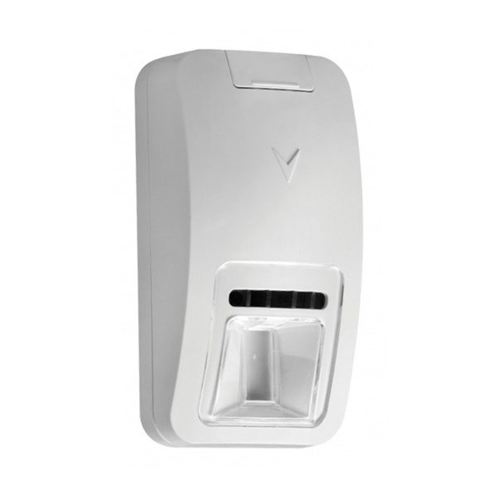
PG9974(P)/PG8974(P)/PG4974(P)
Wireless PowerG High-security Mirror Detector
with Anti-masking Installation Instructions
Features
The PGx974(P) (pet-immune) are 2-way, microprocessor-con-
trolled, wireless digital mirror PIR detectors which include the
following features:
• Built-in link quality indicators reduce installation time by
eliminating the need for the installer to physically approach
the control panel.
• Adaptive Active Infra-Red Anti-Masking technology
providing the most advanced reliable protection against
intentional masking attempts (patent pending).
• Includes a fully supervised PowerG transceiver.
• Incorporates patent pending black mirrors for extremely
high white light immunity.
• Advanced elliptical / parabolic mirror technology
(patented).
• V-slot® optic technology (patented) for improved
robustness, anti-vandalism and for very high reliability.
• Creep zone protection.
• PGx974P can distinguish between human beings and pets
weighing up to 18 kg (40 lb).
• The advanced True Motion Recognition™ algorithm
(patented) distinguishes between the true motion of an
intruder and any other disturbances which may cause false
alarms.
• No vertical adjustment is needed.
• Motion event counter determines whether 1 or 2
consecutive motion events will trigger an alarm.
• Automatic termination of walk-test after 15 minutes.
• Microprocessor-controlled temperature compensation.
• Sealed chamber protects the optical system.
• Front and back tamper protection.
• Self-test.
Device Setup
Note: To ensure the continued operation of all wireless devices
after performing a system default, a global upload of all wire-
less programming via DLS is recommended before defaulting
the system. After completing the system default, download the
wireless programming.
A
D
E
F
B
C
Legend
A. Screw cover
B. LED
C. PIR optical window
D. Enroll button (use a screwdriver to press the recessed but-
ton)
E. Battery
F.
Tamper switch
G. Break-away base segment (shaded)
H. Mounting height
I.
Coverage range
J.
Horizontal view
K. Vertical view
X. Lower surface (with downward tilt)
Y. Upper surface (without downward tilt)
Installing the Battery
1
2
3
4
Caution! Risk of explosion if battery is replaced by an incor-
rect type. Dispose of used batteries according to the manufac-
turer's instructions and according to local rules and regulations.
Batteries are to be replaced by service persons only.
1. On the indicated location, lift the screw cover upward using
your thumb.
2. Release the screw and open the cover in the direction shown
by the arrow.
3. Insert a screwdriver into the slot and then push inward to sep-
arate the base from the cover.
4. Insert battery while observing polarity.
Note: When manually programming wireless devices, if a
device has been powered up for more than 48 hours it cannot be
enrolled into the system until the device has been tampered and
restored. When programming the panel using the Quick Enroll
procedure follow the steps detailed in Enroll the Device into the
System.
Note: After restoring a low battery trouble the system may take
up to 5 minutes to clear the trouble.
Enroll the Device into the System
To quick enroll:
1. On a keypad press [*] [8] [Installer Code] [804] [000].
2. Press and hold the device enroll button until the LED lights
steady and then release the enroll button while the LED is
still lit. A confirmation message then appears on the keypad.
3. Press [*] key to confirm ID.
4. Enter [3 digit zone #].
5. Enter [3 digit zone type].
6. Enter [1 digit partition #] for all desired partitions and press
[#]. If using an LCD keypad you can scroll to the desired par-
titions and press [*] to toggle the partition.
7. On an LCD keypad enter the label by using word library.
To pre-enroll:
1. Remotely configure the unique ID number into the system.
For more information see the HSM2HOST manual.
2. When on-site, press the device enroll button.
Note: If the wireless device has been powered for more than 48
hours without being enrolled, tamper and restore the device to
enroll it.
Perform a Placement Test
Before permanently mounting any wireless device, temporarily
mount the device and perform a Placement test.
1. Tamper the device by removing the cover.
2. Restore the tamper. The device now enters Placement test
mode for 15 minutes.
3. Trip the device and the red LED blinks once to identify that a
signal is being sent to the receiver and then blinks three times
to identify the signal strength. To perform a walk test, walk
across the far end of coverage pattern in both directions. The
following table indicates the received signal strength indica-
tion.
LED Response
Signal Strength
Green LED blinks
STRONG
Orange LED blinks
GOOD
Red LED blinks
POOR
No blinks
No communication
IMPORTANT! Only GOOD or STRONG signal strengths are
acceptable. If you receive a POOR signal from the device, re-
locate it and re-test until a GOOD or STRONG signal is
received.
Note: For UL/ULC installations, only STRONG signal levels
are acceptable. After installation verify the product functional-
ity in conjunction with the compatible receivers HSM2HOST9,
HS2LCDRF(P)9, HS2ICNRF(P)9 and PG9920.
Note: For detailed Placement instructions refer to the control
panel Reference Guide.
Note: Perform a walk test of the coverage area at least once a
year to ensure that the detector is working correctly.
Mounting
Note: Mount the detector so that its orientation is perpendicular
to the expected intrusion path. For the desired detector's range
and height, use mounting holes x or y, as specified in the table
below.
Note: To be installed by service persons in non-hazardous loca-
tions only.
Use the following as a guide for locating a suitable mounting
location:
• Keep away from heat sources.
• Do not expose to air drafts.
• Do not install outdoors.
• Avoid direct sunshine.
• Keep wiring away from power cables.
• Do not install behind partitions.
• Mount on solid stable surface.
H
Y
Y
ft
m
G
10
3.0
X
X
X
X
9
2.7
G
X
X
X
Y
8
2.4
X
X
Y
Y
I
7
2.1
x
b
Y
Y
Y
x
6
1.8
15
30
45
60 ft
6
9
12
15 m
Caution! The back tamper switch will not protect the unit
unless the break-away base segment is secured to the wall with
at least one screw.
Configuration
To enter the wireless configuration section enter [804][000].
Device Toggles
[001][01]
Alarm LED - Default [Y]
Enables the devices LED to activate when an alarm
event occurs.
[001][04]
Supervision - Default [Y]
Enables supervision of the device.
Selections
[003]
Hightraffic Shutdown - Default [01]
Activating this feature helps conserve battery power
when the system is disarmed by configuring a reporting
timer. When motion is detected, the device transmits an
alarm to the receiver and will not report any further
events until the timer expires. Any motion detected
during the configured period will be reported once the
timer expires. No Delay causes the device to report an
alarm each time the detector is tripped.
[01] Detector Dis-
[02] No Delay
[03] 5 second
abled (while dis-
delay
armed)
[04] 15 second
[05] 30 second
[06] 1m delay
delay
delay
[07] 5m delay
[08] 10m delay
[09] 20m delay
[10] 60m delay
Event counter - Default [002]
[016]
Alarm activates after a configured number of events
have been detected.
Key in activities
001-255
Event Indications
LED Indications
Event
Red LED blinks
Stabilization (warm-up 120
sec)
Red LED ON 0.2 sec.
Tamper open / close
Red on 2 sec.
Intruder alarm
Yellow LED on
AM detection – Diagnostic
mode
Yellow LED blinks slowly
AM detection – Normal
(0.2 sec. ON, 30 sec. OFF)
mode
LED Indications
Event
Yellow and red LED blink
Self-test failure – Diagnostic
simultaneously (0.2 sec. ON
mode
[both], 0.2 sec. OFF)
Yellow and red LED blink
Self-test failure – Normal
simultaneously slowly (0.2
mode
sec. ON [both], 30 sec. OFF)
Specifications
GENERAL
Detector Type: Dual element low-noise pyroelectric sensor
Lens Data
No. of Beam Elements:18x3=54 far parabolic mirror seg-
ments
J
10m
32. 8ft
5m
16. 4ft
0
5m
16. 4ft
10m
32. 8ft
0
5
10
15 m
16.4
32. 8
49.2 ft
K
2.1 m
(6.9 ft)
5
10
15 m
16.4
32.8
49.2 ft
Max. Coverage: 15 m (49 ft) / 90°25 m (82 ft) x 2.5 m
Pet Immunity (only): Up to 38 kg (85 lb)
ELECTRICAL
Internal Battery: 3V Lithium battery, type CR-123A (option-
ally can be used type CR-17450)
Note: For UL installations use Gold Peak (GP) only. Use only
the above battery type.
Nominal Battery Capacity: 1450 mA/h ( 2400mA/h for
optional CR17450)
Low Battery Threshold: 2.45 V
Battery Life (for typical use): 7 years (not tested by UL/ULC)
FUNCTIONAL
True Motion Event Verification: 2 remote selections - 1
(OFF) or 2 (ON) motion events
Alarm Period: 2 seconds
WIRELESS
Frequency Band (MHz): CE Listed PG4974: 433MHz; CE/
EN listed PG8974: 868MHz; FCC/IC/UL/ULC listed PG9974:
912-919MHz
Communication Protocol: PowerG
Supervision: Signaling at 4-min. intervals
Tamper Alert: Reported when a tamper event occurs and in
any subsequent message, until the tamper switch is restored
MOUNTING
Height: 1.8 – 3.0 m (6 - 10 ft).
Installation Options: Surface or corner
ACCESSORIES
PGBRACKET-1: Surface mounted swivel bracket, adjustable
30° down and 45° left/45° right.
PGBRACKET-2: PGBRACKET-1 with a corner adapter
PGBRACKET-3: PGBRACKET-1 with a ceiling adapter
Note: UL did not evaluate the product with the use of brackets.
ENVIRONMENTAL
RFI Protection: >20 V/m up to 2000 MHz, excluding inband
frequencies
Temperature range: -10°C to +55°C (UL/ULC only verified
the range 0ºC-49ºC)
Relative Humidity: up to max. 93%RH, non-condensing
PHYSICAL
Size (H x W x D): 115 x 60 x 48 mm (4-1/2 x 2-5/16 x 1-15/
16")
Weight (with battery): 90 g (3 oz).
Color: White
COMPATIBLE RECEIVERS
433MHz Band: HSM2HOST4; HS2LCDRF(P)4;HS2IC-
NRF(P)4; PG4920
868MHz Band: HSM2HOST8; HS2LCDRF(P)8; HS2IC-
NRF(P)8;PG8920
912-919MHz Band: HSM2HOST9; HS2LCDRF(P)9; HS2IC-
NRF(P)9; PG9920
Note: Only devices operating in band 912-919MHz are UL/
ULC listed.
UL/ULC Notes
Only model PG9974 operating in the frequency band 912-
919MHz is UL/ULC listed. The PG9974 has been listed by UL
for commercial and residential burglary applications and by
ULC for residential burglary applications in accordance with
the requirements in the Standards UL 639 and ULC-S306 for
Intrusion Detection Units.
For UL/ULC installations use these devices only in conjunction
with compatible DSC wireless receivers: HSM2HOST9,
HS2LCDRF(P)9, HS2ICNRF(P)9 and PG9920. After installa-
tion verify the product functionality in conjunction with the
compatible receiver used.
Europe: The PG8974 and PG4974 are compliant with the RTTE
requirements - Directive 1999/5/EC of the European Parliament
and of the Council of 9 March 1999. Model PG8974 certified by
DNV (DET NORSKE VERITAS) to the following standards:
EN50131-2-2, EN50131-1 GRADE 2, CLASS II, EN50131-6 Type C. DNV (DET
NORSKE VERITAS) has certified only the 868 MHz variant of this product.
According to EN 50131-1:2006 and A1:2009, this equipment can be applied in
installed systems up to and including Security Grade 2, Environmental Class II.
UK: The PG8974 is suitable for use in systems installed to conform to
PD6662:2010 at Grade 2 and environmental class 2. BS8243 The Power G
peripheral devices have two- way communication functionality, providing
additional benefits as described in the technical brochure. This functionality has
not been tested to comply with the respective technical requirements and should
therefore be considered outside the scope of the product's certification
FCC COMPLIANCE STATEMENT
WARNING! Changes or modifications to this unit not expressly approved by the
party responsible for compliance could void the user's authority to operate the
equipment.
This device has been tested and found to comply with the limits for a Class B
digital device, pursuant to Part 15 of the FCC Rules. These limits are designed to
provide reasonable protection against harmful interference in residential
installations. This equipment generates uses and can radiate radio frequency
energy and, if not installed and used in accordance with the instructions, may
cause harmful interference to radio and television reception.
However, there is no guarantee that interference will not occur in a particular
installation. If this device does cause such interference, which can be verified by
turning the device off and on, the user is encouraged to eliminate the interference
by one or more of the following measures:
– Re-orient or re-locate the receiving antenna.
– Increase the distance between the device and the receiver.
– Connect the device to an outlet on a circuit different from the one that supplies
power to the receiver.
– Consult the dealer or an experienced radio/TV technician.
This equipment complies with FCC and IC RF radiation exposure limits set forth
for an uncontrolled environment.
This device complies with FCC Rules Part 15 and with Industry Canada licence-
exempt RSS standard(s). Operation is subject to the following two conditions: (1)
This device may not cause harmful interference, and (2) this device must accept
any interference that may be received or that may cause undesired operation.
Le present appareil est conforme aux CNR d'Industrie Canada applicables aux
appareils radio exempts de licence. L'exploitation est autorisee aux deux
conditions suivantes :(1) l'appareil ne doit pas produire de brouillage, et (2)
l'utilisateur de l'appareil doit accepter tout brouillage radioelectrique subi, meme si
le brouillage est susceptible d'en compromettre le fonctionnement.
Advertisement

Related Manuals for DSC PG9974(P)


Summary of Contents for DSC PG9974(P)
- Page 1 Features Note: Mount the detector so that its orientation is perpendicular Detector Type: Dual element low-noise pyroelectric sensor with compatible DSC wireless receivers: HSM2HOST9, to the expected intrusion path. For the desired detector's range Lens Data HS2LCDRF(P)9, HS2ICNRF(P)9 and PG9920. After installa-...
-
Page 2: Caractéristiques
• L'algorithme True Motion Recognition™ avancé (breveté) Remarque: Après la restauration d'un défaut de batterie faible, tifs en association avec des récepteurs sans fil DSC compatibles distingue entre un mouvement réel d'un intrus et toutes le système peut prendre jusqu'à 5 minutes pour que la peine. -
Page 3: Especificaciones
• El contador de eventos de movimiento determina si 1 o 2 Para instalaciones UL/ULC use estos dispositivos solamente [000]. eventos de movimiento consecutivos accionarán una con receptores inalámbricos DSC compatibles: HSM2HOST9, 2. Pulse y mantenga pulsado el botón para asociar el dispositivo 32. 8ft alarma. - Page 4 NORSKE VERITAS) para as seguintes normas: EN50131-2-2, Registre o dispositivo no sistema • Evitar a luz solar direta. IMPORTANT - READ CAREFULLY: DSC Software purchased with or 16. 4ft EN50131-1 GRAU 2, CLASSE II, EN50131-6 Tipo C. A DNV (DET NORSKE •...
-
Page 5: Description Of Other Rights And Limitations
ENTIRE LIABILITY UNDER ANY PROVISION OF THIS LICENSE détection. Certaines de ces sources de chaleur peuvent être (f) Résiliation - Sous réserve de tous ses autres droits, DSC se réserve le droit de rigueur que permet la loi et intentera des poursuites criminelles si nécessaire. - Page 6 GARANTÍA NI PARA ASUMIR PARA ELLA NINGUNA OTRA GARANTÍA a aceitação dos seguintes termos de licenciamento: confere a V.Exa. quaisquer direitos sobre o uso desses conteúdos. A DSC e os seus oficial de DSC. Usted no puede eliminar avisos de propiedad, marcas o etiquetas O RESPONSABILIDAD RELATIVA A ESTE PRODUCTO DE SOFTWARE.