Advertisement
Available languages
Available languages
Quick Links
D-304673
PG9984(P)/PG8984(P)/PG4984(P)
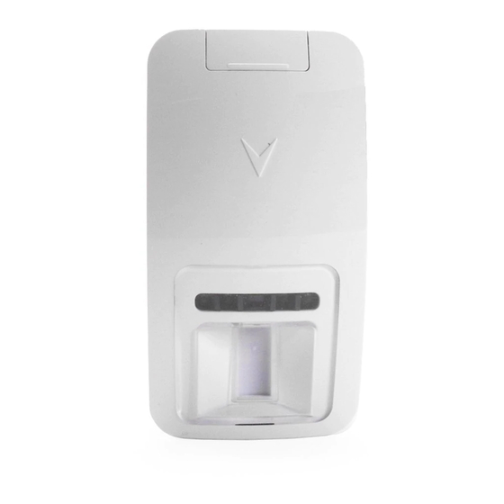
PowerG Wireless Dual Technology Mirror
PIR Motion Detector Installation
Instructions
Overview
The PG9984(P)/PG8984(P)/PG4984(P) are 2-way wireless
PIR/ Pet immune motion detectors utilizing Target Specific
Imaging™ to distinguish between human beings and pets
weighing up to 18 kg (40lb) while reduces false alarms by using
True Motion Recognition™. Built-in link quality indicators
reduce installation time by eliminating the need for the installer
to physically approach the control panel. The detectors also
have combined Fresnel and cylindrical optics that reach up to
15 meters (49 ft) and are equipped with wall creep zone protec-
tion.
Note: Pet immunity feature has not been evaluated to UL 639
or ULC-S306-03 due to the feature not being addressed in
either standard.
Device Setup
Caution! To be installed by service persons in indoor, non-haz-
ardous locations only. Risk of explosion if battery is replaced
by an incorrect type. Observe polarity when installing batteries.
Dispose of used batteries according to the manufacturer's
instructions and according to local rules and regulations. Bat-
teries are to be replaced by service persons only.
Note: To ensure the continued operation of all wireless devices
after performing a system default, a global upload of all wire-
less programming via DLS is recommended before defaulting
the system. After completing the system default, download the
wireless programming.
Legend
A
D
E
F
B
C
A. Screw Cover
B. LED
C. PIR Optical window
D. Enroll button (use a screwdriver to press the recessed but-
ton)
E. Battery
F.
Tamper switch
G. Horizontal view of coverage area
H. Vertical view of coverage area
I.
Microwave coverage
Note: Back tamper switch is required for UL commercial bur-
glary installations.
Install the battery
1
2
3
4
1. On the indicated location, lift the screw cover upward using
your thumb.
2. Loosen the screw and open the cover in the direction shown
by the arrow.
3. Insert a screwdriver into the slot shown and then push down-
ward to separate the base from the cover.
4. Insert battery while observing polarity.
Note: When manually programming wireless devices, if a
device has been powered up for more than 48 hours it cannot be
enrolled into the system until the device has been tampered and
restored. When programming the panel using the Quick Enroll
procedure follow the steps detailed in Enroll the Device into the
System.
Note: After restoring a low battery trouble the system may take
up to 5 minutes to clear the trouble.
Enroll the Device into the System
To quick enroll:
1. On a keypad press [*] [8] [Installer Code] [804] [000].
2. Press and hold the device enroll button until the LED lights
steady and then release the enroll button while the LED is
still lit. A confirmation message then appears on the keypad.
3. Press [*] key to confirm ID.
4. Enter [3 digit zone #].
5. Enter [3 digit zone type].
6. Enter [1 digit partition #] for all desired partitions and press
[#]. If using a menu based configuration you can scroll to the
desired partitions and press [*] to toggle the partition.
7. On an LCD keypad enter the label by using word library.
To pre-enroll:
1. Remotely configure the unique ID number into the system.
For more information see the HS2MHOST manual.
2. When on-site, press the device enroll button.
Note: If the wireless device has been powered for more then 48
hours without being enrolled, tamper and restore the device to
enroll it.
Perform a placement test
Note: Perform walktest at least once a year.
Before permanently mounting any wireless device, temporarily
mount the device and perform a Placement test.
1.
Tamper the
G
device by
opening the
cover.
2.
Restore the
tamper. The
device now
enters
Placement
I
test mode
for 15 min-
utes.
3.
Trip the
H
device and
the red LED
blinks once
to identify
that a signal
is being sent to the receiver and then blinks three times to
identify the signal strength. To perform a walk test, walk
across the far end of coverage pattern in both directions.
The following table indicates received signal strength indi-
cation.
LED response
Signal Strength
Green LED blinks
STRONG
Orange LED blinks
GOOD
Red LED blinks
POOR
No blinks
No communication
IMPORTANT! Only GOOD or STRONG signal strengths are
acceptable. If you receive a POOR signal from the device, re-
locate it and re-test until a GOOD or STRONG signal is
received.
Note: For UL/ULC installations, only STRONG signal levels
are acceptable. After installation verify the product functional-
ity in conjunction with the compatible receivers HSM2HOST9,
HS2LCDRF(P)9, HS2ICNRF(P)9 and PG9920.
Note: For detailed placement instructions refer to the control
panel Reference Guide.
Mount the Device
The PowerG Series wireless PIR Motion detectors shall be
installed and used within an environment that provides the pol-
lution degree max 2 and overvoltages category II.
• Keep away from heat sources.
• Do not expose to air drafts.
• Do not install outdoors.
• Avoid direct sunshine.
• Keep wiring away from power cables.
• Do not install behind partitions.
• Mount on solid stable surface.
Installation Notes: Do not obscure the detector field of view
with large objects, such as furniture. Install in position such that
expected intruder motion is perpendicular to the zones of detec-
tion. Mount further than 5ft. from fluorescent light fixture
employing two fluorescent tubes minimum rated 40 W.
Important! The PGx984 detector is immune to activity below
1 m (3ft) from 38 kg (85 lb) animals. Above the 1 m (3 ft)
height limit, the detector is immune to 19 kg (42 lb) animals.
Pet immunity decreases as the animal gets closer to the detec-
tor. Select a mounting location that minimizes potential close
proximity of animals.
Note: Pet immunity feature has not been verified by UL/ULC.
WARNING! To comply with FCC and IC RF exposure compli-
ance requirements, the PIR detector should be located at a dis-
tance of at least 20 cm from all persons during normal
operation. The antennas used for this product must not be co-
located or operated in conjunction with any other antenna or
transmitter.
To Mount the Device
Identify your mounting height and desired detector range.
Using the table below determine if you are to use mounting
holes x or y.
Note: Mounting flat or in a corner requires using different
mounting holes. Mount using the supplied screws.
x
x
y
y
Mounting Holes
Height
10ft 3.0m
y
y
y
y
9
2.7
y
y
y
x
8
2.4
y
y
x
x
7
2.1
y
x
x
x
6
1.8
6
9
12 15m
Range
15
30
45
60ft
Configuration
To enter the wireless configuration section enter [804][Zone
Number].
Device Toggles
[001][01]
Alarm LED - Default [Y]
Enables the devices LED to activate when an alarm
event occurs.
Supervision - Default [Y]
[001][04]
Enables supervision of the device.
Selections
Hightraffic Shutdown - Default [01]
[003]
Activating this feature helps conserve battery power
when the system is disarmed by configuring a reporting
timer. When motion is detected, the device transmits an
alarm to the receiver and will not report any further
events until the timer expires. Any motion detected
during the configured period will be reported once the
timer expires. No Delay causes the device to report an
alarm each time the detector is tripped.
[01] Detector Dis-
[02] No Delay
[03] 5 second
abled (while dis-
delay
armed)
[04] 15 second
[05] 30 second
[06] 1m delay
delay
delay
[07] 5m delay
[08] 10m delay
[09] 20m delay
[10] 60m delay
[016]
Event counter - Default [002]
Alarm activates after a configured number of events
have been detected.
Key in activities
001-002
LED Operation
LED Indications
Event
Red LED blinks
Stabilization (warm-up 60
sec)
Red LED on 0.2 sec.
Tamper open / close
Red LED blinks twice
One quad PIR detection in
diagnostic mode
Red LED on 2 sec.
Intruder alarm
Yellow LED on
AM detection – Testing
mode
Yellow LED blinks slowly (0.2
AM detection – Normal
sec. ON, 30 sec. OFF)
mode
Specifications
GENERAL
Detector Type: Dual element low-noise pyroelectric sensor
Lens Data
No. of Beam Elements: 18x3=54 far parabolic mirror seg-
ments
No. of Curtain Elements: 18
MW Coverage
Maximum: 15 m (49 ft) / 90°
Medium: 10 m (33 ft) / 90°
Minimum: 5 m (16 ft) / 90°
Note: For UL/ULC listed installations the following settings
are required:
MW coverage: Maximum
Event counter: High Sensitivity
Pet Immunity (PGx984P): Up to 18 kg (40 lb)
ELECTRICAL
Sensor Type: K Band Doppler module: 24 GHz
Internal Battery: 3V Lithium battery, type CR-123A con-
sumer grade, UL or equivalent listed, RoHS compliant. Dispose
of used batteries according to local regulations.
Note: For UL installations use Panasonic, Sanyo, GP or Varta
only.
Nominal Battery Capacity:1450 mA/h
Battery Life (for typical use): minimum one year, typical 5-8
years (not verified by UL/ULC)
Low Battery Threshold: 2.5 V
FUNCTIONAL
True Motion Event Verification: 2 remote selections - 1
(OFF) or 2 (ON) motion events
Verification Alarm Period: 2 seconds
WIRELESS
Frequency Band (MHz): CE Listed PG4984: 433MHz; CE/
EN listed PG8984: 868MHz; FCC/IC/UL/ULC listed PG9984:
912-919 MHz
Communication Protocol: PowerG
Supervision: Signaling at 4-min. intervals
Tamper Alert: Reported when a tamper event occurs and in
any subsequent message, until the tamper switch is restored
MOUNTING
Height: 1.8 – 3.0 m (6 - 10 ft)
Installation Options - Surface or corner
ACCESSORIES
PGBRACKET-1: Surface mounted swivel bracket, adjustable
30° down and 45° left/45° right.
PGBRACKET-2: PGBRACKET-1 with a corner adapter
PGBRACKET-3: PGBRACKET-1 with a ceiling adapter
Note: UL did not evaluate the product with the use of brackets.
ENVIRONMENTAL
RFI Protection: > - 20 V/m up to 2000 MHz, excluding inband
frequencies
Temperature range: -10ºC to +55ºC (UL/ULC only verified the
range 0ºC-49ºC)
Relative Humidity: up to max. 93%RH, non-condensing
PHYSICAL
Size (H x W x D): 115 x 60 x 48 mm (4-1/2 x 2-5/16 x 1-15/
16")
Weight (with battery): 90 g (3oz).
Color: White
COMPATIBLE RECEIVERS
433MHz Band: HSM2HOST4; HS2LCDRF(P)4;HS2IC-
NRF(P)4; PG4920
868MHz Band: HSM2HOST8; HS2LCDRF(P)8; HS2IC-
NRF(P)8;PG8920
912-919MHz Band: HSM2HOST9; HS2LCDRF(P)9; HS2IC-
NRF(P)9; PG9920
Note: Only devices operating in band 912-919MHz are UL/
ULC listed.
UL/ULC Notes
Only models PG9984, PG9984P operating in the frequency
band 912-919MHz are UL/ULC listed. The PG9984, PG9984P
has been listed by UL for commercial and residential burglary
applications and by ULC for residential burglary applications in
accordance with the requirements in the Standards UL 639 and
ULC-S306 for Intrusion Detection Units.
For UL/ULC installations use these device only in conjunction
with compatible DSC wireless receivers: HSM2HOST9,
HS2LCDRF(P)9, HS2ICNRF(P)9 and PG9920. After installa-
tion verify the product functionality in conjunction with the
compatible receiver used.
Europe: The PG4984/PG4984P and PG8984/
PG8984P are compliant with the RTTE require-
ments - Directive 1999/5/EC of the European Par-
liament and of the Council of 9 March 1999. The
PG8984/PG8984P is certified to the following standards:
EN50131-2-4, EN50131-1 GRADE 2, CLASS II, EN50131-6
Type C. Certification covers only the 868 MHz variant of this
product. According to EN 50131-1:2006 and A1:2009, this
equipment can be applied in installed systems up to and includ-
ing Security Grade 2, Environmental Class II. UK: The PG8984
is suitable for use in systems installed to conform to
PD6662:2010 at Grade 2 and environmental class 2 BS8243
The Power G peripheral devices have two- way communication
functionality, providing additional benefits as described in the
technical brochure. This functionality has not been tested to
comply with the respective technical requirements and should
therefore be considered outside the scope of the product's certi-
fication.
PG9984(P)/PG8984(P)/PG4984(P)
Instructions d'installation du détecteur de
mouvement IPR, miroir, double
technologie sans fil PowerG
Vue d'ensemble
Les PG9984(P)/PG8984(P)/PG4984(P) sont des détecteurs de
mouvement IPR/insensibles aux animaux, bidirectionnels, sans
fil, qui arrivent à faire la distinction entre des êtres humains et
des animaux d'un poids de 18 kg (40lb) max. grâce à la technol-
ogie Target Specific Imaging™ tout en réduisant les fausses
alarmes grâce à la technologie True Motion Recognition™. Les
indicateurs de qualité de liaison intégrés réduisent les temps
d'installation en supprimant la nécessité de l'installateur d'être
physiquement à proximité de la centrale. Les détecteurs sont
munis également d'optiques combinées cylindriques et de Fres-
nel qui atteignent une portée de 15 mètres (49 pieds) max. et
possèdent une détection au ras du mur.
Remarque : La fonction d'insensibilité aux animaux n'a pas été
évaluée pour les normes UL 639 ou ULC-S306-03 parce qu'elle
n'est pas abordée par les deux normes.
Réglage du dispositif
Advertisement

Related Manuals for DSC PG9984(P)


Summary of Contents for DSC PG9984(P)
- Page 1 AM detection – Normal instructions and according to local rules and regulations. Bat- mounting holes. Mount using the supplied screws. with compatible DSC wireless receivers: HSM2HOST9, Note: If the wireless device has been powered for more then 48 sec. ON, 30 sec. OFF) mode teries are to be replaced by service persons only.
-
Page 2: Récepteurs Compatibles
Type de détecteur : Détecteur pyroélectrique à deux éléments, Pour les installations UL/ULC, utilisez uniquement ces disposi- sabotage. Le faible bruit tifs en association avec des récepteurs sans fil DSC compatibles dispositif A. Couvercle à vis Information sur la lentille : HSM2HOST9, HS2LCDRF(P)9, HS2ICNRF(P)9 et PG9920. -
Page 3: Montaje
D. Botón de asociar (use un destornillador para presionar el Para instalaciones UL/ULC use estos dispositivos solamente de prueba de mento dual botón embutido) con receptores inalámbricos DSC compatibles: HSM2HOST9, colocación Datos de la lente E. Batería HS2LCDRF(P)9, HS2ICNRF(P)9 y PG9920. Después de la durante 15 N.º... -
Page 4: Receptores Compatíveis
GERAL Bloqueie o Para instalações UL/ULC, use estes dispositivos apenas em dispositivo Tipo de Detetor: Sensor piroelétrico de baixo ruído de ele- conjunto com receptores sem fio compatíveis com DSC: abrindo a mento duplo HSM2HOST9, HS2LCDRF(P)9, HS2ICNRF(P)9 e PG9920. tampa. - Page 5 (c) Backup Copy - You may make back-up copies of the adquisición, instalación, operación o fallo de este producto. Si le produit logiciel DSC (« PRODUIT LOGICIEL » ou « LOGICIEL ») a été conçu WARRANTY OR LIABILITY CONCERNING THIS SOFTWARE PRODUCT.
- Page 6 (EULA). Se tal acontecer, V.Exa. deverá destruir todas as cópias do PROGRAMA e acuerdo o contrato previo. Si no está de acuerdo con los términos de este EULA, DSC características operativas del HARDWARE, o de problemas en la interacción del houver fontes de calor intencionais ou não-intencionais dentro ou próximas da área de...