
Related Manuals for RITE-HITE Rave


Summary of Contents for RITE-HITE Rave
- Page 1 INSTALLATION AND OWNER’S MANUAL THIS MANUAL COVERS ALL UNITS SHIPPED JUNE 2012 TO DATE PRINTED IN U.S.A. PUBLICATION NO. RAVE REV. 3 RITE-HITE PRINT SHOP © JUNE 2013...
-
Page 2: Table Of Contents
™ Fan from RITE-HITE IMPORTANT Read and understand contents of this manual prior to installation or operation of this equipment. ® For best results, have this product serviced by your authorized RITE-HITE Representative. NOTICE TO USER ® Your local RITE-HITE Representative provides the Planned Maintenance Program (P.M.P.) which can be fitted to your... -
Page 3: Declaration Of Conformity
Milwaukee, WI 56223 USA Hereby declares that the below mentioned products Ceiling Fan Type : Revolution HVLS Fan and Rave HVLS Fan Rouge HVLS Fan and Renegade HVLS Fan Year : 2012 Comply with all relevant requirements of the Machine Directive. - Page 4 RAVE ™ NOTES Pub. No. RAVE Rev. 3 - © JUNE 2013...
-
Page 5: Safety
® RITE-HITE Corporation does not recommend any particular lockout device, but recommends the utilization of a device that meets OSHA standards (refer to OSHA regulation 1910.147). RITE-HITE ® Corporation also recommends the review and implementation of an entire safety program for the Control of Hazardous Energy (Lockout/Tagout). -
Page 6: General Information
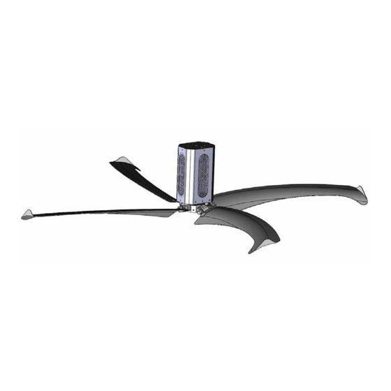
The Rave Fan is a high-volume/low-speed (HV/LS) industrial fan that provides more consistent air circulation and ventilation with better energy efficiency than traditional high-speed ceiling fans or industrial floor fans. SERIAL LABEL Pub. No. RAVE Rev. 3 - © JUNE 2013... - Page 7 RAVE ™ SAFETY LABELS The safety labels have specific placement and must be replaced if they are defaced or removed for any reason. IMPORTANT DANGER Pub. No. RAVE Rev. 3 - © JUNE 2013...
- Page 8 Incoming fan power and motor cable must be in separate conduit, run at least 6" (153mm) apart. Motor cable must contain stranded copper wire. Motor cable may not exceed 200' (60m). See owners manual for specifications. Pub. No. RAVE Rev. 3 - © JUNE 2013...
- Page 9 Incoming fan power and motor cable must be in separate conduit, run at least 6" (153mm) apart. 53850606-6 DANGER HIGH VOLTAGE Disconnect power before servicing! 53850606-7 www.ritehitefans.com Milwaukee WI,0 53223 414-355-2600 Patents Pending Pub. No. RAVE Rev. 3 - © JUNE 2013...
-
Page 10: Specifications
Up to 5 mph (2.24 m/s) at full speed Controls: Variable speed Mounting Heights: 10 to 80 ft (3.0 to 24.4 m) from finished floor to bottom of blade Weight: 150 lb (68 kg) Pub. No. RAVE Rev. 3 - © JUNE 2013... -
Page 11: Fan Dimensions
RAVE ™ FAN DIMENSIONS Pub. No. RAVE Rev. 3 - © JUNE 2013... -
Page 12: Components And Tools
(4) 10 AWG electrical terminals for motor terminations (1) Torpedo Level If you are mounting to support angles that span building joists, you will also need a drill and a 1/2 in. drill bit. Pub. No. RAVE Rev. 3 - © JUNE 2013... -
Page 13: Mounting Of The Fan
Table 4 MINIMUM CLEARANCE DIAMETER DIMENSION AT FULL RPM ft (mm) ft (mm) 8 (2440) 2 (610) 10 (3050) 3 (915) 12 (3660) 3 (915) Pub. No. RAVE Rev. 3 - © JUNE 2013... -
Page 14: I-Beam And Truss Mounting
(see Figure 6). Securely mount the angles to the building joists to ensure the angles cannot move. Use a level to ensure the extension tube is hanging vertical. Figure 6 Figure 5 Pub. No. RAVE Rev. 3 - © JUNE 2013... - Page 15 NOTE: When the truss kit is ordered from Rite-Hite, the standard I-beam ceiling bracket will not be provided. Figure 7 Pub. No. RAVE Rev. 3 - © JUNE 2013...
-
Page 16: Laminated Beam Kit Installation
1. Through-bolt the laminated beam brackets with one bracket on each side of the laminated (or concrete) beam. 2. Attach the standard ceiling mounting bracket to this bracket in the normal manner. Pub. No. RAVE Rev. 3 - © JUNE 2013... -
Page 17: Motor Bracket
5. If the fan assembly is mounted directly to the ceiling bracket without an extension tube, use four 1/2 x 1-1/2 in. Grade 8 bolts (not provided) to bolt the brackets together properly. Pub. No. RAVE Rev. 3 - © JUNE 2013... - Page 18 3. If installing with adjustable-length extension tubes, use a third safety cable to secure the center bolted joint of the extension tubes. Secure the safety cables with the provided clamps (see Figure 9). Pub. No. RAVE Rev. 3 - © JUNE 2013...
-
Page 19: Installation
1 – Cable Clamp Nuts 2 – Turnback 5. Tighten the stabilization cables one turn past hand-tight. 6. Install stabilization cable clamp nuts away from turnback, as shown in Figure 11. Pub. No. RAVE Rev. 3 - © JUNE 2013... - Page 20 Replacement all directions. blades are provided in pairs. 2. Make fine adjustments with the stabilization cables. 3. After run/test, go back and test level and cable tension. Pub. No. RAVE Rev. 3 - © JUNE 2013...
- Page 21 The standard control box for the Rave ™ Fan is 14 in. W x 16 in. H x 8 in. D (355 mm W x 405 mm H x 203 mm D). Pub. No. RAVE Rev. 3 - © JUNE 2013...
-
Page 22: Speed Control Station
1 LED 10Hz A077 2 LEDs 18Hz A076 A072 3 LEDs 26Hz A075 4 LEDs 35Hz A074 A071 5 LEDs 44Hz A073 6 LEDs 52Hz A072 A070 7 LEDs 60Hz A071 Pub. No. RAVE Rev. 3 - © JUNE 2013... -
Page 23: Motor Wiring
MAY NOT share the same conduit. The conduit with the incoming power and the conduit with the power going to the motor should be separated by a minimum of 6 in. (150 mm). Pub. No. RAVE Rev. 3 - © JUNE 2013... -
Page 24: Field Wiring
480V 2HP (1.5 kW) 480V 1HP (0.75 kW) 575V 2HP (1.5 kW) 575V 1HP (0.75 kW) 230V 2HP (1.5 kW) 120V 1HP (0.75 kW) 230V 1HP (0.75 kW) 230V 1HP (0.75 kW) Pub. No. RAVE Rev. 3 - © JUNE 2013... - Page 25 20 LB-IN (2.3 NM) MAX TERMINAL TORQUE 20 LB-IN (2.3 NM) MAX DO NOT USE SOLID CORE WIRING OF ANY SIZE OR INSULATION CLASS FOR CONTROLLER OUTPUT/MOTOR LEADS. ALLEN BRADLEY POWERFLEX4 Pub. No. RAVE Rev. 3 - © JUNE 2013...
-
Page 26: Fan Controls Layout
RAVE ™ Pub. No. RAVE Rev. 3 - © JUNE 2013... - Page 27 RAVE ™ Revolution & Rave™ Panels Rave™ Panels Pub. No. RAVE Rev. 3 - © JUNE 2013...
-
Page 28: Control Box Wiring
RAVE ™ CONTROL BOX WIRING Pub. No. RAVE Rev. 3 - © JUNE 2013... -
Page 29: Schnieder Emc Plate And Shielded Cable
EMC plate. NOTICE The shielded motor cable should be connected to ground at both the motor and control box. Figure 16 WIRING WITH SHIELDED CABLE Figure 17 Pub. No. RAVE Rev. 3 - © JUNE 2013... -
Page 30: Control Box Mounting
An authorized electrician must verify the electrical system (ground system, insulation, etc.) before the fan is put into operation. The customer should record and store the verification data. STOP CIRCUIT FOR FANS: SCHNEIDER VFD Figure 18 Pub. No. RAVE Rev. 3 - © JUNE 2013... -
Page 31: Motor Wiring Cont. / Annual Planned Maintenance
(see page 5). tagout procedures (see page 5). • Use compressed air at 90 – 100 psi (621 – 689 kPa) to blow loose debris and dust out of the VFD enclosure. Pub. No. RAVE Rev. 3 - © JUNE 2013... -
Page 32: Fan Noise
• The attachment hardware sometimes causes vibration noise. Take the necessary steps to identify and eliminate the vibration. Pub. No. RAVE Rev. 3 - © JUNE 2013... - Page 33 (d003) does not exceed the drive rated current times the derate percentage indicated below. When increasing carrier frequency (SFr) on a Schneider drive, limit maximum speed (HSP), such that motor current (LCr) does not exceed the derated drive output current. Pub. No. RAVE Rev. 3 - © JUNE 2013...
-
Page 34: Troubleshooting
FORWARD, and REVERSE. With output wires disconnected, repeat the measurements at the terminals on the back of the speed controller. If correct voltages are still not measured, you may have a bad speed controller. Call Rite-Hite Customer Service. If correct voltages are measured with the output wires disconnected, a wiring error or short in the cable is likely causing the voltage to drop. - Page 35 Using a DMM, step through each of the seven speed settings and verify the proper input states. Check for swapped wires if the input states do not match the following table. Pub. No. RAVE Rev. 3 - © JUNE 2013...
- Page 36 P038 = 4 A051 = 4 A052 = 4 A053 = 4 Verify the following Schneider parameter settings: FUn- PSS- PS2 = L4H/LI4 FUn- PSS- PS4 = L3H/LI3 FUn- PSS- PS8 = L2H/LI2 Pub. No. RAVE Rev. 3 - © JUNE 2013...
- Page 37 Figure 15, settings should be already set to the parameters below. Menu Parameter Description Value FUn- PSS-PS2 Preset Speed Bit FUn- PSS-PS4 Preset Speed Bit FUn- PSS-PS8 Preset Speed Bit I-O- Reverse Direction Pub. No. RAVE Rev. 3 - © JUNE 2013...
- Page 38 8' (2440 mm) fan = 75 rpm If the fan rotates at a different speed than above, check the gearbox label to ensure the wrong size blades were not installed on the fan. Pub. No. RAVE Rev. 3 - © JUNE 2013...
- Page 39 Consult factory if irregular noises are present. Incoming / Outgoing wiring not separated Run incoming wire and outgoing wiring in separate conduit a minimum of 6 in. (150 mm) apart. Pub. No. RAVE Rev. 3 - © JUNE 2013...
-
Page 40: Parts
RAVE ™ PARTS Pub. No. RAVE Rev. 3 - © JUNE 2013... -
Page 41: Pub. No. Rave Rev. 3 - © June
RAVE ™ Pub. No. RAVE Rev. 3 - © JUNE 2013... - Page 42 RAVE ™ Pub. No. RAVE Rev. 3 - © JUNE 2013...
- Page 43 RAVE ™ Pub. No. RAVE Rev. 3 - © JUNE 2013...
- Page 44 RAVE ™ Pub. No. RAVE Rev. 3 - © JUNE 2013...
- Page 45 RAVE ™ Pub. No. RAVE Rev. 3 - © JUNE 2013...
- Page 46 RAVE ™ Pub. No. RAVE Rev. 3 - © JUNE 2013...
- Page 47 RAVE ™ Pub. No. RAVE Rev. 3 - © JUNE 2013...
- Page 48 RAVE ™ Pub. No. RAVE Rev. 3 - © JUNE 2013...
- Page 49 RAVE ™ NOTES Pub. No. RAVE Rev. 3 - © JUNE 2013...
- Page 50 RAVE ™ NOTES Pub. No. RAVE Rev. 3 - © JUNE 2013...
- Page 52 Periodic lubrication and ® ® adjustment is the sole responsibility of the owner. This warranty is RITE-HITE exclusive warranty. RITE-HITE EXPRESSLY DISCLAIMS ALL IMPLIED WARRANTIES INCLUDING THE IMPLIED WARRANTIES OF MERCHANTABILITY AND FITNESS. Non- ®...
Need help?
Do you have a question about the Rave and is the answer not in the manual?
Questions and answers