TP-Link T2600G-28TS User Manual
Jetstream gigabit l2 managed switch
Hide thumbs
Also See for T2600G-28TS:
- Reference manual (450 pages) ,
- User manual (355 pages) ,
- Installation manual (32 pages)

Subscribe to Our Youtube Channel
Related Manuals for TP-Link T2600G-28TS


Summary of Contents for TP-Link T2600G-28TS
- Page 1 T2600G-28TS (TL-SG3424) T2600G-52TS (TL-SG3452) JetStream Gigabit L2 Managed Switch REV1.0.0 1910011257...
-
Page 2: Fcc Statement
Specifications are subject to change without notice. is a registered trademark of TP-LINK TECHNOLOGIES CO., LTD. Other brands and product names are trademarks or registered trademarks of their respective holders. No part of the specifications may be reproduced in any form or by any means or used to make any derivative such as translation, transformation, or adaptation without permission from TP-LINK TECHNOLOGIES CO., LTD. -
Page 3: Safety Information
Safety Information When product has power button, the power button is one of the way to shut off the product; When there is no power button, the only way to completely shut off power is to disconnect the product or the power adapter from the power source. Don’t disassemble the product, or make repairs yourself. -
Page 4: Table Of Contents
CONTENTS Package Contents ..........................1 Chapter 1 About this Guide ......................2 Intended Readers ......................2 Conventions ........................2 Overview of This Guide ....................2 Chapter 2 Introduction ........................6 Overview of the Switch ....................6 Appearance Description ....................6 2.2.1 Front Panel ...................... - Page 5 SDM Template ......................42 4.5.1 SDM Template Config ..................42 Chapter 5 Switching ........................44 Port ..........................44 5.1.1 Port Config ......................44 5.1.2 Port Mirror......................45 5.1.3 Port Security ...................... 47 5.1.4 Port Isolation ..................... 49 5.1.5 Loopback Detection ..................50 LAG ..........................
- Page 6 6.7.2 Port Enable ......................85 6.7.3 VLAN Mapping ....................85 GVRP ........................... 88 Private VLAN ........................ 91 6.9.1 PVLAN Config ....................93 6.9.2 Port Config ......................94 6.10 Application Example for Private VLAN ................ 95 Chapter 7 Spanning Tree ......................98 STP Config .........................
- Page 7 8.2.7 Profile Binding ....................148 8.2.8 Packet Statistics ....................150 Multicast Table ......................151 8.3.1 IPv4 Multicast Table ..................151 8.3.2 Static IPv4 Multicast Table ................152 8.3.3 IPv6 Multicast Table ..................153 8.3.4 Static IPv6 Multicast Table ................154 Chapter 9 Routing ........................
- Page 8 11.2.5 Extend-IP ACL ....................184 11.3 Policy Config ......................185 11.3.1 Policy Summary ....................185 11.3.2 Policy Create ....................186 11.3.3 Action Create ....................186 11.4 ACL Binding........................ 187 11.4.1 Binding Table ....................188 11.4.2 Port Binding ..................... 189 11.4.3 VLAN Binding ....................
- Page 9 13.1.3 SNMP Group ....................227 13.1.4 SNMP User ...................... 228 13.1.5 SNMP Community ................... 230 13.2 Notification ........................232 13.3 RMON......................... 234 13.3.1 Statistics ......................235 13.3.2 History ......................236 13.3.3 Event ....................... 237 13.3.4 Alarm Config ....................238 Chapter 14 LLDP .......................... 240 14.1 Basic Config .......................
- Page 10 Appendix B. Glossary ......................266...
-
Page 11: Package Contents
One JetStream Gigabit L2 Managed Switch One power cord Two mounting brackets and other fittings Installation Guide Resource CD for T2600G-28TS/T2600G-52TS, including: This User Guide • CLI Reference Guide • SNMP Mibs • 802.1X Client Software and its User Guide •... -
Page 12: Chapter 1 About This Guide
JetStream Gigabit L2 Managed Switch without any explanation. Tips: The T2600G-28TS and T2600G-52TS are sharing this User Guide. They just differ in the number of LED indicators and ports. For simplicity, we will take T2600G-28TS for example throughout this Guide. However, differences with significance will be presented with figures or notes as to attract your attention. - Page 13 Chapter Introduction Chapter 4 System This module is used to configure system properties of the switch. Here mainly introduces: System Info: Configure the description, system time and network parameters of the switch. User Management: Configure the user name and password ...
- Page 14 Chapter Introduction Chapter 8 Multicast This module is used to configure multicast function of the switch. Here mainly introduces: IGMP Snooping: Configure global parameters of IGMP Snooping function, port properties, VLAN and multicast VLAN. MLD Snooping: Configure global parameters of MLD ...
- Page 15 Chapter Introduction Chapter 12 Network Security This module is used to configure the protection measures for the network security. Here mainly introduces: IP-MAC Binding: Bind the IP address, MAC address, VLAN ID and the connected Port number of the Host together. DHCP Snooping: DHCP Snooping functions to monitor the ...
-
Page 16: Chapter 2 Introduction
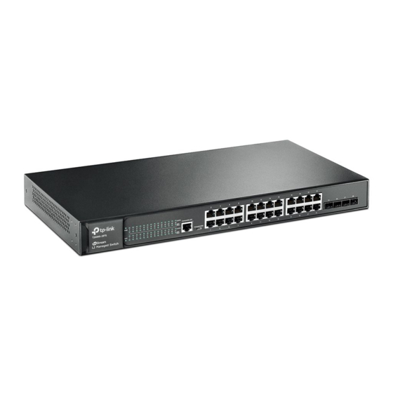
2.2 Appearance Description 2.2.1 Front Panel The front panel of T2600G-28TS is shown as Figure 2-1. Figure 2-1 Front Panel of T2600G-28TS The following parts are located on the front panel of T2600G-28TS: LEDs Name Status Indication The switch is powered on. - Page 17 10/100/1000Mbps RJ45 port has a corresponding 1000Mbps LED and Link/Act LED. SFP Port Designed to install the SFP module. T2600G-28TS features 4 individual SFP ports and supports 1000M SFP module connection only. The front panel of T2600G-52TS is shown as Figure 2-2.
-
Page 18: Rear Panel
T2600G-28TS T2600G-52TS 2.2.2 Rear Panel The rear panel of T2600G-28TS/T2600G-52TS features a Kensington security slot, a Grounding Terminal (marked with ) and a power socket. Figure 2-3 Rear Panel Kensington Security Slot: Secure the lock (not provided) into the security slot to prevent the... - Page 19 Grounding Terminal: The switch already comes with lightning protection mechanism. You can also ground the switch through the PE (Protecting Earth) cable of AC cord or with Ground Cable. AC Power Socket: Connect the female connector of the power cord here, and the male connector to the AC power outlet.
-
Page 20: Chapter 3 Login To The Switch
Chapter 3 Login to the Switch 3.1 Login 1) To access the configuration utility, open a web-browser and type in the default address http://192.168.0.1 in the address field of the browser, then press the Enter key. Figure 3-1 Web-browser Tips: To log in to the switch, the IP address of your PC should be set in the same subnet addresses of the switch. -
Page 21: Configuration
3.2 Configuration After a successful login, the main page will appear as Figure 3-3, and you can configure the function by clicking the setup menu on the left side of the screen. Figure 3-3 Main Setup-Menu Note: Clicking Apply can only make the new configurations effective before the switch is rebooted. If you want to keep the configurations effective even the switch is rebooted, please click Save Config. -
Page 22: Chapter 4 System
Chapter 4 System The System module is mainly for system configuration of the switch, including four submenus: System Info, User Management, System Tools, Access Security and SDM Template. 4.1 System Info The System Info, mainly for basic properties configuration, can be implemented on System Summary, Device Description, System Time, Daylight Saving Time and System IPv6 pages. - Page 23 When the cursor moves on the port, the detailed information of the port will be displayed. Figure 4-2 Port Information Port Info Port: Displays the port number of the switch. Type: Displays the type of the port. Rate: Displays the maximum transmission rate of the port. Status: Displays the connection status of the port.
-
Page 24: Device Description
4.1.2 Device Description On this page you can configure the description of the switch, including device name, device location and system contact. Choose the menu System→System Info→Device Description to load the following page. Figure 4-4 Device Description The following entries are displayed on this screen: Device Description ... -
Page 25: Daylight Saving Time
The following entries are displayed on this screen: Time Info Current System Time: Displays the current date and time of the switch. Current Time Source: Displays the current time source of the switch. Time Config Manual: When this option is selected, you can set the date and time manually. -
Page 26: System Ipv6
The following entries are displayed on this screen: DST Config DST Status: Enable or disable the DST. Predefined Mode: Select a predefined DST configuration. USA: Second Sunday in March, 02:00 ~ First Sunday in November, 02:00. Australia: First Sunday in October, 02:00 ~ First Sunday in ... - Page 27 3. Flexible extension headers: IPv6 cancels the Options field in IPv4 packets but introduces multiple extension headers. In this way, IPv6 enhances the flexibility greatly to provide scalability for IP while improving the handling efficiency. The Options field in IPv4 packets contains 40 bytes at most, while the size of IPv6 extension headers is restricted by that of IPv6 packets.
- Page 28 Note: Two colons (::) can be used only once in an IPv6 address, usually to represent the longest successive hexadecimal fields of zeros. If two colons are used more than once, the device is unable to determine how many zeros double-colons represent when converting them to zeros to restore a 128-bit IPv6 address.
- Page 29 Type Format Prefix (binary) IPv6 Prefix ID Multicast address 11111111 FF00::/8 Anycast addresses are taken from unicast Anycast address address space and are not syntactically distinguishable from unicast addresses. Table 4-1 Mappings between address types and format prefixes 3. IPv6 Unicast Address: IPv6 unicast address is an identifier for a single interface.
- Page 30 The figure below shows the structure of a global unicast address. Figure 4-7 Global Unicast Address Format Link-local address A link-local address is an IPv6 unicast address that can be automatically configured on any interface using the link-local prefix FE80::/10 (1111 1110 10) and the interface identifier in the modified EUI-64 format.
- Page 31 packet header, on the local link. After the source node receives the neighbor advertisement, the source node and destination node can communicate. Neighbor advertisement messages are also sent when there is a change in the link-layer address of a node on a local link. Address Resolution The address resolution procedure is as follows: Node A multicasts an NS message.
- Page 32 2. IPv6 Router Advertisement Message Router advertisement (RA) messages, which have a value of 134 in the Type field of the ICMP packet header, are periodically sent out each configured interface of an IPv6 router. RA messages typically include the following information: One or more onlink IPv6 prefixes that nodes on the local link can use to automatically ...
- Page 33 You can configure the system’s administrative IPv6 address on this page. Choose the menu System →System Info →System IPv6 to load the following page. Figure 4-9 System IPv6 The following entries are displayed on this screen: Global Config IPv6: Enable/Disable IPv6 function globally on the switch.
- Page 34 Link-local Address: Enter a link-local address. Status: Displays the status of the link-local address. Normal: Indicates that the link-local address is normal. Try: Indicates that the link-local address may be newly configured. Repeat: Indicates that the link-local address is duplicate. It is ...
-
Page 35: User Management
Status: Displays the status of the global address. Normal: Indicates that the global address is normal. Try: Indicates that the global address may be newly configured. Repeat: Indicates that the corresponding address is duplicate. It is illegal to access the switch using this address. Tips: After adding a global IPv6 address to your switch manually here, you can configure your PC’s global IPv6 address in the same subnet with the switch and login to the switch via its global IPv6... -
Page 36: System Tools
Choose the menu System→User Management→User Config to load the following page. Figure 4-11 User Config The following entries are displayed on this screen: User Info User Name: Create a name for users’ login. Access Level: Select the access level to login. Guest: Guest only can view the settings without the right to edit ... -
Page 37: Boot Config
4.3.1 Boot Config On this page you can configure the boot file of the switch. When the switch is powered on, it will start up with the startup image. If it fails, it will try to start up with the backup image. If this fails too, you will enter into the bootutil menu of the switch. -
Page 38: Config Restore
4.3.2 Config Restore On this page you can upload a backup configuration file to restore your switch to this previous configuration. Choose the menu System→System Tools→Config Restore to load the following page. Figure 4-13 Config Restore The following entries are displayed on this screen: Config Restore ... -
Page 39: Firmware Upgrade
4.3.4 Firmware Upgrade The switch system can be upgraded via the Web management page. To upgrade the system is to get more functions and better performance. Go to http://www.tp-link.com to download the updated firmware. Choose the menu System→System Tools→Firmware Upgrade to load the following page. -
Page 40: System Reboot
is not checked, the uploaded firmware file will take place of the Backup Image. To start with the uploaded firmware, you should exchange the Next Startup Image and Backup Image in Boot Config and reboot the switch. Note: Upgrading the firmware will only upgrade the backup image. You are suggested to backup the configuration before upgrading. -
Page 41: Access Security
4.4 Access Security Access Security provides different security measures for the remote login so as to enhance the configuration management security. It can be implemented on Access Control, HTTP Config, HTTPS Config, SSH Config and Telnet Config pages. 4.4.1 Access Control On this page you can control the users logging on to the Web management page to enhance the configuration management security. -
Page 42: Http Config
IP Address & Mask These fields is available to configure only when IP-based mode is selected. Only the users within the IP-range you set here are allowed for login. MAC Address: The field is available to configure only when MAC-based mode is selected. -
Page 43: Https Config
Admin Number: Enter the maximum number of the users logging on to the Web management page as Admin. Guest Number: Enter the maximum number of the users logging on to the Web management page as Guest. 4.4.3 HTTPS Config SSL (Secure Sockets Layer), a security protocol, is to provide a secure connection for the application layer protocol (e.g. - Page 44 Choose the menu System→Access Security→HTTPS Config to load the following page. Figure 4-20 HTTPS Config The following entries are displayed on this screen Global Config HTTPS: Select Enable/Disable the HTTPS function on the switch. SSL Version 3: Enable or Disable Secure Sockets Layer Version 3.0. By default, it’s enabled.
-
Page 45: Ssh Config
CipherSuite Config RSA_WITH_RC4_128_MD5: Key exchange with RC4 128-bit encryption and MD5 for message digest. By default, it’s enabled. RSA_WITH_RC4_128_SHA: Key exchange with RC4 128-bit encryption and SHA for message digest. By default, it’s enabled. RSA_WITH_DES_CBC_SHA: Key exchange with DES-CBC for message encryption and SHA for message digest. - Page 46 information security and powerful authentication when you log on to the switch remotely through an insecure network environment. It can encrypt all the transmission data and prevent the information in a remote management being leaked. Comprising server and client, SSH has two versions, V1 and V2 which are not compatible with each other.
- Page 47 Idle Timeout: Specify the idle timeout time. The system will automatically release the connection when the time is up. The default time is 120 seconds. Max Connect: Specify the maximum number of the connections to the SSH server. No new connection will be established when the number of the connections reaches the maximum number you set.
- Page 48 Application Example 1 for SSH: Network Requirements 1. Log on to the switch via password authentication using SSH and the SSH function is enabled on the switch. 2. PuTTY client software is recommended. Configuration Procedure 1. Open the software to log on to the interface of PuTTY. Enter the IP address of the switch into Host Name field;...
- Page 49 Application Example 2 for SSH: Network Requirements 1. Log on to the switch via key authentication using SSH and the SSH function is enabled on the switch. 2. PuTTY client software is recommended. Configuration Procedure 1. Select the key type and key length, and generate SSH key. Note: The key length is in the range of 512 to 3072 bits.
- Page 50 2. After the key is successfully generated, please save the public key and private key to the computer. 3. On the Web management page of the switch, download the public key file saved in the computer to the switch. Note: The key type should accord with the type of the key file.
- Page 51 4. After the public key and private key are downloaded, please log on to the interface of PuTTY and enter the IP address for login. 5. Click Browse to download the private key file to SSH client software and click Open.
-
Page 52: Telnet Config
After successful authentication, please enter the login user name. If you log on to the switch without entering password, it indicates that the key has been successfully downloaded. 4.4.5 Telnet Config On this page you can Enable/Disable Telnet function globally on the switch. Choose the menu System→Access Security→Telnet Config to load the following page. - Page 53 Choose the menu System→SDM Template→SDM Template Config to load the following page. Figure 4-23 SDM Template Config Select Options Current Template Displays the SDM template currently in use. Next Template ID: Displays the SDM template that will become active after a reboot. Select Next Configure the SDM template that will become active after the next Template:...
-
Page 54: Chapter 5 Switching
Chapter 5 Switching Switching module is used to configure the basic functions of the switch, including four submenus: Port, LAG, Traffic Monitor and MAC Address. 5.1 Port The Port function, allowing you to configure the basic features for the port, is implemented on the Port Config, Port Mirror, Port Security, Port Isolation and Loopback Detection pages. -
Page 55: Port Mirror
Status: Allows you to Enable/Disable the port. When Enable is selected, the port/LAG can forward the packets normally. Speed: Select the Speed mode for the port. The device connected to the switch should be in the same Speed and Duplex mode with the switch. - Page 56 Source: Displays the mirrored ports. Operation: You can configure the mirror session by clicking Edit, or clear the mirror session configuration by clicking the Clear. Click Edit to display the following figure. Figure 5-3 Port Mirror Config The following entries are displayed on this screen: Destination Port ...
-
Page 57: Port Security
Egress: Select Enable/Disable the Egress feature. When the Egress is enabled, the outgoing packets sent by the mirrored port will be copied to the mirroring port. LAG: Displays the LAG number which the port belongs to. The LAG member cannot be selected as the mirrored port or mirroring port. Note: The LAG member cannot be selected as the mirrored port or mirroring port. - Page 58 Choose the menu Switching→Port→Port Security to load the following page. Figure 5-4 Port Security The following entries are displayed on this screen: Port Security Select: Select the desired port for Port Security configuration. It is multi-optional. Port: Displays the port number. Max Learned MAC: Specify the maximum number of MAC addresses that can be learned on the port.
-
Page 59: Port Isolation
Status: Select Enable/Disable the Port Security feature for the port. Note: The Port Security function is disabled for the LAG port member. Only the port is removed from the LAG, will the Port Security function be available for the port. 5.1.4 Port Isolation Port Isolation provides a method of restricting traffic flow to improve the network security by forbidding the port to forward packets to the ports that are not on its forward portlist. -
Page 60: Loopback Detection
Click Edit to display the following figure. Figure 5-6 Port Isolation Config 5.1.5 Loopback Detection With loopback detection feature enabled, the switch can detect loops using loopback detection packets. When a loop is detected, the switch will display an alert or further block the corresponding port according to the port configuration. - Page 61 Choose the menu Switching→Port→Loopback Detection to load the following page. Figure 5-7 Loopback Detection Config The following entries are displayed on this screen Global Config LoopbackDetection Here you can enable or disable Loopback Detection function Status: globally. Detection Interval: Set a loopback detection interval between 1 and 1000 seconds.
-
Page 62: Lag
Status: Enable or disable Loopback Detection function for the port. Operation Mode: Select the mode how the switch processes the detected loops. • Alert: When a loop is detected, display an alert. Port based: When a loop is detected, display an alert and •... -
Page 63: Lag Table
The LAG function is implemented on the LAG Table, Static LAG and LACP Config configuration pages. 5.2.1 LAG Table On this page, you can view the information of the current LAG of the switch. Choose the menu Switching→LAG→LAG Table to load the following page. Figure 5-8 LAG Table The following entries are displayed on this screen: Global Config... -
Page 64: Static Lag
Operation: Allows you to view or modify the information for each LAG. • Edit: Click to modify the settings of the LAG. • Detail: Click to get the information of the LAG. Click the Detail button for the detailed information of your selected LAG. Figure 5-9 Detailed Information 5.2.2 Static LAG On this page, you can manually configure the LAG. -
Page 65: Lacp Config
The following entries are displayed on this screen: LAG Config Group Number: Select a Group Number for the LAG. Description: Displays the description of the LAG. Member Port Member Port: Select the port as the LAG member. Clearing all the ports of the LAG will delete this LAG. - Page 66 On this page, you can configure the LACP feature of the switch. Choose the menu Switching→LAG→LACP Config to load the following page. Figure 5-11 LACP Config The following entries are displayed on this screen Global Config System Priority: Specify the system priority for the switch. The system priority and MAC address constitute the system identification (ID).
-
Page 67: Traffic Monitor
Port Priority: Specify a Port Priority for the port. This value determines the priority of the port to be selected as the dynamic aggregation group member. The port with smaller Port Priority will be considered as the preferred one. If the two port priorities are equal; the port with smaller port number is preferred. -
Page 68: Traffic Statistics
Traffic Summary UNIT:1/LAGS: Click 1 to show the information of the physical ports. Click LAGS to show the information of the link aggregation groups Select: Select the desired port for clearing. It is multi-optional. Port: Displays the port number. Packets Rx: Displays the number of packets received on the port. -
Page 69: Mac Address
automatically. Refresh Rate: Enter a value in seconds to specify the refresh interval. Port Select UNIT:1/LAGS: Click 1 to show the information of the physical ports. Click LAGS to show the information of the link aggregation groups. Port: Enter a port number and click the Select button or select the port to view the traffic statistics of the corresponding port. - Page 70 information, which is the base for the switch to forward packets quickly. The entries in the Address Table can be updated by auto-learning or configured manually. Most entries are generated and updated by auto-learning. In the stable networks, the static MAC address entries can facilitate the switch to reduce broadcast packets and enhance the efficiency of packets forwarding remarkably.
-
Page 71: Address Table
5.4.1 Address Table On this page, you can view all the information of the Address Table. Choose the menu Switching→MAC Address→Address Table to load the following page. Figure 5-14 Address Table The following entries are displayed on this screen: Search Option ... -
Page 72: Static Address
Port: Displays the corresponding Port number of the MAC address. Type: Displays the type of the MAC address. Aging Status: Displays the aging status of the MAC address. 5.4.2 Static Address The static address table maintains the static address entries which can be added or removed manually, independent of the aging time. -
Page 73: Dynamic Address
VLAN ID: Enter the VLAN ID number of your desired entry. Port: Enter the Port number of your desired entry. Static Address Table Select: Select the entry to delete or modify the corresponding port number. It is multi-optional. MAC Address: Displays the static MAC Address. - Page 74 Choose the menu Switching→MAC Address→Dynamic Address to load the following page. Figure 5-16 Dynamic Address The following entries are displayed on this screen: Aging Config Auto Aging: Allows you to Enable/Disable the Auto Aging feature. Aging Time: Enter the Aging Time for the dynamic address. Search Option ...
-
Page 75: Filtering Address
Tips: Setting aging time properly helps implement effective MAC address aging. The aging time that is too long or too short results in a decrease of the switch performance. If the aging time is too long, excessive invalid MAC address entries maintained by the switch may fill up the MAC address table. This prevents the MAC address table from updating with network changes in time. - Page 76 VLAN ID: Displays the corresponding VLAN ID. Port: Here the symbol “--” indicates no specified port. Type: Displays the type of the MAC address. Aging Status: Displays the aging status of the MAC address. Note: The MAC address in the Filtering Address Table cannot be added to the Static Address Table or bound to a port dynamically.
-
Page 77: Chapter 6 Vlan
Chapter 6 VLAN The traditional Ethernet is a data network communication technology based on CSMA/CD (Carrier Sense Multiple Access/Collision Detect) via shared communication medium. Through the traditional Ethernet, the overfull hosts in LAN will result in serious collision, flooding broadcasts, poor performance or even breakdown of the Internet. -
Page 78: Q Vlan
6.1 802.1Q VLAN VLAN tags in the packets are necessary for the switch to identify packets of different VLANs. The switch works at the data link layer in OSI model and it can identify the data link layer encapsulation of the packet only, so you can add the VLAN tag field into the data link layer encapsulation for identification. -
Page 79: Vlan Config
PVID PVID (Port VLAN ID) is the default VID of the port. When the switch receives an un-VLAN-tagged packet, it will add a VLAN tag to the packet according to the PVID of its received port and forward the packets. When creating VLANs, the PVID of each port, indicating the default VLAN to which the port belongs, is an important parameter with the following two purposes: When the switch receives an un-VLAN-tagged packet, it will add a VLAN tag to the packet... -
Page 80: Port Config
The following entries are displayed on this screen: VLAN Table Select: Select the desired entry to delete the corresponding VLAN. It is multi-optional. VLAN ID: Displays the VLAN ID. Name: Displays the name of the specific VLAN. Members: Displays the port members in the VLAN. Operation: Allows you to view or modify the information for each entry. - Page 81 Choose the menu VLAN→802.1Q VLAN→Port Config to load the following page. Figure 6-5 Port Config The following entries are displayed on this screen: VLAN Port Config UNIT:1/LAGS: Click 1 to configure the physical ports. Click LAGS to configure the link aggregation groups.
-
Page 82: Application Example For 802.1Q Vlan
VLAN: Click the Detail button to view the information of the VLAN to which the port belongs. Click the Detail button to view the information of the corresponding VLAN. Figure 6-6 View the Current VLAN of Port The following entries are displayed on this screen: VLAN of Port ... -
Page 83: Mac Vlan
Network Diagram Configuration Procedure Configure switch A Step Operation Description Configure Required. On VLAN→802.1Q VLAN→Port Config page, configure Link Type of the the link type of Port 2, Port 3 and Port 4 as ACCESS, TRUNK and ports ACCESS respectively Create VLAN10... -
Page 84: Mac Vlan
• When receiving an untagged packet, the switch matches the packet with the current MAC VLAN. If the packet is matched, the switch will add a corresponding MAC VLAN tag to it. If no MAC VLAN is matched, the switch will add a tag to the packet according to the PVID of the received port. -
Page 85: Port Enable
Operation: Click the Edit button to modify the settings of the entry. And click the Modify button to apply your settings. 6.3.2 Port Enable On this page, you can enable the port for the MAC VLAN feature. Only the port is enabled, can the configured MAC VLAN take effect. - Page 86 The two departments are in VLAN10 and VLAN20 respectively. The two notebooks can just access the server of their own departments, that is, Server A and Server B, in the two meeting rooms; The MAC address of Notebook A is 00-19-56-8A-4C-71, Notebook B’s MAC address is ...
-
Page 87: Protocol Vlan
Configure switch B Step Operation Description Configure the Required. On VLAN→802.1Q VLAN→Port Config page, configure the Link Type of the link type of Port 21 and Port 22 as GENERAL and TRUNK respectively. ports Create VLAN10 Required. On VLAN→802.1Q VLAN→VLAN Config page, create a VLAN with its VLAN ID as 10, owning Port 21 and Port 22, and configure the egress rule of Port 21 as Untag. -
Page 88: Protocol Group Table
Protocol Type Type value 0x8137 IS-IS 0x8000 LACP 0x8809 802.1X 0x888E Table 6-1 Protocol types in common use The packet in Protocol VLAN is processed in the following way: When receiving an untagged packet, the switch matches the packet with the current Protocol VLAN. -
Page 89: Protocol Group
6.5.2 Protocol Group On this page, you can configure the Protocol Group. Choose the menu VLAN→Protocol VLAN→Protocol Group to load the following page. Figure 6-10 Enable Protocol VLAN for Port Protocol Group Config Protocol Name: Select the defined protocol template. VLAN ID: Enter the ID number of the Protocol VLAN. - Page 90 Choose the menu VLAN→Protocol VLAN→Protocol Template to load the following page. Figure 6-11 Create and View Protocol Template The following entries are displayed on this screen: Create Protocol Template Protocol Name: Give a name for the Protocol Template. Frame Type: Select a Frame Type for the Protocol Template.
-
Page 91: Application Example For Protocol Vlan
Step Operation Description Create VLAN. Required. On the VLAN→802.1Q VLAN→VLAN Config page, click the Create button to create a VLAN. Enter the VLAN ID and the description for the VLAN. Meanwhile, specify its member ports. Create Protocol Template. Required. On the VLAN→Protocol VLAN→Protocol Template page, create the Protocol Template before configuring Protocol VLAN. - Page 92 Network Diagram Configuration Procedure Configure switch A Step Operation Description Required. On VLAN→802.1Q VLAN→Port Config page, configure the Configure Link Type of the link type of Port 11 and Port 13 as ACCESS, and configure the link type ports of Port 12 as GENERAL.
-
Page 93: Vlan Vpn
Step Operation Description Create Protocol Required. On VLAN→Protocol VLAN→Protocol Template page, Template configure the protocol template practically. E.g. the Ether Type of IP network packets is 0800 and that of AppleTalk network packets is 809B. Create Protocol On VLAN→Protocol VLAN→Protocol Group page, create protocol VLAN 10 VLAN 10 with Protocol as IP. -
Page 94: Vpn Config
Protocol type Value LACP 0x8809 802.1X 0x888E Table 6-2 Values of Ethernet frame protocol type in common use This VLAN VPN function is implemented on the VPN Config, VLAN Mapping and Port Enable pages. 6.7.1 VPN Config This page allows you to enable the VPN function, adjust the global TPID for VLAN-VPN packets and enable the VPN up-link port. -
Page 95: Port Enable
6.7.2 Port Enable On this page, you can enable the port for the VLAN Mapping function. Only the port is enabled, can the configured VLAN Mapping function take effect. Figure 6-13 Enable Port for VLAN Mapping VPN Port Enable UNIT: Click 1 to configure the physical ports. - Page 96 Choose the menu VLAN→VLAN VPN→VLAN Mapping to load the following page. Figure 6-14 Create VLAN Mapping Entry The following entries are displayed on this screen: Global Config VLAN Mapping: Enable/Disable the VLAN mapping function. Enable/Disable the VLAN mapping function. If VLAN mapping is disabled and VLAN VPN is enabled, the packet will be encapsulated with an outer tag according to the PVID of its arriving port.
- Page 97 Figure 6-15 VLAN Mapping Entry Config Modify the SP VLAN and name of the selected entry and click Edit to apply. Note: When VPN mode is globally enabled, VPN function takes effect on all ports. If VPN mode is disabled, VLAN Mapping function can be enabled by selecting your desired port on this Port Enable page.
-
Page 98: Gvrp
Step Operation Description Create VLAN Mapping Required. On the VLAN→VLAN VPN→VLAN Mapping entries. page, configure the VLAN Mapping entries basing on the actual application. Enable VLAN Mapping Required. On the VLAN→VLAN VPN→Port Enable page, function for port. enable VLAN Mapping function for the ports. Create (Service Optional. - Page 99 Join Timer: To transmit the Join messages reliably to other entities, a GARP entity sends • each Join message two times. The Join timer is used to define the interval between the two sending operations of each Join message. • Leave Timer: When a GARP entity expects to deregister a piece of attribute information, it sends out a Leave message.
- Page 100 Figure 6-16 GVRP Config Note: If the GVRP feature is enabled for a member port of LAG, please ensure all the member ports of this LAG are set to be in the same status and registration mode. The following entries are displayed on this screen: Global Config ...
-
Page 101: Private Vlan
• Fixed: In this mode, a port cannot register/deregister a VLAN dynamically. It only propagates static VLAN information. • Forbidden: In this mode, a port cannot register/deregister VLANs. It only propagates VLAN 1 information. LeaveAll Timer: Once the LeaveAll Timer is set, the port with GVRP enabled can send a LeaveAll message after the timer times out, so that other GARP ports can re-register all the attribute information. - Page 102 devices need to identify Primary VLANs but not Secondary VLANs. Therefore, they can save VLAN resources without considering the VLAN configuration in the lower layer. Meanwhile, the service provider can assign each user an individual Secondary VLAN, so that users are separated at the Layer 2 level.
-
Page 103: Pvlan Config
Private VLAN functions are implemented on the PVLAN Config and Port Config pages. 6.9.1 PVLAN Config On this page, you can create Private VLAN and view the information of the current defined Private VLANs. Choose the menu VLAN→Private VLAN→PVLAN Config to load the following page. Figure 6-17 Create Private VLAN The following entries are displayed on this screen: Create Private VLAN... -
Page 104: Port Config
Primary VLAN: Displays the Primary VLAN ID number of the Private VLAN. Secondary VLAN: Displays the Secondary VLAN ID number of the Private VLAN. Port: Displays the port list of the Private VLAN. 6.9.2 Port Config The Private VLAN provides two Port Types for the ports, Promiscuous and Host. Usually, the Promiscuous port is used to connect to uplink devices while the Host port is used to connect to the he terminal hosts, such as PC and Server. -
Page 105: Application Example For Private Vlan
UNIT: Click 1 to configure the physical ports. Click LAGS to configure the link aggregation groups. Private VLAN Port Table Port ID: Displays the port number. Port Type: Displays the corresponding Port Type. Note: A Host Port can only join to one Private VLAN. A Promiscuous Port can only join to one Primary VLAN. - Page 106 Network Diagram Configuration Procedure Configure Switch C Step Operation Description Create VLAN6 Required. On VLAN→802.1Q VLAN→VLAN Config page, create a VLAN with its VLAN ID as 6, owning Port 1/0/1. Configure switch A Step Operation Description Required.
- Page 107 Required. On the VLAN→Private VLAN→Port Config page, Promiscuous configure the port type of Port 1/0/3 as Promiscuous, enter Primary port to Private VLAN 6 and Secondary VLAN 5, and click the Apply button. VLANs Add Host port to Required. On the VLAN→Private VLAN→Port Config page, Private VLANs configure the port type of 1/0/12 as Host, enter Primary VLAN 6 and Secondary VLAN 5, and click the Apply button.
-
Page 108: Chapter 7 Spanning Tree
Chapter 7 Spanning Tree STP (Spanning Tree Protocol), subject to IEEE 802.1D standard, is to disbranch a ring network in the Data Link layer in a local network. Devices running STP discover loops in the network and block ports by exchanging information, in that way, a ring network can be disbranched to form a tree-topological ring-free network to prevent packets from being duplicated and forwarded endlessly in the network. - Page 109 Figure 7-1 Basic STP diagram STP Timers Hello Time: Hello Time ranges from 1 to 10 seconds. It specifies the interval to send BPDU packets. It is used to test the links. Max. Age: Max. Age ranges from 6 to 40 seconds. It specifies the maximum time the switch can wait without receiving a BPDU before attempting to reconfigure.
- Page 110 Comparing BPDUs Each switch sends out configuration BPDUs and receives a configuration BPDU on one of its ports from another switch. The following table shows the comparing operations. Step Operation If the priority of the BPDU received on the port is lower than that of the BPDU if of the port itself, the switch discards the BPDU and does not change the BPDU of the port.
- Page 111 The condition for the root port to transit its port state rapidly: The old root port of the switch stops forwarding data and the designated port of the upstream switch begins to forward data. The condition for the designated port to transit its port state rapidly: The designated port is ...
- Page 112 The following figure shows the network diagram in MSTP. Figure 7-2 Basic MSTP diagram MSTP MSTP divides a network into several MST regions. The CST is generated between these MST regions, and multiple spanning trees can be generated in each MST region. Each spanning tree is called an instance.
-
Page 113: Stp Config
The following diagram shows the different port roles. Figure 7-3 Port roles The Spanning Tree module is mainly for spanning tree configuration of the switch, including four submenus: STP Config, Port Config, MSTP Instance and STP Security. 7.1 STP Config The STP Config function, for global configuration of spanning trees on the switch, can be implemented on STP Config and STP Summary pages. - Page 114 The following entries are displayed on this screen: Global Config Spanning-Tree: Select Enable/Disable STP function globally on the switch. Mode: Select the desired STP mode on the switch. • STP: Spanning Tree Protocol. • RSTP: Rapid Spanning Tree Protocol. •...
-
Page 115: Stp Summary
7.1.2 STP Summary On this page you can view the related parameters for Spanning Tree function. Choose the menu Spanning Tree→STP Config→STP Summary to load the following page. Figure 7-5 STP Summary... -
Page 116: Port Config
7.2 Port Config On this page you can configure the parameters of the ports for CIST. Choose the menu Spanning Tree→Port Config to load the following page. Figure 7-6 Port Config The following entries are displayed on this screen: Port Config ... -
Page 117: Mstp Instance
Port Mode: Display the spanning tree mode of the port. Port Role: Displays the role of the port played in the STP Instance. Root Port: Indicates the port that has the lowest path cost from this bridge to the Root Bridge and forwards packets to the root. Designated Port: Indicates the port that forwards packets to a ... -
Page 118: Region Config
7.3.1 Region Config On this page you can configure the name and revision of the MST region. Choose the menu Spanning Tree→MSTP Instance→Region Config to load the following page. Figure 7-7 Region Config The following entries are displayed on this screen: Region Config ... -
Page 119: Instance Port Config
The following entries are displayed on this screen: VLAN-Instance Mapping Instance ID: Enter the corresponding instance ID. VLAN ID: Enter the desired VLAN ID. After modification here, the new VLAN ID will be added to the corresponding instance ID and the previous VLAN ID won’t be replaced. - Page 120 Choose the menu Spanning Tree→MSTP Instance→Instance Port Config to load the following page. Figure 7-9 Instance Port Config The following entries are displayed on this screen: Instance ID Select Instance ID: Select the desired instance ID for its port configuration. Instance Port Config ...
-
Page 121: Stp Security
Port Role: Displays the role of the port played in the MSTP Instance. Port Status: Displays the working status of the port. LAG: Displays the LAG number which the port belongs to. Note: The port status of one port in different spanning tree instances can be different. Global configuration Procedure for Spanning Tree function: Step Operation Description... - Page 122 packets from the upstream switch and spanning trees are regenerated, and thereby loops can be prevented. Root Protect A CIST and its secondary root bridges are usually located in the high-bandwidth core region. Wrong configuration or malicious attacks may result in configuration BPDU packets with higher priorities being received by the legal root bridge, which causes the current legal root bridge to lose its position and network topology jitter to occur.
- Page 123 Choose the menu Spanning Tree→STP Security→Port Protect to load the following page. Figure 7-10 Port Protect The following entries are displayed on this screen: Port Protect UNIT:1/LAGS: Click 1 to configure the physical ports. Click LAGS to configure the link aggregation groups.
-
Page 124: Tc Protect
7.4.2 TC Protect When TC Protect is enabled for the port on Port Protect page, the TC threshold and TC protect cycle need to be configured on this page. Choose the menu Spanning Tree→STP Security→TC Protect to load the following page. Figure 7-11 TC Protect The following entries are displayed on this screen: TC Protect... - Page 125 On Spanning Tree→STP Config→Port Config page, enable MSTP function for the port. Configure the region name and Spanning Tree→MSTP Instance→Region the revision of MST region Config page, configure the region as TP-LINK and keep the default revision setting. Configure VLAN-to-Instance Spanning Tree→MSTP Instance→Instance...
- Page 126 Step Operation Description Configure the region name and Spanning Tree→MSTP Instance→Region the revision of MST region Config page, configure the region as TP-LINK and keep the default revision setting. Configure VLAN-to-Instance Spanning Tree→MSTP Instance→Instance mapping table of the MST region Config page, configure VLAN-to-Instance mapping table.
- Page 127 On Spanning Tree→STP Config→Port Config page, enable MSTP function for the port. Configure the region name and Spanning Tree→MSTP Instance→Region Config page, configure the region as TP-LINK and the revision of MST region keep the default revision setting. On Spanning Tree→MSTP Instance→Instance Configure VLAN-to-Instance...
- Page 128 Suggestion for Configuration Enable TC Protect function for all the ports of switches. Enable Root Protect function for all the ports of root bridges. Enable Loop Protect function for the non-edge ports. Enable BPDU Protect function or BPDU Filter function for the edge ports which are connected to the PC and server.
-
Page 129: Chapter 8 Multicast
Chapter 8 Multicast Multicast Overview In the network, packets are sent in three modes: unicast, broadcast and multicast. In unicast, the source server sends separate copy information to each receiver. When a large number of users require this information, the server must send many pieces of information with the same content to the users. - Page 130 IPv4 Multicast Address 1. IPv4 Multicast IP Address: As specified by IANA (Internet Assigned Numbers Authority), Class D IP addresses are used as destination addresses of multicast packets. The multicast IP addresses range from 224.0.0.0~239.255.255.255. The following table displays the range and description of several special multicast IP addresses.
- Page 131 IPv6 Multicast Address 1. IPv6 Multicast Address An IPv6 multicast address is an identifier for a group of interfaces, and has the following format: 0XFF at the start of the address identifies the address as being a multicast address. ...
- Page 132 Group ID: 112 bits, IPv6 multicast group identifier that uniquely identifies an IPv6 multicast group in the scope defined by the Scope field. Reserved Multicast Addresses: Address Indication FF01::1 All interface-local IPv6 nodes FF02::1 All link-local IPv6 nodes FF01::2 All interface-local IPv6 routers FF02::2 All link-local IPv6 routers...
-
Page 133: Igmp Snooping
The high-order 16 bits of the IP multicast address are 0x3333, identifying the IPv6 multicast group. The low-order 32 bits of the IPv6 multicast IP address are mapped to the multicast MAC address. Multicast Address Table The switch is forwarding multicast packets based on the multicast address table. As the transmission of multicast packets cannot span the VLAN, the first part of the multicast address table is VLAN ID, based on which the received multicast packets are forwarded in the VLAN owning the receiving port. - Page 134 IGMP Messages The switch, running IGMP Snooping, processes the IGMP messages of different types as follows. 1. IGMP Query Message IGMP query message, sent by the router, falls into two types, IGMP general query message and IGMP group-specific-query message. The router regularly sends IGMP general message to query if the multicast groups contain any member.
-
Page 135: Snooping Config
2. Timers Router Port Time: Within the time, if the switch does not receive IGMP query message from the router port, it will consider this port is not a router port any more. The default value is 300 seconds. Member Port Time: Within the time, if the switch does not receive IGMP report message from the member port, it will consider this port is not a member port any more. - Page 136 The following entries are displayed on this screen: Global Config IGMP Snooping: Select Enable/Disable IGMP Snooping function globally on the switch. Unknown Multicast: Select the operation for the switch to process unknown multicast, Forward or Discard. Report Message Enable or disable Report Message Suppression function globally. Suppression: If this function is enabled, the first Report Message from the listener will be forwarded to the router ports while the subsequent...
-
Page 137: Port Config
8.1.2 Port Config On this page you can enable or disable the IGMP Snooping and Fast Leave feature for ports of the switch. Choose the menu Multicast →IGMP Snooping →Port Config to load the following page. Figure 8-6 Port Config The following entries are displayed on this screen: Port Config ... -
Page 138: Vlan Config
Note: Fast Leave on the port is effective only when the host supports IGMPv2 or IGMPv3. When both Fast Leave feature and Unknown Multicast Discard feature are enabled, the leaving of a user connected to a port owning multi-user will result in the other users intermitting the multicast business. -
Page 139: Multicast Vlan
VLAN Table Select: Select the desired VLAN ID for configuration. It is multi-optional. VLAN ID: Displays the VLAN ID. Router Port Time: Displays the router port time of the VLAN. Member Port Time: Displays the member port time of the VLAN. Static Router Ports: Displays the static router ports of the VLAN. - Page 140 Choose the menu Multicast→IGMP Snooping→Multicast VLAN to load the following page. Figure 8-8 Multicast VLAN The following entries are displayed on this screen: Multicast VLAN Multicast VLAN: Select Enable/Disable Multicast VLAN feature. VLAN ID: Enter the VLAN ID of the multicast VLAN. Router Port Time: Specify the aging time of the router port.
- Page 141 Configure the link type of the router port in the multicast VLAN as Tagged otherwise all the member ports in the multicast VLAN cannot receive multicast streams. After a multicast VLAN is created, all the IGMP packets will be processed only within the multicast VLAN.
-
Page 142: Querier Config
Network Diagram Configuration Procedure Step Operation Description Create VLANs Create three VLANs with the VLAN ID 3, 4 and 5 respectively, and specify the description of VLAN3 as Multicast VLAN on VLAN→802.1Q VLAN page. Configure ports On VLAN→802.1Q VLAN function pages. For port 3, configure its link type as Tagged, and add it to VLAN3, VLAN4 and VLAN5. - Page 143 help to create and maintain multicast forwarding table on the switch with the Query messages it generates. Choose the menu Multicast→IGMP Snooping→Querier Config to load the following page. Figure 8-9 Querier Config The following entries are displayed on this screen: IGMP Snooping Querier Config ...
-
Page 144: Profile Config
8.1.6 Profile Config On this page you can configure an IGMP profile. Choose the menu Multicast→IGMP Snooping→Profile Config to load the following page. Figure 8-10 Profile Config The following entries are displayed on this screen: Profile Creation Profile ID: Specify the Profile ID you want to create, and it should be a number between 1 and 999. -
Page 145: Profile Binding
Operation: Click the Edit button to configure the mode or IP-range of the Profile. After you have created a profile ID, click Edit to display the following figure. The following entries are displayed on this screen: Profile Mode Profile ID: Displays the Profile ID you have created. - Page 146 Choose the menu Multicast→IGMP Snooping→Profile Binding to load the following page. Figure 8-11 Profile Binding The following entries are displayed on this screen: Profile and Max Group Binding UNIT:1/LAGS: Click 1 to configure the physical ports. Click LAGS to configure the link aggregation groups.
-
Page 147: Packet Statistics
Clear Binding: Click the ClearBinding button to clear all profiles bound to the port. Configuration Procedure: Step Operation Description Create Profile Required. Configure Profile mode Multicast→IGMP Snooping→Profile Config page. Configure IP-Range Required. Click Edit of the specified entry in the IGMP Profile Info table on Multicast→IGMP Snooping→Profile Config page to configure the mode or IP-range of the Profile. -
Page 148: Mld Snooping
The following entries are displayed on this screen: Auto Refresh Auto Refresh: Select Enable/Disable auto refresh feature. Refresh Period: Enter the time from 3 to 300 in seconds to specify the auto refresh period. IGMP Statistics Port: Displays the port number of the switch. Query Packet: Displays the number of query packets the port received. - Page 149 Member Port: Indicates the switch port that links toward the multicast members. Timers Router Port Aging Time: Within this time, if the switch does not receive MLD queries from the router port, it will delete this port from the router port list. The default value is 300 seconds. Member Port Aging Time: Within this time, if the switch does not receive MLD reports from the member port, it will delete this port from the MLD multicast group.
-
Page 150: Snooping Config
8.2.1 Snooping Config To configure the MLD Snooping on the switch, please firstly configure MLD global configuration and related parameters on this page. Chose the menu Multicast→MLD Snooping→Snooping Config to load the following page. Figure 8-13 Snooping Config The following entries are displayed on this screen: Global Config ... - Page 151 Member Port Time: Enter the global member port aging time. If the member port does not receive Report Message in the aging time, it will be aged. Last Listener Query Enter the interval between the switch sends out MASQs. Interval: Last Listener Query Enter the number of MASQs that the switch sends before aging Count:...
-
Page 152: Port Config
8.2.2 Port Config On this page you can configure MLD Snooping function with each single port. Choose the menu Multicast→MLD Snooping→Port Config to load the following page. Figure 8-14 Port Config The following entries are displayed on this screen: Port Config ... -
Page 153: Vlan Config
8.2.3 VLAN Config On this page you can configure MLD Snooping function with each single VLAN. You need to create VLAN if you want to enable MLD Snooping function in this VLAN. Choose the menu Multicast→MLD Snooping→VLAN Config to load the following page. Figure 8-15 VLAN Config The following entries are displayed on this screen: VLAN Config... -
Page 154: Multicast Vlan
Dynamic Router Displays the dynamic router ports of this VLAN. Ports: Note: 1. The MLD snooping function in a VLAN will take effect when global MLD Snooping function is enabled in 8.2.1 Snooping Config and the VLAN is created in Chapter 6 VLAN. -
Page 155: Querier Config
The following entries are displayed on this screen: Multicast VLAN Multicast VLAN: Select Enable/Disable Multicast VLAN feature. VLAN ID: Enter the VLAN ID of the multicast VLAN. Router Port Time: Specify the aging time of the router port. Within this time, if the switch doesn’t receive IGMP query message from the router port, it will consider this port is not a router port any more. - Page 156 Choose the menu Multicast→MLD Snooping→Querier Config to load the following page. Figure 8-17 Querier Config The following entries are displayed on this screen: MLD Snooping Querier Config VLAN ID: Enter the VLAN ID which you want to start Querier. Query Interval: Enter the Query message interval time.
-
Page 157: Profile Config
8.2.6 Profile Config On this page you can configure an MLD profile. Choose the menu Multicast→MLD Snooping→Profile Config to load the following page. Figure 8-18 Profile Config The following entries are displayed on this screen: Profile Creation Profile ID: Specify the Profile ID you want to create, and it should range from 1 to 999. -
Page 158: Profile Binding
Operation: Click the Edit button to configure the mode or IP-range of the Profile. After you have created a profile ID, click Edit to display the following figure. The following entries are displayed on this screen: Profile Mode Profile ID: Displays the Profile ID you have created. - Page 159 Choose the menu Multicast→MLD Snooping→Profile Binding to load the following page. Figure 8-19 Profile Config The following entries are displayed on this screen: Profile and Max Group Binding UNIT:1/LAGS: Click 1 to configure the physical ports. Click LAGS to configure the link aggregation groups.
-
Page 160: Packet Statistics
Clear Binding: Click the Clear Binding button to clear all profiles bound to the port. Configuration Procedure: Step Operation Description Create Profile Required. Configure Profile mode Multicast→MLD Snooping→Profile Config page. Configure IP-Range Required. Click Edit of the specified entry in the IGMP Profile Info table on Multicast→MLD Snooping→Profile Config page to configure the mode or IP-range of the Profile. -
Page 161: Multicast Table
The following entries are displayed on this screen: Auto Fresh Auto Fresh: Select Enable/Disable auto fresh feature. Fresh Period: Enter the time from 3 to 300 seconds to specify the auto fresh period. MLD Statistics Port: Displays the port number of the switch. Query Packet: Displays the number of query packets the port received. -
Page 162: Static Ipv4 Multicast Table
The following entries are displayed on this screen: Search Option Search Option: Select the rule for displaying multicast IP table. All: Displays all multicast IP entries. Multicast IP: Enter the multicast IP address the desired entry must carry. VLAN ID: Enter the VLAN ID the desired entry must ... -
Page 163: Ipv6 Multicast Table
The following entries are displayed on this screen: Create Static Multicast Multicast IP: Enter the multicast IP address the desired entry must carry. VLAN ID: Enter the VLAN ID the desired entry must carry. Forward Port: Enter the forward ports. Search Option ... -
Page 164: Static Ipv6 Multicast Table
Forward Port: Enter the port number the desired entry must carry. Multicast IP Table Multicast IP: Displays the multicast IP. VLAN ID: Displays the VLAN ID. Forward Ports: Displays the forward ports of the group. 8.3.4 Static IPv6 Multicast Table On this page you can configure the static IPv6 multicast table. - Page 165 VLAN ID: Enter the VLAN ID the desired entry must carry. Forward Port: Enter the port number the desired entry must carry. Static Multicast Table Select: Select the static multicast group entries you want to configure. Multicast IP: Displays multicast IP address.
-
Page 166: Chapter 9 Routing
Chapter 9 Routing Routing is the method by which the host or gateway decides where to send the datagram. Routing is the task of finding a path from a sender to a desired destination. It may be able to send the datagram directly to the destination, if that destination is on one of the networks that are directly connected to the host or gateway. - Page 167 IP Address: Specify the IP address of the interface. Subnet Mask: Specify the subnet mask of the interface's IP address. Admin Status: Specify interface administrator status. Choose Disable to disable the interface's Layer 3 capabilities. Interface Name: Specify the name of the network interface. Interface List ...
- Page 168 Modify Interface Interface ID: Display the ID of the interface corresponding to the VLAN interface, loopback interface, routed port or port channel. IP Address Mode: View and modify the IP address allocation mode. None: without ip. Static: setup manually. ...
-
Page 169: Routing Table
Detail Information Interface ID: Displays the ID of the interface, including VLAN interface, loopback interface, routed port and port channel. IP Address Mode: Displays the IP address allocation mode. None: without ip. Static: setup manually. DHCP: allocated through DHCP. ... -
Page 170: Static Routing
Interface name: Displays the description of the egress interface. 9.3 Static Routing Static routes are special routes manually configured by the administrator and cannot change automatically with the network topology accordingly. Hence, static routes are commonly used in a relative simple and stable network. Proper configuration of static routes can greatly improve network performance. -
Page 171: Arp
9.4 ARP This page displays the ARP table information and you can configure static ARP here. 9.4.1 ARP Table Choose the menu Routing→ARP→ARP Table to load the following page. Figure 9-4 ARP Table The following entries are displayed on this screen: ARP Table ... -
Page 172: Chapter 10 Qos
Chapter 10 QoS QoS (Quality of Service) functions to provide different quality of service for various network applications and requirements and optimize the bandwidth resource distribution so as to provide a network service experience of a better quality. This switch classifies the ingress packets, maps the packets to different priority queues and then forwards the packets according to specified scheduling algorithms to implement QoS function. - Page 173 2. 802.1P Priority Figure 10-2 802.1Q frame As shown in the figure above, each 802.1Q Tag has a Pri field, comprising 3 bits. The 3-bit priority field is 802.1p priority in the range of 0 to 7. 802.1P priority determines the priority of the packets based on the Pri value.
- Page 174 Figure 10-4 SP-Mode WRR-Mode: Weight Round Robin Mode. In this mode, packets in all the queues are sent in order based on the weight value for each queue and every queue can be assured of a certain service time. The weight value indicates the occupied proportion of the resource. WRR queue overcomes the disadvantage of SP queue that the packets in the queues with lower priority cannot get service for a long time.
-
Page 175: Diffserv
Equ-Mode: Equal-Mode. In this mode, all the queues occupy the bandwidth equally. The weight value ratio of all the queues is 1:1:1:1:1:1:1:1. Note: In SP + WRR mode, TC7 and the queue with its weight value set as 0 are in the SP group. The QoS module is mainly for traffic control and priority configuration, including three submenus: DiffServ, Bandwidth Control and Voice VLAN. -
Page 176: Schedule Mode
The following entries are displayed on this screen: Port Priority Config UNIT:1/LAGS: Click 1 to configure the physical ports. Click LAGS to configure the link aggregation groups. Select: Select the desired port to configure its priority. It is multi-optional. Port: Displays the physical port number of the switch. -
Page 177: P Priority
The following entries are displayed on this screen Schedule Mode Config Schedule Mode: Select a schedule mode. SP-Mode:Strict-Priority Mode. In this mode, the queue with higher priority will occupy the whole bandwidth. Packets in the queue with lower priority are sent only when the queue with higher priority is empty. -
Page 178: Dscp Priority
Choose the menu QoS→DiffServ→802.1P Priority to load the following page. Figure 10-8 802.1P Priority The following entries are displayed on this screen: Priority and CoS-mapping Config Select: Select the desired 802.1P tag-id/cos-id for 802.1P priority configuration. It is multi-optional. Tag-id/CoS-id: Indicates the precedence level defined by IEEE 802.1P and the CoS ID. - Page 179 Choose the menu QoS→DiffServ→DSCP Priority to load the following page. Figure 10-9 DSCP Priority The following entries are displayed on this screen DSCP Priority Config DSCP Priority: Select Enable or Disable DSCP Priority. Priority Level Select: Select the desired DSCP value for DSCP priority configuration. It is multi-optional.
-
Page 180: Bandwidth Control
10.2 Bandwidth Control Bandwidth function, allowing you to control the traffic rate and broadcast flow on each port to ensure network in working order, can be implemented on Rate Limit and Storm Control pages. 10.2.1 Rate Limit Rate limit functions to control the ingress/egress traffic rate on each port via configuring the available bandwidth of each port. -
Page 181: Storm Control
Egress Configure the bandwidth for sending packets on the port. You can Rate(1-1000000Kbps): select a rate from the dropdown list or manually set Egress rate, the system will automatically select integral multiple of 64Kbps that closest to the rate you entered as the real Egress rate. LAG: Displays the LAG number which the port belongs to. -
Page 182: Voice Vlan
Port: Displays the port number of the switch. PPS: Enable or disable the PPS mode. Broadcast Rate Select the broadcast rate mode, pps mode is invalid if the PPS is Mode: disabled. kbps: Specify the threshold in kbits per second. ... - Page 183 Number OUI Address Vendor 00-01-e3-00-00-00 Siemens phone 00-03-6b-00-00-00 Cisco phone 00-04-0d-00-00-00 Avaya phone 00-60-b9-00-00-00 Philips/NEC phone 00-d0-1e-00-00-00 Pingtel phone 00-e0-75-00-00-00 Polycom phone 00-e0-bb-00-00-00 3com phone Table 10-1 OUI addresses on the switch Port Voice VLAN Mode A voice VLAN can operate in two modes: automatic mode and manual mode. Automatic Mode: In this mode, the switch automatically adds a port which receives voice packets to voice VLAN and determines the priority of the packets through learning the source MAC of the UNTAG packets sent from IP phone when it is powered on.
-
Page 184: Global Config
Security Mode of Voice VLAN When voice VLAN is enabled for a port, you can configure its security mode to filter data stream. If security mode is enabled, the port just forwards voice packets, and discards other packets whose source MAC addresses do not match OUI addresses. -
Page 185: Port Config
VLAN ID: Enter the VLAN ID of the voice VLAN. Aging Time: Specifies the living time of the member port in auto mode after the OUI address is aging out. Priority: Select the priority of the port when sending voice data. 10.3.2 Port Config Before the voice VLAN function is enabled, the parameters of the ports in the voice VLAN should be configured on this page. -
Page 186: Oui Config
Port: Displays the port number of the switch. Port Mode: Select the mode for the port to join the voice VLAN. Auto: In this mode, the switch automatically adds a port to the voice VLAN or removes a port from the voice VLAN by checking whether the port receives voice data or not. - Page 187 OUI Table Select: Select the desired entry to view the detailed information. OUI: Displays the OUI address of the voice device. Mask: Displays the OUI address mask of the voice device. Description: Displays the description of the OUI. Configuration Procedure of Voice VLAN: Step Operation Description Create VLAN...
-
Page 188: Chapter 11 Acl
Chapter 11 ACL ACL (Access Control List) is used to filter packets by configuring match rules and process policies of packets in order to control the access of the illegal users to the network. Besides, ACL functions to control traffic flows and save network resources. It provides a flexible and secured access control policy and facilitates you to control the network security. -
Page 189: Time-Range Create
11.1.2 Time-Range Create On this page you can create time-ranges. Choose the menu ACL→Time-Range→Time-Range Create to load the following page. Figure 11-2 Time-Range Create Note: To successfully configure time-ranges, please firstly specify time-slices and then time-ranges. The following entries are displayed on this screen: Create Time-Range ... -
Page 190: Holiday Config
End Time: Displays the end time of the time-slice. Delete: Click the Delete button to delete the corresponding time-slice. 11.1.3 Holiday Config Holiday mode is applied as a different secured access control policy from the week mode. On this page you can define holidays according to your work arrangement. Choose the menu ACL→Time-Range→Holiday Config to load the following page. -
Page 191: Acl Create
Choose the menu ACL→ACL Config→ACL Summary to load the following page. Figure 11-4 ACL Summary The following entries are displayed on this screen: Search Option Select ACL: Select the ACL you have created ACL Type: Displays the type of the ACL you select. Rule Order: Displays the rule order of the ACL you select. - Page 192 Choose the menu ACL→ACL Config→MAC ACL to load the following page. Figure 11-6 Create MAC Rule The following entries are displayed on this screen: Create MAC-Rule ACL ID: Select the desired MAC ACL for configuration. Rule ID: Enter the rule ID. Operation: Select the operation for the switch to process packets which match the rules.
-
Page 193: Standard-Ip Acl
11.2.4 Standard-IP ACL Standard-IP ACLs analyze and process data packets based on a series of match conditions, which can be the source IP addresses and destination IP addresses carried in the packets. Choose the menu ACL→ACL Config→Standard-IP ACL to load the following page. Figure 11-7 Create Standard-IP Rule The following entries are displayed on this screen: Create Standard-IP ACL... -
Page 194: Extend-Ip Acl
11.2.5 Extend-IP ACL Extend-IP ACLs analyze and process data packets based on a series of match conditions, which can be the source IP addresses, destination IP addresses, IP protocol and other information of this sort carried in the packets. Choose the menu ACL→ACL Config→Extend-IP ACL to load the following page. Figure 11-8 Create Extend-IP Rule The following entries are displayed on this screen: Create Extend-IP ACL... -
Page 195: Policy Config
Configure TCP flag when TCP is selected from the pull-down list of IP TCP Flag: Protocol. S-Port: Configure TCP/IP source port contained in the rule when TCP/UDP is selected from the pull-down list of IP Protocol. D-Port: Configure TCP/IP destination port contained in the rule when TCP/UDP is selected from the pull-down list of IP Protocol. -
Page 196: Policy Create
Redirect: Displays the redirect added to the policy. QoS Remark: Displays the QoS remark added to the policy. Operation: Edit the information of this action. 11.3.2 Policy Create On this page you can create the policy. Choose the menu ACL→Policy Config→Policy Create to load the following page. Figure 11-10 Create Policy The following entries are displayed on this screen: Create Policy... -
Page 197: Acl Binding
Select ACL: Select the ACL for configuration in the policy. S-Mirror: Select S-Mirror to mirror the data packets in the policy to the specific port. S-Condition: Select S-Condition to limit the transmission rate of the data packets in the policy. Rate: Specify the forwarding rate of the data packets those match ... -
Page 198: Binding Table
11.4.1 Binding Table On this page view the ACL bound to port/VLAN. Choose the menu ACL→ACL Binding→Binding Table to load the following page. Figure 11-12 Binding Table The following entries are displayed on this screen: Search Option Show Mode: Select a show mode appropriate to your needs. -
Page 199: Port Binding
11.4.2 Port Binding On this page you can bind a ACL to a port. Choose the menu ACL→ACL Binding→Port Binding to load the following page. Figure 11-13 Bind the policy to the port The following entries are displayed on this screen: Port-Bind Config ... -
Page 200: Vlan Binding
11.4.3 VLAN Binding On this page you can bind an ACL to a VLAN. Choose the menu ACL→ACL Binding→VLAN Binding to load the following page. Figure 11-14 Bind the policy to the VLAN The following entries are displayed on this screen: VLAN-Bind Config ... -
Page 201: Binding Table
11.5.1 Binding Table On this page view the policy bound to port/VLAN. Choose the menu ACL→Policy Binding→Binding Table to load the following page. Figure 11-15 Binding Table The following entries are displayed on this screen: Search Option Show Mode: Select a show mode appropriate to your needs. -
Page 202: Port Binding
11.5.2 Port Binding On this page you can bind a policy to a port. Choose the menu ACL→ACL Binding→Port Binding to load the following page. Figure 11-16 Bind the policy to the port The following entries are displayed on this screen: Port-Bind Config ... -
Page 203: Vlan Binding
11.5.3 VLAN Binding On this page you can bind a policy to a VLAN. Choose the menu ACL→Policy Binding→VLAN Binding to load the following page. Figure 11-17 Bind the policy to the VLAN The following entries are displayed on this screen: VLAN-Bind Config ... - Page 204 3. The staff of the marketing department can access to the Internet but cannot visit the forum. 4. The R&D department and marketing department cannot communicate with each other. Network Diagram Configuration Procedure Step Operation Description On ACL→ACL Config→ACL Create page, create ACL 11. Configure requirement 1 On ACL→ACL Config→MAC ACL page, select ACL 11, create Rule 1,...
- Page 205 Step Operation Description Configure On ACL→ACL Config→ACL Create page, create ACL 500. requirement On ACL→ACL Config→Standard-IP ACL page, select ACL 500, and 4 create Rule 1, configure operation as Deny, configure S-IP as 10.10.70.0 and mask as 255.255.255.0, configure D-IP as 10.10.50.0 and mask as 255.255.255.0.
-
Page 206: Chapter 12 Network Security
Chapter 12 Network Security Network Security module is to provide the multiple protection measures for the network security, including five submenus: IP-MAC Binding, DHCP Snooping, ARP Inspection, IP Source Guard, DoS Defend and 802.1X. Please configure the functions appropriate to your need. 12.1 IP-MAC Binding The IP-MAC Binding function allows you to bind the IP address, MAC address, VLAN ID and the connected Port number of the Host together. -
Page 207: Manual Binding
The following entries are displayed on this screen: Search Source: Displays the Source of the entry. • All: All the bound entries will be displayed. • Manual: Only the manually added entries will be displayed. Scanning: Only the entries formed via ARP Scanning •... - Page 208 Choose the menu Network Security→IP-MAC Binding→Manual Binding to load the following page. Figure 12-2 Manual Binding The following entries are displayed on this screen: Manual Binding Option Host Name: Enter the Host Name. IP Address: Enter the IP Address of the Host. MAC Address: Enter the MAC Address of the Host.
-
Page 209: Arp Scanning
Collision: Displays the Collision status of the entry. • Warning: Indicates that the collision may be caused by the MSTP function. • Critical: Indicates that the entry has a collision with the other entries. 12.1.3 ARP Scanning ARP (Address Resolution Protocol) is used to analyze and map IP addresses to the corresponding MAC addresses so that packets can be delivered to their destinations correctly. -
Page 210: Dhcp Snooping
Choose the menu Network Security→IP-MAC Binding→ARP Scanning to load the following page. Figure 12-4 ARP Scanning The following entries are displayed on this screen: Scanning Option Start IP Address: Specify the Start IP Address. End IP Address: Specify the End IP Address. VLAN ID: Enter the VLAN ID. - Page 211 PC should be updated with a few configurations. DHCP (Dynamic Host Configuration Protocol), the network configuration protocol optimized and developed basing on the BOOTP, functions to solve the above mentioned problems. DHCP Working Principle DHCP works via the “Client/Server” communication mode. The Client applies to the Server for configuration.
- Page 212 The most Clients obtain the IP addresses dynamically, which is illustrated in the following figure. Figure 12-6 Interaction between a DHCP client and a DHCP server DHCP-DISCOVER Stage: The Client broadcasts the DHCP-DISCOVER packet to find the DHCP Server. DHCP-OFFER Stage: Upon receiving the DHCP-DISCOVER packet, the DHCP Server selects an IP address from the IP pool according to the assigning priority of the IP addresses and replies to the Client with DHCP-OFFER packet carrying the IP address and other information.
- Page 213 Option 82 can contain 255 sub-options at most. If Option 82 is defined, at least a sub-option should be defined. This switch supports two sub-options: Circuit ID and Remote ID. Since there is no universal standard about the content of Option 82, different manufacturers define the sub-options of Option 82 to their need.
-
Page 214: Global Config
12.2.1 Global Config Choose the menu Network Security→DHCP Snooping→Global Config to load the following page. Figure 12-8 DHCP Snooping The following entries are displayed on this screen: DHCP Snooping Configuration DHCP Snooping: Enable/Disable the DHCP Snooping function globally. VLAN ID: Enable/Disable the DHCP Snooping function in the specified VLAN. -
Page 215: Port Config
Remote ID: Enter the sub-option Remote ID for the customized Option 82. 12.2.2 Port Config Choose the menu Network Security→DHCP Snooping→Port Config to load the following page. Figure 12-9 DHCP Snooping DHCP Snooping Port Configuration UNIT:1/LAGS: Click 1 to configure the physical ports. Click LAGS to configure the link aggregation groups. -
Page 216: Arp Inspection
12.3 ARP Inspection According to the ARP Implementation Procedure stated in 12.1.3 ARP Scanning, it can be found that ARP protocol can facilitate the Hosts in the same network segment to communicate with one another or access to external network via Gateway. However, since ARP protocol is implemented with the premise that all the Hosts and Gateways are trusted, there are high security risks during ARP Implementation Procedure in the actual complex network. - Page 217 Figure 12-11 ARP Attack – Cheating Gateway As the above figure shown, the attacker sends the fake ARP packets of Host A to the Gateway, and then the Gateway will automatically update its ARP table after receiving the ARP packets. When the Gateway tries to communicate with Host A in LAN, it will encapsulate this false destination MAC address for packets, which results in a breakdown of the normal communication.
- Page 218 Man-In-The-Middle Attack The attacker continuously sends the false ARP packets to the Hosts in LAN so as to make the Hosts maintain the wrong ARP table. When the Hosts in LAN communicate with one another, they will send the packets to the attacker according to the wrong ARP table. Thus, the attacker can get and process the packets before forwarding them.
-
Page 219: Arp Detect
packets and updates its ARP table. As a result, the ARP table is fully occupied by the false entries and unable to learn the ARP entries of legal Hosts, which causes that the legal Hosts cannot access the external network. The IP-MAC Binding function allows the switch to bind the IP address, MAC address, VLAN ID and the connected Port number of the Host together when the Host connects to the switch. -
Page 220: Arp Defend
Configuration Procedure: Step Operation Description Bind the IP address, MAC Required. On the IP-MAC Binding page, bind the IP address, VLAN ID and the address, MAC address, VLAN ID and the connected Port connected Port number of number of the Host together via Manual Binding, ARP the Host together. -
Page 221: Arp Statistics
Port: Displays the port number. Defend: Select Enable/Disable the ARP Defend feature for the port. Speed(10-100)pps: Enter a value to specify the maximum amount of the received ARP packets per second. Current Speed(pps): Displays the current speed of the received ARP packets. Status Displays the status of the ARP attack. -
Page 222: Ip Source Guard
Auto Refresh: Enable/Disable the Auto Refresh feature. Refresh Interval: Specify the refresh interval to display the ARP Statistics. Illegal ARP Packet Port: Displays the port number. Trusted Port: Indicates the port is an ARP Trusted Port or not. Illegal ARP Packet: Displays the number of the received illegal ARP packets. -
Page 223: Dos Defend
Security Type: Select Security Type for the port. • Disable: Select this option to disable the IP Source Guard feature for the port. • SIP+MAC: Only the packets with its source IP address, source MAC address and port number matched to the IP-MAC binding rules can be processed. -
Page 224: Dos Defend
DoS Attack Type Description Flooding the Server. Upon receiving the request packets, the Server responds with SYN-ACK packets. Since the IP address is fake, no response will be returned. The Server will keep on sending SYN-ACK packets. If the attacker sends overflowing fake request packets, the network resource will be occupied maliciously and the requests of the legal clients will be denied. - Page 225 Authenticator System: The authenticator system is usually an 802.1X-supported network device, such as this TP-LINK switch. It provides the physical or logical port for the supplicant system to access the LAN and authenticates the supplicant system. Authentication Server System: The authentication server system is an entity that provides authentication service to the authenticator system.
- Page 226 802.1X client program to initiate an 802.1X authentication through the sending of an EAPOL-Start packet to the switch, This TP-LINK switch can authenticate supplicant systems in EAP relay mode or EAP terminating mode. The following illustration of these two modes will take the 802.1X authentication procedure initiated by the supplicant system for example.
- Page 227 sends the encrypted password (contained in an EAP-Response/MD5 Challenge packet) to the RADIUS server through the switch. (The encryption is irreversible.) (6) The RADIUS server compares the received encrypted password (contained in a RADIUS Access-Request packet) with the locally-encrypted password. If the two match, it will then send feedbacks (through a RADIUS Access-Accept packet and an EAP-Success packet) to the switch to indicate that the supplicant system is authorized.
-
Page 228: Global Config
On this page, you can enable the 802.1X authentication function globally and control the authentication process by specifying the Authentication Method, Guest VLAN and various Timers. Please disable Handshake feature if you are using other client softwares instead of TP-LINK 802.1X Client. - Page 229 Handshake: Enable/Disable the Handshake feature. The Handshake feature is used to detect the connection status between the TP-LINK 802.1X Client and the switch. Please disable Handshake feature if you are using other client softwares instead of TP-LINK 802.1X Client. Guest VLAN: Enable/Disable the Guest VLAN feature.
-
Page 230: Port Config
Authentication Config Quiet: Enable/Disable the Quiet timer. Quiet Period: Specify a value for Quiet Period. Once the supplicant failed to the 802.1X Authentication, then the switch will not respond to the authentication request from the same supplicant during the Quiet Period. Retry Times: Specify the maximum transfer times of the repeated authentication request. -
Page 231: Radius Server
Control Mode: Specify the Control Mode for the port. • Auto: In this mode, the port will normally work only after passing the 802.1X Authentication. • Force-Authorized: In this mode, the port can work normally without passing the 802.1X Authentication. •... - Page 232 Install the 802.1X client Required. For the client computers, you are required to software. install the TP-LINK 802.1X Client provided on the CD. Please refer to the software guide in the same directory with the software for more information. Configure 802.1X...
-
Page 233: Chapter 13 Snmp
Chapter 13 SNMP SNMP Overview SNMP (Simple Network Management Protocol) has gained the most extensive application on the UDP/IP networks. SNMP provides a management frame to monitor and maintain the network devices. It is used for automatically managing the various network devices no matter the physical differences of the devices. - Page 234 SNMP v1: SNMP v1 adopts Community Name authentication. The community name is used to define the relation between SNMP Management Station and SNMP Agent. The SNMP packets failing to pass community name authentication are discarded. The community name can limit access to SNMP Agent from SNMP NMS, functioning as a password.
-
Page 235: Snmp Config
3. Create SNMP User The User configured in a SNMP Group can manage the switch via the client program on management station. The specified User Name and the Auth/Privacy Password are used for SNMP Management Station to access the SNMP Agent, functioning as the password. SNMP module is used to configure the SNMP function of the switch, including three submenus: SNMP Config, Notification and RMON. -
Page 236: Snmp View
Note: The amount of Engine ID characters must be even. 13.1.2 SNMP View The OID (Object Identifier) of the SNMP packets is used to describe the managed objects of the switch, and the MIB (Management Information Base) is the set of the OIDs. The SNMP View is created for the SNMP management station to manage MIB objects. -
Page 237: Snmp Group
13.1.3 SNMP Group On this page, you can configure SNMP Group to control the network access by providing the users in various groups with different management rights via the Read View, Write View and Notify View. Choose the menu SNMP→SNMP Config→SNMP Group to load the following page. Figure 13-5 SNMP Group The following entries are displayed on this screen: Group Config... -
Page 238: Snmp User
Read View: Select the View to be the Read View. The management access is restricted to read-only, and changes cannot be made to the assigned SNMP View. Write View: Select the View to be the Write View. The management access is writing only and changes can be made to the assigned SNMP View. - Page 239 Choose the menu SNMP→SNMP Config→SNMP User to load the following page. Figure 13-6 SNMP User The following entries are displayed on this screen: User Config User Name: Enter the User Name here. User Type: Select the type for the User. •...
-
Page 240: Snmp Community
User Table Select: Select the desired entry to delete the corresponding User. It is multi-optional. User Name: Displays the name of the User. User Type: Displays the User Type. Group Name: Displays the Group Name of the User. Security Model: Displays the Security Model of the User. - Page 241 Access: Defines the access rights of the community. • read-only: Management right of the Community is restricted to read-only, and changes cannot be made to the corresponding View. • read-write: Management right of the Community is read-write and changes can be made to the corresponding View.
-
Page 242: Notification
If SNMPv1 or SNMPv2c is employed, please take the following steps: Step Operation Description Enable SNMP function globally. Required. SNMP→SNMP Config→Global Config page, enable SNMP function globally. Create SNMP View. Required. On the SNMP→SNMP Config→SNMP View page, create SNMP View management agent. - Page 243 On this page, you can configure the notification function of SNMP. Choose the menu SNMP→Notification→Notification Config to load the following page. Figure 13-8 Notification Config The following entries are displayed on this screen: Host Config IP Address: Enter the IP Address of the management Host. User: Enter the User name of the management station.
-
Page 244: Rmon
User: Displays the User name of the management station. Security Model: Displays the Security Model of the management station. Security Level: Displays the Security Level for the SNMP v3 User. Type: Displays the type of the notifications. Retry: Displays the amount of times the switch resends an inform request. -
Page 245: Statistics
The RMON Groups can be configured on the Statistics, History, Event and Alarm pages. 13.3.1 Statistics On this page you can configure and view the statistics entry. Choose the menu SNMP→RMON→Statistics to load the following page. Figure 13-9 Statistics The following entries are displayed on this screen: Statistics Config ... -
Page 246: History
13.3.2 History On this page, you can configure the History Group for RMON. Choose the menu SNMP→RMON→History to load the following page. Figure 13-10 History Control The following entries are displayed on this screen: History Control Table Select: Select the desired entry for configuration. Index: Displays the index number of the entry. -
Page 247: Event
13.3.3 Event On this page, you can configure the RMON events. Choose the menu SNMP→RMON→Event to load the following page. Figure 13-11 Event Config The following entries are displayed on this screen: Event Table Select: Select the desired entry for configuration. Index: Displays the index number of the entry. -
Page 248: Alarm Config
13.3.4 Alarm Config On this page, you can configure Statistic Group and Alarm Group for RMON. Choose the menu SNMP→RMON→Alarm to load the following page. Figure 13-12 Alarm Config The following entries are displayed on this screen: Alarm Config Select: Select the desired entry for configuration. - Page 249 Alarm Type: Specify the type of the alarm. • All: The alarm event will be triggered either the sampled value exceeds the Rising Threshold or is under the Falling Threshold. • Rising: When the sampled value exceeds the Rising Threshold, an alarm event is triggered. •...
-
Page 250: Chapter 14 Lldp
Chapter 14 LLDP LLDP (Link Layer Discovery Protocol) is a Layer 2 protocol that is used for network devices to advertise their own device information periodically to neighbors on the same IEEE 802 local area network. The advertised information, including details such as device identification, capabilities and configuration settings, is represented in TLV (Type/Length/Value) format according to the IEEE 802.1ab standard, and these TLVs are encapsulated in LLDPDU (Link Layer Discovery Protocol Data Unit). - Page 251 Disable: the port cannot transmit or receive LLDPDUs. LLDPDU transmission mechanism If the ports are working in TxRx or Tx mode, they will advertise local information by sending LLDPDUs periodically. If there is a change in the local device, the change notification will be advertised. To ...
- Page 252 Maximum Frame TLV are defined by IEEE 802.3. Note: For detailed introduction of TLV, please refer to IEEE 802.1AB standard. In TP-LINK switch, the following LLDP optional TLVs are supported. Port Description TLV The Port Description TLV allows network management to advertise the IEEE 802 LAN station's port description.
-
Page 253: Basic Config
System Description TLV The System Description TLV allows network management to advertise the system's description, which should include the full name and version identification of the system's hardware type, software operating system, and networking software. System Name TLV The System Name TLV allows network management to advertise the system's assigned name, which should be the system's fully qualified domain name. -
Page 254: Port Config
Choose the menu LLDP→Basic Config→Global Config to load the following page. Figure 14-1 Global Configuration The following entries are displayed on this screen: Global Config LLDP: Choose to enable/disable LLDP. Parameters Config Transmit Interval: This parameter indicates the interval at which LLDP frames are transmitted on behalf of this LLDP agent. -
Page 255: Device Info
Choose the menu LLDP→Basic Config→Port Config to load the following page. Figure 14-2 Port Configuration The following entries are displayed on this screen: Port Config Select: Select the desired entry for configuration. It is multi-optional. Port: Displays the port number to be configured. Admin Status: Configure the ports' LLDP state. - Page 256 Choose the menu LLDP→Device Info→Local Info to load the following page. Figure 14-3 Local Information The following entries are displayed on this screen: Auto Refresh Auto Refresh: Enable/Disable the auto refresh function. Refresh Rate: Configure the auto refresh rate. Local Info ...
-
Page 257: Neighbor Info
Indicates the specific identifier for the port in local device. Port ID: TTL: Indicates the number of seconds that the recipient LLDP agent is to regard the information associated with this chassis ID and port ID identifier to be valid. Displays local port's description. -
Page 258: Device Statistics
System Name: Displays the system name of the neighbor device. Chassis ID: Displays the Chassis ID of the neighbor device. System Description: Displays the system description of the neighbor. Neighbor Port: Displays the port number of the neighbor linking to local port. Click to display the detail information of the neighbor. -
Page 259: Lldp-Med
Total Inserts: Display the number of neighbors during latest update time. Total Deletes: Displays the number of neighbors deleted by local device. Total Drops: Displays the number of neighbors dropped by local device. Total Ageouts: Displays the number of overtime neighbors in local device. Neighbors Statistics ... -
Page 260: Global Config
Location Identification TLV The Location Identification TLV provides for advertisement of location identifier information to Communication Endpoint Devices, based on configuration of the Network Connectivity Device it's connected to. You can set the Location Identification content in Location Identification Parameters. If Location Identification TLV is included and Location Identification Parameters isn't set, a default value is used in Location Identification TLV. - Page 261 Choose the menu LLDP→LLDP-MED→Port Config to load the following page. Figure 14-7 LLDP-MED Port Configuration The following entries are displayed on this screen LLDP-MED Port Config Select: Select the desired port to configure. LLDP-MED Status: Configure the port's LLDP-MED status: •...
- Page 262 Figure 14-8 Configure TLVs of LLDP-MED Port Included TLVs Select TLVs to be included in outgoing LLDPDU. Location Identification Parameters Configure the Location Identification TLV's content in outgoing LLDPDU of the port. Emergency Emergency number is Emergency Call Service ELIN identifier, Number: which is used during emergency call setup to a traditional CAMA or ISDN trunk-based PSAP.
-
Page 263: Local Info
capital ASCII letters, e.g., CN or US. Language, Province/State, etc.: a part of civic address. • 14.4.3 Local Info On this page you can see all ports' LLDP-MED configuration. Choose the menu LLDP→LLDP-MED→Local Info to load the following page. Figure 14-9 LLDP-MED Local Information The following entries are displayed on this screen Auto Refresh ... -
Page 264: Neighbor Info
Unknown Policy Displays whether the local device will explicitly advertise the policy Flag: required by the device but currently unknown. VLAN tagged: Indicates the VLAN type the specified application type is using, 'tagged' or 'untagged'. Media Policy VLAN Displays the application (eg. Voice VLAN) VLAN identifier (VID) for the port. - Page 265 Application Type: Displays the application type of the neighbor. Application Type indicates the primary function of the applications defined for the network policy. Local Data Format: Displays the location identification of the neighbor. Power Type: Displays the power type of the neighbor device, either Power Sourcing Entity (PSE) or Powered Device (PD).
-
Page 266: Chapter 15 Maintenance
Chapter 15 Maintenance Maintenance module, assembling the commonly used system tools to manage the switch, provides the convenient method to locate and solve the network problem. (1) System Monitor: Monitor the utilization status of the memory and the CPU of switch. (2)... -
Page 267: Memory Monitor
Click the Monitor button to enable the switch to monitor and display its CPU utilization rate every four seconds. 15.1.2 Memory Monitor Choose the menu Maintenance→System Monitor→Memory Monitor to load the following page. Figure 15-2 Memory Monitor Click the Monitor button to enable the switch to monitor and display its Memory utilization rate every four seconds. -
Page 268: Log Table
Level Description Severity warnings Warnings conditions notifications Normal but significant conditions informational Informational messages debugging Debug-level messages Table 15-1 Log Level The Log function is implemented on the Log Table, Local Log, Remote Log and Backup Log pages. 15.2.1 Log Table The switch supports logs output to two directions, namely, log buffer and log file. -
Page 269: Local Log
Severity: Displays the severity level of the log information. You can select a severity level to display the log information whose severity level value is the same or smaller. Content: Displays the content of the log information. Note: The logs are classified into eight levels based on severity. The higher the information severity is, the lower the corresponding level is. -
Page 270: Remote Log
15.2.3 Remote Log Remote log feature enables the switch to send system logs to the Log Server. Log Server is to centralize the system logs from various devices for the administrator to monitor and manage the whole network. Choose the menu Maintenance→Log→Remote Log to load the following page. Figure 15-5 Log Host The following entries are displayed on this screen: Log Host... -
Page 271: Device Diagnostics
Choose the menu Maintenance→Log→Backup Log to load the following page. Figure 15-6 Backup Log The following entry is displayed on this screen: Backup Log Backup Log: Click the Backup Log button to save the log as a file to your computer. Note: When a critical error results in the breakdown of the system, you can export the log file to get some related important information about the error for device diagnosis after the switch is... -
Page 272: Network Diagnostics
Figure 15-7 Cable Test The following entries are displayed on this screen: Cable Test Port: Select the port for cable testing. Pair: Displays the Pair number. Status: Displays the connection status of the cable connected to the port. The test results of the cable include normal, close, open or impedance. -
Page 273: Ping
15.4.1 Ping Ping test function, testing the connectivity between the switch and one node of the network, facilitates you to test the network connectivity and reachability of the host so as to locate the network malfunctions. Choose the menu Maintenance→Network Diagnostics→Ping to load the following page. Figure 15-8 Ping The following entries are displayed on this screen: Ping Config... - Page 274 Choose the menu Maintenance→Network Diagnostics→Tracert to load the following page. Figure 15-9 Tracert The following entries are displayed on this screen: Tracert Config Destination IP: Enter the IP address of the destination device. Both IPv4 and IPv6 are supported. Max Hop: Specify the maximum number of the route hops the test data can pass through.
-
Page 275: Appendix A. Specifications
100Base-TX: UTP/STP of Cat. 5 or above Transmission Medium 1000Base-T: 4-pair UTP (≤100m) of Cat. 5e, Cat.6 or above 1000Base-X: MMF or SMF SFP Module (Optional) T2600G-28TS: PWR, SYS, 1000Mbps, Link/Act T2600G-52TS: PWR,SYS, 10/100/1000Mbps (port 1-48), Link/Act (port 49-52) Transmission Method Store and Forward 10BASE-T:14881pps/port... - Page 276 Appendix B. Glossary Boot Protocol (BOOTP) BOOTP is used to provide bootup information for network devices, including IP address information, the address of the TFTP server that contains the devices system files, and the name of the boot file. Class of Service (CoS) CoS is supported by prioritizing packets based on the required level of service, and then placing them in the appropriate output queue.
- Page 277 Internet Group Management Protocol (IGMP) A protocol through which hosts can register with their local router for multicast services. If there is more than one multicast switch/router on a given subnetwork, one of the devices is made the “querier” and assumes responsibility for keeping track of group membership. IGMP Snooping Listening to IGMP Query and IGMP Report packets transferred between IP Multicast routers and IP Multicast host groups to identify IP Multicast group members.
- Page 278 Remote Authentication Dial-in User Service (RADIUS) RADIUS is a logon authentication protocol that uses software running on a central server to control access to RADIUS-compliant devices on the network. Remote Monitoring (RMON) RMON provides comprehensive network monitoring capabilities. It eliminates the polling required in standard SNMP, and can set alarms on a variety of traffic conditions, including specific error types.
Need help?
Do you have a question about the T2600G-28TS and is the answer not in the manual?
Questions and answers