TP-Link T2600G-28TS Installation Manual
Jetstream gigabit l2 managed switch
Hide thumbs
Also See for T2600G-28TS:
- Reference manual (450 pages) ,
- User manual (355 pages) ,
- Installation manual (32 pages)

Related Manuals for TP-Link T2600G-28TS


Summary of Contents for TP-Link T2600G-28TS
- Page 1 Business Networking Solution Installation Guide Gigabit L2 Managed Switch T2600G-28TS (TL-SG3424) T2600G-52TS (TL-SG3452)
-
Page 3: Fcc Statement
No part of the specifications may be reproduced in any form or by any means or used to make any derivative such as translation, transformation, or adaptation without permission from TP-LINK TECHNOLOGIES CO., LTD. Copyright © 2016 TP-LINK TECHNOLOGIES CO., LTD. All rights reserved. -
Page 4: Related Document
The User Guide and CLI Reference Guide of the product are provided on the resource To obtain the latest product information, please visit the official website: http://www.tp-link.com About this Installation Guide This Installation Guide describes the hardware characteristics, installation methods and the points that should be attended to during installation. - Page 5 Conventions Due to the similarity in the structure of the L2 Managed Switch series, in this Installation Guide we take T2600G-28TS as an example to illustrate Chapter 2 Installation, Chapter 3 Lightning Protection and Chapter 4 Connection. This guide uses the specific formats to highlight special messages. The following table lists the notice icons that are used throughout this guide.
-
Page 6: Table Of Contents
Contents Chapter 1 Introduction ———————————— 01 Product Overview .........01 Appearance ..........01 Chapter 2 Installation ————————————— 05 Package Contents .........05 Safety Precautions ........05 Installation Tools ..........07 Product Installation ........07 Chapter 3 Lightning Protection ———————— 09 Cabling Reasonably ........09 Connect to Ground ........11 Equipotential Bonding ........12 Use Lightning Arrester ........13 Chapter 4 Connection —————————————... -
Page 7: Chapter 1 Introduction
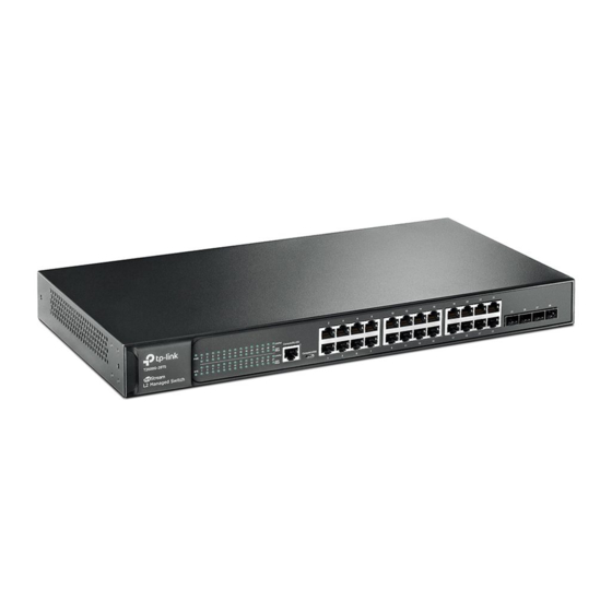
1.1 Product Overview T2600G-28TS and T2600G-52TS are Gigabit Ethernet switching products recently developed by TP-LINK. T2600G-28TS possesses 24 RJ45 ports and 4 SFP slots, while T2600G-52TS characterizes with 48 RJ45 ports and 4 SFP slots. The SFP slot enables remote connection with SFP slots on other devices through SFP module and fiber. - Page 8 1000Mbps. Each 10/100/1000Mbps RJ45 port has a corresponding 1000Mbps LED and Link/Act LED. SFP Port Designed to install the SFP module. T2600G-28TS features 4 individual SFP ports and supports 1000M SFP module connection only. The front panel of T2600G-52TS is shown as the following figure.
-
Page 9: Rear Panel
SFP Port Console Port T2600G-28TS T2600G-52TS Rear Panel ■ Due to the similarity of T2600G-28TS and T2600G-52TS in the rear panel, here T2600G-28TS is used as an example. 100-240V~50/60Hz 0.5A Power Socket Grounding Terminal Kensington Security Slot Figure 1-3 Rear Panel of T2600G-28TS... - Page 10 Gigabit L2 Managed Switch Kensington Security Slot Secure the lock (not provided) into the security slot to prevent the device from being stolen. Grounding Terminal The switch already comes with lightning protection mechanism. You can also ground the switch through the PE (Protecting Earth) cable of AC cord or with Ground Cable. For detailed information, please refer to Chapter 3 Lightning Protection.
-
Page 11: Chapter 2 Installation
Gigabit L2 Managed Switch Chapter 2 Installation 2.1 Package Contents Make sure that the package contains the following items. If any of the listed items is damaged or missing, please contact your distributor. One Switch One Power Cord, One Console Installation Guide Cable and One USB Cable T2600-... - Page 12 Gigabit L2 Managed Switch Please keep a proper temperature and humidity in the equipment room. Too high/low humidity may lead to bad insulation, electricity leakage, mechanical property changes and corrosions. Too high temperature may accelerate aging of the insulation materials and can thus significantly shorten the service life of the device.
-
Page 13: Installation Tools
Gigabit L2 Managed Switch instant current is strong enough to damage electronic devices, more effective lightning protection measures should be taken. Ensure the rack and device are well earthed. ■ Make sure the power socket has a good contact with the ground. ■... -
Page 14: Rack Installation
Gigabit L2 Managed Switch 3. Turnover the device and attach the supplied rubber feet to the recessed areas on the bottom at each corner of the device. Feet Bottom of the Device Notch Figure 2-1 Desktop Installation Rack Installation ■ To install the device in an EIA standard-sized, 19-inch rack, follow the instructions described below: 1. -
Page 15: Chapter 3 Lightning Protection
Gigabit L2 Managed Switch Chapter 3 Lightning Protection 3.1 Cabling Reasonably In the actual network environment, you may need cable outdoors and indoors, and the requirements for cabling outdoors and indoors are different. A reasonable cabling system can decrease the damage of induced lightning to devices. Note: It’s not recommended using Ethernet cables outdoors. - Page 16 Gigabit L2 Managed Switch Requirements for the distance between Ethernet cable and other pipelines are shown ■ in the table. Ethernet Cable Other Pipelines Min Parallel Net Length Min Parallel-overlapping Net Height L (mm) H (mm) Down-conductor 1000 Service pipe Compressed air pipe Thermal pipe (not wrapped) 500 Thermal pipe (wrapped)
-
Page 17: Connect To Ground
Gigabit L2 Managed Switch 3.2 Connect to Ground Connecting the device to ground is to quickly release the lightning over-voltage and over-current of the device, which is also a necessary measure to protect the body from electric shock. In different environments, the device may be grounded differently. The following will instruct you to connect the device to the ground in two ways, connecting to the grounding bar or connecting to the ground via the power cord. -
Page 18: Equipotential Bonding
Gigabit L2 Managed Switch Note: The figure is to illustrate the application and principle. The power cord you get from ■ the package and the socket in your situation will comply with the regulation in your country, so they may differ from the figure above. If you intend to connect the device to the ground via the PE (Protecting Earth) cable ■... -
Page 19: Use Lightning Arrester
Gigabit L2 Managed Switch 3.4 Use Lightning Arrester Power lightning arrester and signal lightning arrester are used for lighting protection. Power lightning arrester is used for limiting the voltage surge due to a lightning. If an outdoor AC power cord should be directly connected to the device, please use a power lightning arrester. -
Page 20: Chapter 4 Connection
Gigabit L2 Managed Switch Chapter 4 Connection 4.1 Ethernet Port Connect the Ethernet ports of the switch to the network devices by RJ45 cable as the following figure shows. RJ45 Port RJ45 Cable T260 0-28 Figure 4-1 Connecting the RJ45 Port 4.2 SFP Port Figure 4-2 demonstrates the connection of SFP port to an SFP module. -
Page 21: Console Port
Figure 4-3 SFP module The following table shows the detailed information of two SFP modules (TL-SM311LS and TL-SM311LM) produced by TP-LINK, which makes you have a round idea about it so as to give you a reference for choosing the suitable SFP module. -
Page 22: Verify Installation
Gigabit L2 Managed Switch Console(RJ45) T2600- 28TS Figure 4-4 Connecting the Console (RJ-45) Port Connect the Console (USB) port of the device with your computer by the USB cable as the following figure shows. Console(USB) T2600 -28TS Figure 4-5 Connecting the Console (USB) Port You can also manage the device through the console port, for details please refer to the CLI Reference Guide on the resource CD. -
Page 23: Power On
Gigabit L2 Managed Switch 4.5 Power On Plug the female connector of the provided power cord into the power socket of the device, and the male connector into a power outlet as the following figure shows. 100 -24 0V~ 50/6 0Hz 0.5A Figure 4-6 Connecting to Power Supply Note: The figure is to illustrate the application and principle. -
Page 24: Chapter 5 Configuration
Gigabit L2 Managed Switch Chapter 5 Confi guration 5.1 Confi gure the Switch via GUI 1. To access the GUI of the switch, open a web browser and type the default management address http://192.168.0.1 in the address field of the browser, then press the Enter key. -
Page 25: Configure The Switch Using Cli
The Micro-USB connector takes precedence over the RJ-45 connector. Install the TP-LINK USB Console Driver if you are using the USB serial port for the first time on a Windows-based PC. The driver can be found on the attached CD and Download page of our official website. - Page 26 Gigabit L2 Managed Switch Logon by Telnet ■ To log on to the switch by a Telnet connection, please take the following steps: 1. Firstly CLI commands about configuring Telnet login mode and login authentication information should be configured through Console connection. For more details please refer to the CLI Reference Guide on the resource CD.
-
Page 27: Appendix A Troubleshooting
Gigabit L2 Managed Switch Appendix A Troubleshooting What could I do if I forgot the username and password of the switch? 1. Connect the console port of the PC to the console port of the switch and open a terminal emulation program. - Page 28 Gigabit L2 Managed Switch Why does the terminal emulation program display abnormally? Please check as follows: 1. Make sure the power supply is normal and the console cable is properly connected. 2. Check if the console cable is the right type. 3.
-
Page 29: Appendix B Hardware Specifications
1000Base-T: 4-pair UTP (≤100m) of Cat. 5e, and Cat. 6 or Transmission Medium above 1000Base-X: MMF or SMF SFP Module (Optional) LEDs T2600G-28TS: PWR, SYS, 1000Mbps, Link/Act T2600G-52TS: PWR, SYS, 10/100/1000Mbps (Port 1-48), Link/Act (Port 49-52) Operating Temperature 0℃~40℃ Storage Temperature -40℃~70℃... - Page 32 Website: http://www.tp-link.com Tel: +86 755 26504400 E-mail: support@tp-link.com 7106506011 REV1.0.1...
Need help?
Do you have a question about the T2600G-28TS and is the answer not in the manual?
Questions and answers