Pro-Form endurance 720 e User Manual
Hide thumbs
Also See for endurance 720 e:
- User manual (36 pages) ,
- User manual (36 pages) ,
- User manual (36 pages)
Table of Contents
Advertisement
www.proform.com
USER'S MANUAL
Model No. PFEL57914.4
Serial No.
Write the serial number in the space
above for reference.
Serial Number
Decal
ACTIVATE YOUR
WARRANTY
To register your product and
activate your warranty today,
go to www.proformservice.com/
registration.
CUSTOMER CARE
For service at any time, go to
www.proformservice.com.
Or call 1-888-533-1333
Mon.–Fri. 6 a.m.–6 p.m. MT
Sat. 8 a.m.–12 p.m. MT
Please do not contact the store.
CAUTION
Read all precautions and
instructions in this manual before
using this equipment. Keep this
manual for future reference.
Advertisement
Table of Contents

Related Manuals for Pro-Form endurance 720 e


Summary of Contents for Pro-Form endurance 720 e
- Page 1 www.proform.com USER’S MANUAL Model No. PFEL57914.4 Serial No. Write the serial number in the space above for reference. Serial Number Decal ACTIVATE YOUR WARRANTY To register your product and activate your warranty today, go to www.proformservice.com/ registration. CUSTOMER CARE For service at any time, go to www.proformservice.com.
-
Page 2: Table Of Contents
TABLE OF CONTENTS WARNING DECAL PLACEMENT ............. . .2 IMPORTANT PRECAUTIONS . -
Page 3: Important Precautions
IMPORTANT PRECAUTIONS WARNING: To reduce the risk of burns, fire, electric shock, or injury to persons, read all important precautions and instructions in this manual and all warnings on your elliptical before using your elliptical. ICON assumes no responsibility for personal injury or property damage sus- tained by or through the use of this product. - Page 4 18. The elliptical does not have a freewheel; the 20. Over exercising may result in serious injury pedals will continue to move until the fly- or death. If you feel faint, if you become short wheel stops. Reduce your pedaling speed in of breath, or if you experience pain while a controlled way.
- Page 6 STANDARD SERVICE PLANS...
-
Page 7: Before You Begin
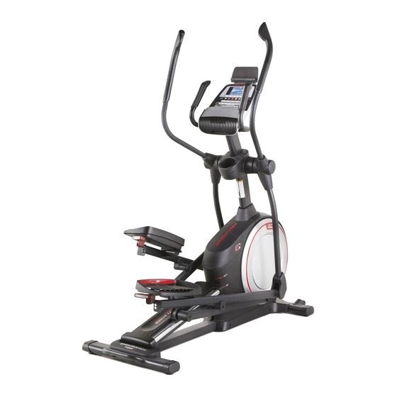
Thank you for selecting the revolutionary PROFORM reading this manual, please see the front cover of this ® ENDURANCE 720 E elliptical. The ENDURANCE 720 manual. To help us assist you, note the product model E elliptical provides an impressive selection of features number and serial number before contacting us. -
Page 8: Part Identification Chart
PART IDENTIFICATION CHART Use the drawings below to identify the small parts needed for assembly. The number in parentheses below each drawing is the key number of the part, from the PART LIST near the end of this manual. The number following the key number is the quantity needed for assembly. -
Page 9: Assembly
ASSEMBLY • To hire an authorized service technician to • To identify small parts, see page 8. assemble this product, call 1-800-445-2480. • In addition to the included tool(s), assembly • Assembly requires two persons. requires the following tools: one Phillips screwdriver •... - Page 10 3. Press the Cover Mounts (106) on the underside of the Rear Stabilizer Cover (15) into the Rear Stabilizer (2). 4. With the help of a second person, place some of the packing materials (not shown) under the front of the Frame (1). Have the second per- son hold the Frame to prevent it from tipping while you complete this step.
- Page 11 5. Orient the Upright (4) as shown. Have a second person hold the Upright near the Frame (1). Wire See the inset drawing. Locate the wire tie in the lower end of the Upright (4). Tie the wire tie to the Main Wire (110).
- Page 12 7. Using a plastic bag to keep your fingers clean, apply some of the included grease to the Pivot Axle (35) and to two 16mm Wave Washers (54). Insert the Pivot Axle (35) through the Upright (4) and center it. Tip: It may be helpful to use a rubber mallet.
- Page 13 9. Untie and discard the wire tie on the Main Wire (110). While a second person holds the Console (7) near the Upright (4), connect the wires on the Console to the Main Wire (110) and to the Sensor Wires (63). Insert the excess wire into the Upright (4).
- Page 14 11. Orient the Right Pedal Arm (58) as shown. Apply grease to the axle on the Right Pedal Arm (58). Attach the Right Pedal Arm (58) to the Right Roller Arm (59) with an M8 x 14mm Shoulder Screw (126), a Small Axle Cover (55), and an M8 Washer (97).
- Page 15 13. Orient the Rear Upright Cover (81) as shown. Attach the Rear Upright Cover (81) to the Upright (4) with four M4 x 16mm Screws (101); start all the Screws, and then tighten them. Orient the Front Upright Cover (117) as shown. Attach the Front Upright Cover (117) around the Upright (4) by pressing it onto the Rear Upright Cover (81).
- Page 16 15. Identify the Right Leg Inner Cover (83) and ori- ent it as shown. Attach the Right Leg Inner Cover (83) to the Right Upper Body Leg (60) with an M4 x 16mm Screw (101) and an M5 Washer (94). Next, identify the Right Upper Leg Outer Cover (69) and orient it as shown.
- Page 17 17. Orient the Rear Console Cover (80) as shown. Attach the Rear Console Cover (80) to the Upright (4) with two M4 x 16mm Screws (101). Next, orient the Front Console Cover (79) as shown. Attach the Front Console Cover (79) around the Upright (4) by pressing it onto the Rear Console Cover (80).
-
Page 18: How To Use The Elliptical
HOW TO USE THE ELLIPTICAL HOW TO PLUG IN THE POWER CORD A temporary adapter may 2-pole Receptacle This product must be grounded. If it should mal- be used to function or break down, grounding provides a path of connect the Adapter least resistance for electric current to reduce the risk power cord... - Page 19 HOW TO MOVE THE ELLIPTICAL HOW TO LEVEL THE ELLIPTICAL Due to the size and weight of the elliptical, moving If the elliptical it requires two persons. Stand in front of the elliptical, rocks slightly hold the upright, and place one foot against one of the on your floor wheels.
- Page 20 HOW TO ADJUST THE POSITIONS OF THE PEDALS Upper Each pedal can be adjusted to several positions. To Body Arms adjust each pedal, simply pull the pedal handle out- ward, move the pedal to the desired position, and then release the pedal handle into an adjustment hole beneath the pedal.
- Page 21 CONSOLE DIAGRAM MAKE YOUR FITNESS GOALS A REALITY WITH Upload your workout results to the iFit cloud IFIT.COM and track your accomplishments. With your new iFit-compatible fitness equipment, you can use an array of features on iFit.com to make your Set calorie, time, or distance goals for your fitness goals a reality: workouts.
- Page 22 FEATURES OF THE CONSOLE Note: If there is a sheet of plastic on the display, remove the plastic. The advanced console offers an array of features designed to make your workouts more effective and Note: The console can display speed and distance in enjoyable.
- Page 23 HOW TO USE THE MANUAL MODE 1. Begin pedaling or press any button on the console to turn on the console. See HOW TO TURN ON THE POWER on page 22. 2. Select the manual mode. Press the Manual button or the Home button to select the manual mode.
- Page 24 The matrix offers several display tabs. Press the Change the volume level of the Display button repeatedly until the desired tab console by pressing the volume is shown. You can also press the increase and increase and decrease buttons. decrease buttons next to the Enter button. 5.
- Page 25 6. Turn on the fan if desired. The display will also show the maximum pedaling speed (rpm), the maximum resistance level, and The fan has several speed the maximum incline level. settings. Press the fan increase 3. Start the workout. and decrease buttons repeat- edly to select a fan speed or to turn off the fan.
- Page 26 As you exercise, you will be prompted to keep your To stop the workout at any time, press the Pause/ pedaling speed near the target rpm for the cur- End button or stop pedaling. The time will flash in rent segment. When an upward-pointing arrow the display.
- Page 27 HOW TO USE A SET-A-GOAL WORKOUT Note: The calorie goal is an estimate of the number of calories that you will burn during 1. Begin pedaling or press any button on the the workout. The actual number of calories that console to turn on the console.
- Page 28 HOW TO USE AN IFIT WORKOUT 2. Begin pedaling or press any button on the console to turn on the console. You must have an iFit module to use an iFit workout. To purchase an iFit module at any time, go to When you turn on the console, the display will turn www.iFit.com or call the telephone number on the on.
- Page 29 5. Start the workout. HOW TO USE THE SOUND SYSTEM See step 3 on page 25. To play music or audio books through the console sound system while you exercise, plug a 3.5 mm male During some workouts, an audio coach will guide to 3.5 mm male audio cable (not included) into the you through your workout.
- Page 30 HOW TO CHANGE CONSOLE SETTINGS To view distance in miles, select ENGLISH. To view distance in kilometers, select METRIC. 1. Select the settings mode. Demo—The console features a display demo To select the settings mode, press the gear button. mode, designed to be used if the elliptical is dis- The settings information will appear in the display.
-
Page 31: Fcc Information
FCC INFORMATION This equipment has been tested and found to comply with the limits for a Class B digital device, pursuant to part 15 of the FCC Rules. These limits are designed to provide reasonable protection against harmful interference in a residential installation. This equipment generates, uses, and can radiate radio frequency energy and, if not installed and used in accordance with the instructions, may cause harmful interference to radio communications. -
Page 32: Maintenance And Troubleshooting
MAINTENANCE AND TROUBLESHOOTING MAINTENANCE HOW TO ADJUST THE REED SWITCH Regular maintenance is important for optimal If the console does not display correct feedback, the performance and to reduce wear. Inspect and properly reed switch should be adjusted. To adjust the reed switch, first press the power switch to the off posi- tighten all parts each time the elliptical is used. - Page 33 See the lower drawing on page 32. Plug in the See EXPLODED DRAWING C on page 39. power cord, press the power switch to the reset posi- Identify the Left and Right Shields (73, 74). Remove tion, and rock the Pulley (19) forward and backward the M4 x 19mm Screws (5), the M4 x 25mm Screws just enough that the Magnet (43) passes the Reed (138), and the M4 x 48mm Screw (107) from the Left...
-
Page 34: Exercise Guidelines
EXERCISE GUIDELINES Burning Fat—To burn fat effectively, you must exer- WARNING: cise at a low intensity level for a sustained period of Before beginning this time. During the first few minutes of exercise, your or any exercise program, consult your physi- body uses carbohydrate calories for energy. -
Page 35: Part List
PART LIST Model No. PFEL57914.4 R0416A Key No. Qty. Description Key No. Qty. Description Frame Roller Rear Stabilizer Right Pedal Ramp Large Axle Cover Upright 16mm Wave Washer M4 x 19mm Screw Small Axle Cover Front Stabilizer Roller Arm Bushing Console Large Arm Bearing Roller Guide... - Page 36 Key No. Qty. Description Key No. Qty. Description M4 x 16mm Screw Clevis Pin M8 Locknut Plastic Spacer M6 x 12mm Screw M4 x 19mm Self-tapping Screw M10 x 122mm Screw Bumper M10 Split Washer M8 x 14mm Shoulder Screw Cover Mount Tablet Holder M4 x 48mm Screw...
-
Page 37: Exploded Drawing
EXPLODED DRAWING A Model No. PFEL57914.4 R0416A... - Page 38 EXPLODED DRAWING B Model No. PFEL57914.4 R0416A...
- Page 39 EXPLODED DRAWING C Model No. PFEL57914.4 R0416A...
- Page 40 ORDERING REPLACEMENT PARTS To order replacement parts, please see the front cover of this manual. To help us assist you, be prepared to provide the following information when contacting us: • the model number and serial number of the product (see the front cover of this manual) •...
Need help?
Do you have a question about the endurance 720 e and is the answer not in the manual?
Questions and answers