Table of Contents
Advertisement
www.proform.com
Model No. PFEL09915.2
Serial No.
Write the serial number in the space
above for reference.
ACTIVATE YOUR
WARRANTY
To register your product and
activate your warranty today,
go to www.proformservice.com/
registration.
CUSTOMER CARE
For service at any time, go to
www.proformservice.com.
Or call 1-888-533-1333
Mon.–Fri. 6 a.m.–6 p.m. MT
Sat. 8 a.m.–12 p.m. MT
Please do not contact the store.
CAUTION
Read all precautions and
instructions in this manual before
using this equipment. Keep this
manual for future reference.
Serial
Number
Decal
USER'S MANUAL
Advertisement
Table of Contents

Related Manuals for Pro-Form CARDIO HIIT PFEL09915.2


Summary of Contents for Pro-Form CARDIO HIIT PFEL09915.2
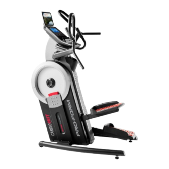
- Page 1 www.proform.com USER’S MANUAL Model No. PFEL09915.2 Serial No. Write the serial number in the space above for reference. Serial Number Decal ACTIVATE YOUR WARRANTY To register your product and activate your warranty today, go to www.proformservice.com/ registration. CUSTOMER CARE For service at any time, go to www.proformservice.com.
-
Page 2: Table Of Contents
TABLE OF CONTENTS WARNING DECAL PLACEMENT ............. . .2 IMPORTANT PRECAUTIONS . -
Page 3: Important Precautions
IMPORTANT PRECAUTIONS WARNING: To reduce the risk of serious injury, read all important precautions and instructions in this manual and all warnings on the trainer before using the trainer. ICON assumes no responsibility for personal injury or property damage sustained by or through the use of this product. - Page 4 STANDARD SERVICE PLANS...
-
Page 5: Before You Begin
BEFORE YOU BEGIN Thank you for selecting the revolutionary PROFORM reading this manual, please see the front cover of this ® CARDIO HIIT TRAINER. The CARDIO HIIT TRAINER manual. To help us assist you, note the product model trainer provides an impressive selection of features number and serial number before contacting us. -
Page 6: Part Identification Chart
PART IDENTIFICATION CHART Use the drawings below to identify the small parts needed for assembly. The number in parentheses below each drawing is the key number of the part, from the PART LIST near the end of this manual. The number following the key number is the quantity needed for assembly. -
Page 7: Assembly
ASSEMBLY • To hire an authorized service technician to • To identify small parts, see page 6. assemble this product, call 1-800-445-2480. • In addition to the included tool(s), assembly • Assembly requires two persons. requires the following tools: one Phillips screwdriver •... - Page 8 2. Identify the Right and Left Stabilizers (8, 9) and orient them as shown. Have a second person hold the Frame (1) and tip it to the left. IMPORTANT: Be careful not to damage the Shields (50, 51). Attach the Right Stabilizer (8) to the Frame (1) with four M10 x 20mm Screws (110);...
- Page 9 4. Attach the Right Pedal Base (2) to the Right Pedal Leg (24) with four M8 x 20mm Screws (102); start all the Screws, and then tighten them. Attach the Left Pedal Base (not shown) to the Left Pedal Leg (not shown) in the same way. 5.
- Page 10 6. See the upper drawing. With the help of a sec- ond person, orient the Console (5), the Console Cover (7), and the Console Bracket (4) as shown. Then, route the wires (A) on the Console through the Console Cover and the Console Bracket.
- Page 11 8. While a second person holds the Console Bracket (4) near the Frame (1), connect the wires on the Console to the Main Wire (115) and to the Pulse Wire (117). Avoid pinching the wires Tip: Avoid pinching the wires. Attach the Console Bracket (4) to the Frame (1) with two M8 x 86mm Screws (109) and two M8 x 15mm Screws (96);...
- Page 12 10. Identify the Rear and Front Pivot Covers (65, 66). Press a set of Rear and Front Pivot Covers (65, 66) together around the Right Handlebar (10) near the bend (A). Then, attach them to each other with two M4 x 22mm Screws (107). See the inset drawing.
- Page 13 12. Plug the Power Adapter (118) into the receptacle on the frame of the trainer. Note: To plug the Power Adapter (118) into an outlet, see HOW TO PLUG IN THE POWER ADAPTER on page 14. 13. Make sure that all parts are properly tightened before you use the trainer. Extra parts may be included. Place a mat beneath the trainer to protect the floor.
-
Page 14: How To Use The Trainer
HOW TO USE THE TRAINER HOW TO PLUG IN THE POWER ADAPTER HOW TO MOVE THE TRAINER IMPORTANT: If the trainer has been exposed to Due to the size and weight of the trainer, moving cold temperatures, allow it to warm to room tem- it requires two persons. - Page 15 HOW TO EXERCISE ON THE TRAINER HOW TO LEVEL THE TRAINER To mount the trainer, hold the handlebars or the pulse If the trainer grips and step onto the pedal that is in the lower posi- rocks slightly tion. Then, step onto the other pedal. Push the pedals on your floor until they begin to move with a continuous motion.
- Page 16 CONSOLE DIAGRAM FEATURES OF THE CONSOLE The advanced console offers an array of features designed to make your workouts more effective and enjoyable. When you use the manual mode, you can change the resistance of the pedals with the touch of a button. As you exercise, the console will provide continu- ous exercise feedback.
- Page 17 HOW TO USE THE MANUAL MODE Calories (Cals.)—When the manual mode is selected, this display mode will show the approxi- 1. Turn on the console. mate number of calories you have burned. When a workout is selected, this display mode will show Begin pedaling or press any button on the console either the approximate number of calories remain- to turn on the console.
- Page 18 My Trail—This tab will show a track that represents If there are 1/4 mile (400 m). As you exercise, the flashing sheets of plas- rectangle will show your progress. The My Trail tab tic on the metal contacts on the will also show the number of laps you complete.
- Page 19 HOW TO USE AN ONBOARD WORKOUT At the end of each segment of the workout, a series of tones will sound and the next segment of 1. Turn on the console. the profile will begin to flash. Begin pedaling or press any button on the console If a different resistance level is programmed for the to turn on the console.
- Page 20 4. Follow your progress with the display. THE OPTIONAL CHEST HEART RATE MONITOR See step 4 on page 17. Whether your goal is to 5. Measure your heart rate if desired. burn fat or to strengthen your See step 5 on page 18. cardiovascular system, the key 6.
- Page 21 HOW TO CONNECT YOUR SMART DEVICE TO THE HOW TO CONNECT YOUR HEART RATE MONITOR CONSOLE TO THE CONSOLE The console supports BLUETOOTH connections to The console is compatible with all BLUETOOTH Smart smart devices via the iFit app and to compatible heart heart rate monitors.
- Page 22 HOW TO CHANGE CONSOLE SETTINGS 3. Change settings as desired. 1. Select the settings mode. Units—The currently selected unit of measurement will appear in the display. To change the unit of To select the settings mode, press the gear button. measurement, press the Enter button repeatedly.
-
Page 23: Fcc Information
FCC INFORMATION This equipment has been tested and found to comply with the limits for a Class B digital device, pursuant to part 15 of the FCC Rules. These limits are designed to provide reasonable protection against harmful interference in a residential installation. This equipment generates, uses, and can radiate radio frequency energy and, if not installed and used in accordance with the instructions, may cause harmful interference to radio communications. -
Page 24: Maintenance And Troubleshooting
MAINTENANCE AND TROUBLESHOOTING MAINTENANCE HOW TO ADJUST THE REED SWITCH Regular maintenance is important for optimal If the console does not display correct feedback, the performance and to reduce wear. Inspect and properly reed switch should be adjusted. To adjust the reed switch, first unplug the power adapter. - Page 25 HOW TO ADJUST THE DRIVE BELT Then, locate the lower Adjustment If the pedals slip while you are pedaling, even while Screw (A). the resistance is adjusted to the highest level, the drive Tighten the lower belts may need to be adjusted. To adjust the drive Adjustment Screw belts, first unplug the power adapter.
-
Page 26: Exercise Guidelines
EXERCISE GUIDELINES Burning Fat—To burn fat effectively, you must exer- WARNING: cise at a low intensity level for a sustained period of Before beginning this time. During the first few minutes of exercise, your or any exercise program, consult your physi- body uses carbohydrate calories for energy. - Page 27 SUGGESTED STRETCHES The correct form for several basic stretches is shown at the right. Move slowly as you stretch; never bounce. 1. Toe Touch Stretch Stand with your knees bent slightly and slowly bend forward from your hips. Allow your back and shoulders to relax as you reach down toward your toes as far as possible.
-
Page 28: Part List
PART LIST Model No. PFEL09915.2 R0217A Key No. Qty. Description Key No. Qty. Description Frame Right Shield Right Pedal Base Front Cover Left Pedal Base Rear Cover Console Bracket Accessory Tray Base Console Stabilizer Cap Tablet Holder Foot Console Cover Wheel Right Stabilizer Right Wheel Cover... - Page 29 Key No. Qty. Description Key No. Qty. Description M4 x 16mm Flat Head Screw Reed Switch/Wire M8 x 20mm Screw Pulse Wire Cap Screw Power Adapter M6 x 110mm Screw Crank Cover Disc M8 x 25mm Screw Slant Cap M4 x 16mm Screw Pulley Magnet M4 x 22mm Screw Spring...
-
Page 30: Exploded Drawing
EXPLODED DRAWING A Model No. PFEL09915.2 R0217A... - Page 31 EXPLODED DRAWING B Model No. PFEL09915.2 R0217A...
-
Page 32: Ordering Replacement Parts
ORDERING REPLACEMENT PARTS To order replacement parts, please see the front cover of this manual. To help us assist you, be prepared to provide the following information when contacting us: • the model number and serial number of the product (see the front cover of this manual) •...
Need help?
Do you have a question about the CARDIO HIIT PFEL09915.2 and is the answer not in the manual?
Questions and answers