Advertisement
www.icon tness.com
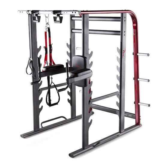
Model No. FMBE6912.0
Serial No.
Write the serial number in the space
above for reference.
Serial Number
QUESTIONS?
If you have questions, or if parts
are damaged or missing, DO NOT
CONTACT THE STORE; please
contact Customer Care.
IMPORTANT: Please register this
product (see the limited warranty
on the back cover of this manual)
before contacting Customer Care.
CALL TOLL-FREE:
1-800-999-3756
Mon.––Fri., 6 a.m.––6 p.m. MT
Sat. 8 a.m.––4 p.m. MT
ON THE WEB:
www.iconservice.com
CAUTION
Read all precautions and instruc-
tions in this manual before using
this equipment. Keep this manual
for future reference.
Decal
USER’'S MANUAL
Advertisement
Table of Contents

Subscribe to Our Youtube Channel
Related Manuals for Freemotion 620 BE


Summary of Contents for Freemotion 620 BE
- Page 1 www.icon tness.com Model No. FMBE6912.0 Serial No. USER’’S MANUAL Write the serial number in the space above for reference. Serial Number Decal QUESTIONS? If you have questions, or if parts are damaged or missing, DO NOT CONTACT THE STORE; please contact Customer Care.
-
Page 2: Table Of Contents
Apply the decal in the location shown. Note: The decal(s) may not be shown at actual size. FREEMOTION is a registered trademark of ICON IP, Inc. -
Page 3: Important Precautions
IMPORTANT PRECAUTIONS WARNING: To reduce the risk of serious injury, read all important precautions and instructions in this manual and all warnings on your weight rack before using your weight rack. ICON assumes no responsibility for personal injury or property damage sustained by or through the use of this product. -
Page 4: Before You Begin
® reading this manual, please see the back cover of this BE weight rack. The versatile 620 BE weight rack is manual. To help us assist you, note the product model designed to develop every major muscle group of the number and serial number before contacting us. -
Page 5: Part Identification Chart
PART IDENTIFICATION CHART Use the drawings below to identify the small parts needed for assembly. The number in parentheses below each drawing is the key number of the part, from the PART LIST near the end of this manual. The number following the key number is the quantity needed for assembly. -
Page 6: Assembly
ASSEMBLY •• To hire an authorized service technician to •• Left parts are marked ““L”” or ““Left”” and right parts assemble this product, call 1-800-445-2480. are marked ““R”” or ““Right.”” •• Assembly requires three persons. •• To identify small parts, see page 5. ••... - Page 7 2. Identify the Right Center Upright (5), and orient it as shown. Attach the Right Center Upright (5) to the Right Base (1) with two M10 x 75mm Hex Screws (39) and two M10 Washers (37); do not tighten the Screws yet.
- Page 8 4. Identify one of the two Top Frames (6), and ori- ent it as shown. Slide the Top Frame (6) onto the upper end of the Right Rear Frame (8). The Top Frame (6) should rest on the Right Front Upright (3) and the Right Center Upright (5).
- Page 9 6. Press three Rear Frame Caps (27) onto the Right Rear Frame (8). 7. If you plan to use Olympic weight plates (not included) with the weight rack, slide an Olympic Adapter (22) onto one of the storage posts on the Right Rear Frame (8).
- Page 10 8. Attach the Lower Crossbar (11) between the Right Rear Frame (8) and the Left Rear Frame (9) with four M10 x 130mm Screws (40); do not tighten the Screws yet. 9. Attach one of the two Upper Crossbars (14) between the two Center Uprights (5, 49) with four M10 x 80mm Screws (42);...
- Page 11 10. Orient the Pull-up Crossbar (7) and the two Carriages (15) as shown. Loosen and pull the Adjustment Knob (24) on one of the Carriages (15), and slide the Carriage onto the Pull-up Crossbar (7). Then, release the Adjustment Knob into one of the adjustment holes in the Pull-up Crossbar, and tighten the Adjustment Knob.
- Page 12 13. Attach an Armrest (16) to the Dip Arm (10) with four M6 x 20mm Screws (41). Start all four Screws, and then tighten them. Attach the other Armrest (16) in the same way. 14. Attach the Backrest (17) to the Dip Arm (10) with four M6 x 20mm Screws (41).
- Page 13 16. Set the two Spotters (18) on the Uprights (3, 4, 5, and 49) as shown. Make sure that both Spotters are at the same height. 17. Make sure that all parts are properly tightened before the weight rack is used. Note: Extra parts may be included.
-
Page 14: Adjustment
ADJUSTMENT The steps below explain how the weight rack can be adjusted. Make sure that all parts are properly tightened each time the weight rack is used. Replace any worn parts immediately. The weight rack can be cleaned with a damp cloth and a mild, non-abrasive detergent;... -
Page 15: Exercise Guidelines
EXERCISE GUIDELINES FOUR TYPES OF STRENGTH WORKOUTS to determine the appropriate length of time for each workout, and the numbers of repetitions and sets to Note: A ““repetition”” is one complete cycle of an complete. Progress at your own pace and be sensitive exercise, such as one sit-up. - Page 16 EXERCISE LOG Make copies of this page, and use the copies to schedule and record your strength and aerobic workouts. Scheduling and recording your workouts will help you to make exercise a regular and enjoyable part of your life. Strength Exercise Lbs.
- Page 17 NOTES...
-
Page 18: Part List
PART LIST Model No. FMBE6912.0 R0912A Key No. Qty. Description Key No. Qty. Description Right Base Short Foam Grip Left Base Rear Frame Cap Right Front Upright Adapter Cap Left Front Upright Frame Spacer Right Center Upright 50mm Round Cap Top Frame 32mm Round Cap Pull-up Crossbar... -
Page 19: Exploded Drawing
EXPLODED DRAWING Model No. FMBE6912.0 R0912A... -
Page 20: Ordering Replacement Parts
ORDERING REPLACEMENT PARTS To order replacement parts, please see the front cover of this manual. To help us assist you, be prepared to provide the following information when contacting us: •• the model number and serial number of the product (see the front cover of this manual) ••...
Need help?
Do you have a question about the 620 BE and is the answer not in the manual?
Questions and answers