Table of Contents
Advertisement
CONTENTS
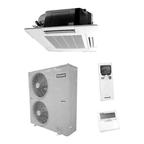
CS-W34BB4P CU-V34BBP5
CS-W34BB4P CU-W34BBP5
Page
3
4
10
11
12
14
26
© 2002 Matsushita Industrial Corporation Sdn. Bhd.
(11969-T). All rights reserved. Unauthorized copying
and distribution is a violation of law.
ORDER NO. MAC0208027C2
AIR CONDITIONER
Page
28
29
30
32
33
34
Advertisement
Table of Contents

Related Manuals for Panasonic CS-W34BB4P


Summary of Contents for Panasonic CS-W34BB4P
-
Page 1: Table Of Contents
ORDER NO. MAC0208027C2 AIR CONDITIONER CS-W34BB4P CU-V34BBP5 CS-W34BB4P CU-W34BBP5 CONTENTS Page Page 1 SERVICE INFORMATION 8 REFRIGERATION CYCLE 2 FEATURES 9 OPERATION RANGE 3 SPECIFICATION (HEAT PUMP TYPE ) 10 PIPE LENGTH 4 SPECIFICATION (COOLING ONLY TYPE ) 11 OPERATING CHARACTERISTIC... - Page 2 14 COMPONENT SPECIFICATION 23 TROUBLESHOOTING 15 CAPACITY AND POWER CONSUMPTION 24 EMERGENCY OPERATION 16 DISCHARGE AND SUCTION PRESSURE 25 CONTROL 17 SOUND DATA 26 WIRED REMOTE CONTROL INSTALLATION MANUAL 18 TWIN AND TRIPLE 27 WIRELESS REMOTE CONTROL INSTALLATION MANUAL 19 WIRING MISTAKE PREVENTION 28 INSTALLATION (INDOOR UNIT) 20 TEST OPERATION AND SELF DIAGNOSIS 29 INSTALLATION (OUTDOOR UNIT)
-
Page 3: Service Information
1 SERVICE INFORMATION Caution: Pb free solder has a higher melting point than standard solder; Typically the melting point is 50 - 70°F (30 - 40°C) higher. Please use a high temperature soldering iron. In case of the soldering iron with temperature control, please set it to 700 ± 20°F (370 ± 10°C). -
Page 4: Features
2 FEATURES The sound level is 45dB (A) for 34BB model during High 2.1. Variety of excellent features Fan speed and suitable for offices, shops, homes etc, when • • • • Compact design quiet operation is essential. • • • • Auto Swing Louvre Compact design 290 mm height, 840 mm width and 840 mm depth. -
Page 5: Product Features
2.2.1. Product features • • • • Low-noise design improves comfort in surrounding areas 1. The noise-suppressing winglet fan is a result of new research into vane design theory. The unique curved shape suppresses the generation of vortexes, thus reducing air flow noise. 2. -
Page 6: Wired Remote Control
2.4. A brand-new control method 2.5. Wired Remote Control using the latest in technology • • • • Easier power supply wiring connection Power supply wiring and other wiring tasks can be carried out more easily. − − − − Twin non-polar wires used to connect indoor and outdoor units. -
Page 7: Group Control Equipment
2.7. Group Control Equipment outdoor units, be sure to replace all refrigerant pipes 2.8. New refrigerant Series [R407C] also. pipe installation • • • • Check the pipe thickness. (1/4, 3/8, 1/2 : t = 0.8mm 5/8, 3/4 : t = 1.0mm) 2.8.1. - Page 8 • • • • The pressure after vacuum drawing should be 755 openings. mmHg or less. • • • • Use a special vacuum pump (with backflow-prevention mechanism). • • • • Gas must never be used for air purging. 13.
-
Page 10: Specification (Heat Pump Type )
3 SPECIFICATION (HEAT PUMP TYPE ) 3.1. CS-W34BB4P / CU-W34BBP5 ITEM / MODEL Indoor Unit Outdoor unit Main Body CS-W34BB4P CU-W34BBP5 Panel CZ-BT01P Remote CZ-RD51P (Wired) Control CZ-RL51P (Wireless) Cooling Capacity 10.0 BTU/h 34,100 Heating Capacity 11.2 BTU/h 38,200 Refrigerant Charge-less... -
Page 11: Specification (Cooling Only Type )
4 SPECIFICATION (COOLING ONLY TYPE ) 4.1. CS-W34BB4P / CU-V34BBP5 ITEM / MODEL Indoor Unit Outdoor unit Main Body CS-W34BB4P CU-V34BBP5 Panel CZ-BT01P Remote CZ-RD51P (Wired) Control CZ-RL01P (Wireless) Cooling Capacity 10.0 BTU/h 34,100 Refrigerant Charge-less Standard Air Volume for High Speed... -
Page 12: Technical Drawing
5 TECHNICAL DRAWING... -
Page 14: Circuit Diagram
6 CIRCUIT DIAGRAM... -
Page 26: Operating Instruction
7 OPERATING INSTRUCTION 7.1. Wired Remote Control (OPTIONAL PARTS) NOTES: • • • • Ensure that the correct button is pressed as simultaneous pressing of the multiple buttons will not make the setting correct. • • • • The illustration above is for explanatory purposes only. The appearance will be different during actual operation. •... - Page 27 7.2. Wireless Remote Control (OPTIONAL PARTS) NOTES: • • • • Ensure that the correct button is pressed as simultaneous pressing of the multiple buttons will not make the setting correct. • • • • The illustration above is for explanatory purpose only. The appearance will be different during actual operation. •...
-
Page 28: Refrigeration Cycle
8 REFRIGERATION CYCLE 8.1. Heating Model CS-W34BB4P / CU-W34BBP5 8.2. Cooling Only Model CS-W34BB4P / CU-V34BBP5... -
Page 29: Operation Range
9 OPERATION RANGE Power Supply The applicable voltage range for each unit is given in the following table. The working voltage among the three phases must be balanced within a 3% deviation from each voltage at the compressor terminals. The starting voltage must be higher than 85% of the rated voltage. -
Page 30: Pipe Length
10 PIPE LENGTH CORRECTION OF COOLING CAPACITY AND HEATING CAPACITIES Correction of cooling and heating capacities according to the connecting pipe length. The data of cooling capacities (marked on the name plate) are based on 5 meters connecting pipe and horizontal installation. For other pipe length of other installation multiply by the following correction factor to determine the revised cooling capacity. - Page 31 REFRIGERANT ADDITIONAL CHARGE 1. Piping installation by standard piping • • • • At the time of shipment from the factory, this unit is charged with enough refrigerant for an equivalent pipe length of 30m. (Refer to the following table) But when the piping length exceeds 30m, additional charge is required according to the following table.
-
Page 32: Operating Characteristic
IPT (kW) R.C. R.C. F.C. (A) IPT (kW) (Hz) COOL / HEAT COOL / HEAT (kW) (kW) COOL / HEAT COOL / HEAT CS-W34BB4P 4.67 / 4.97 3.55 / 3.74 0.62 0.13 0.91 0.20 6.20 / 6.50 3.88 / 4.07 CU-V34BBP5 4.63 / 4.93... -
Page 33: Fan Performance
12 FAN PERFORMANCE... -
Page 34: Safety Device
13 SAFETY DEVICE INDOOR UNIT Heat pump model Indoor unit CS-W34BB4P Cooling only model For Fan Motor Protection, °C Internal Protector (49F) °C For Control Protection, Fuse 3.15 OUTDOOR UNIT Outdoor Unit Heat pump model 50Hz CU-W34BBP5 Cooling only model... -
Page 35: Component Specification
11.39 Motor Starting Method Direct on-line Starting Type Rated Output Poles Insulation Class Type MMMAPOE Charge Evaporator Models CS-W34BB4P Tube Material Copper tube Outer Diameter Thickness 0.27 No. of Tubes/Row Fin Material Aluminium Thickness 0.105 Fin Pitch NO./inch Fin Surface... -
Page 36: Capacity And Power Consumption
15 CAPACITY AND POWER CONSUMPTION 15.1. HEATING PERFORMANCE Model Heating capacities are based on conditions below. CS-W34BB4P 1 phase, 50Hz, 230V Indoor temperature 20°C D.B.T. CU-W34BBP5 Outdoor temperature 7°C D.B. 6°C W.B.T. Heating capacity 11.2 kW Standard air volume 24m... -
Page 37: Cooling Performance
15.2. COOLING PERFORMANCE CS-W34BB4P Model Cooling capacities are based on conditions below. CS-W34BB4P 1 phase, 50Hz, 400V Indoor temperature 27°C D.B.T., 19°C W.B.T. Outdoor temperature 35°C D.B.T. Cooling capacity 10.0 kW Standard air volume 23m /min Cooling capacity Cooling power consumption Indoor Air Temp. -
Page 38: Discharge And Suction Pressure
16 DISCHARGE AND SUCTION PRESSURE 16.1. SATURATION TEMPERATURE OF DISCHARGE AND SUCTION PRESSURE Commonness TO ALL THE MODELS SATURATION TEMPERATURE OF DISCHARGE AND SUCTION PRESSURE * For intake temperature, consult the pressure - Enthalpy Table (R407C) at the end. -
Page 39: Sound Data
17 SOUND DATA... -
Page 41: Twin And Triple
18 TWIN AND TRIPLE • • • • Master unit and slave-units can be set automatically in twin 18.1. Twin and Triple Operation and triple systems. No address setting is necessary. • • • • Simultaneous air conditioning of wide spaces and corners is •... - Page 42 Turn on the power supply. 18.1.2. Automatic address setting for twin Operation: The unit will operate as slave unit 1. and triple systems Automatic address setting is not carried out at this time. Procedure: Turn on the power supply for the indoor and outdoor units.
-
Page 43: Piping Connections
• • • • The indoor units will not run for approximately 1 minute • • • • Do not turn off the power supply for at least 1 minute after while automatic twin/triple address resetting is being carried automatic twin/triple address resetting has been carried out. out. -
Page 44: Refrigerant Charging
18.3. Refrigerant charging • • • • For twin and triple-type systems The pipe length is the total of the branch pipe (L) and the junction pipes (la → lb → lc in order from the thickest diameter). At the point where the pipe length exceeds 30 m, determine the amount of refrigerant for the remaining liquid-side pipe diameters and pipe lengths from the following table in order to charge the system. - Page 45 18.4. Wiring...
-
Page 46: Wiring Mistake Prevention
19 WIRING MISTAKE PREVENTION Improved quality of installation work through adoption of an “Connection error prevention” circuit which prevents wiring mistakes Connection errors with the control wires and the power supply wires will not only contribute to burning-out of the control circuit board, but can also cause large-scale working losses and affect reliability. -
Page 47: Test Operation And Self Diagnosis
20 TEST OPERATION AND SELF DIAGNOSIS 20.1. Test operation 20.3. Test operation using the wired • • • • Always use a properly-insulated tool to operate the switch remote control on the circuit board. (Do not use your finger or any metallic object). - Page 48 20.4. Test operation using the wireless remote control <Air conditioner No.> − − − − The air conditioner No. “01” appears during normal installation and use. When using group control, a different number may appear. The air conditioner No. can be displayed by pressing the air conditioner No. button.
- Page 49 How to display the past error message An error code from 1F15 to 1F49 will be displayed. (The temperature setting display will also change to show the If the “CHECK” display on the wired remote control is not air conditioner No.) flashing, press the CHECK button continuously for 5 seconds or more to display the problem details for the last problem or the problem before that.
-
Page 51: Setting Of Save Energy And Thermistor Switch
21 SETTING OF SAVE ENERGY AND THERMISTOR SWITCH 21.1. Energy save setting 21.2. Switching to the remote • • • • Upper and lower limit can be set for the setting temperature control thermistor during cooling and heating operation. (The factory shipment •... -
Page 52: Group Control
22 GROUP CONTROL Setting group for 1 remote control unit be determined automatically after approximately 1 minute. • • • • When using a remote control thermostat, the thermostat (DIP switch settings are not necessary.) setting is used for all indoor units in the group. NOTE: •... -
Page 53: Troubleshooting
23 TROUBLESHOOTING If test operation does not proceed correctly section C) Symptom: Carry out test operation after approximately 12 hours have passed Remote control unit... Display of “No power supply” since the power was turned on (crankcase heater is energized). If operation is started by using the remote control within 1 minute of NOTE: turning on the power, the outdoor unit settings will not be made... - Page 54 1. The main power is turned on while the transmission connection cord is not connected (open circuit at section wires between the indoor unit(s) are not connected (open circuit at section A) Symptom: Symptom: − − − − Remote control unit.. . Display of “No power supply” Nothing abnormal appears on the remote control −...
- Page 55 1. The main power is turned on while the transmission unit No. 2 is possible. wires between the indoor unit and the outdoor unit are However, indoor unit No. 3 cannot be operated. not connected (open circuit at section A) Symptom: Operation of indoor unit No.
- Page 56 1. Automatic address setting (don’t need to set dip-switch) Reset the address by following the procedure: If the wiring is connected properly as above example, the a. After making sure that dip-switches No. 1 to 4 and No. address is set automatically by the main power supply. An 8 are OFF, stop the operation.
- Page 57 Procedures of deleting memory for twin/triple control system 1. Switch off the main power supply. 2. Set the No. 8 pin of dip switch (DSW1) at the indoor unit’s P.C. board to “ON” position. 3. Switch on the main power supply for a minute and then turn it off.
-
Page 58: Emergency Operation
24 EMERGENCY OPERATION Emergency operation Thermistor Cooling mode Heating mode • • • • Emergency operation of outdoor unit Indoor unit Room temperature Fixed at 25°C Pipe temperature Shorted Open Emergency operation can be carried out by setting the DSW1 switch on the printed circuit board of the outdoor Thermistor Cooling mode Heating mode unit to the EMERGENCY position. -
Page 59: Control
25 CONTROL Description of basic Functions 25.1. Cooling mode operation time chart (*1) Outdoor unit fan start control during cooling At the start of cooling mode and drying mode operation, the outdoor unit heat exchanger outlet temperature is detected in order to set the fan speed. -
Page 60: Drain Pump Control
25.2. Drain pump control 1. Basic operation During cooling mode, dry mode or defrost mode operation, the drain pump turns on when the compressor turns on. (The drain pump turns on during freezing prevention control.) • • • • When the compressor turns off, the drain pump will still continue its operation for 6 more minutes. •... - Page 61 (When float switch is continuously off) <If the float switch operates again after turning off> <If the float switch continues to be off> 25.3. Freezing prevention control 1. Operation During cooling mode operation, after 9 minutes have passed since the compressor turned on, the outdoor unit will stop its operation when the temperature detected by the indoor unit pipe temperature sensor is 2°C or lower.
- Page 62 25.4. Heating mode operation time chart (Heat pump type) (*2) Outdoor unit fan control during heating mode operation When the compressor is on during heating mode operation (except during defrosting and when the liquid bypass valve is on), the outdoor unit fan is controlled by means of input (CN2) indicating whether the contact of the heating pressure switch on the outdoor unit circuit board is open or closed.
- Page 63 25.5. Hot starting 1. When heating mode operation starts a. Start Hot start control commences when heating mode operation starts. b. Operation “PREHEAT” appears on the remote control display. (Other displays remain unchanged.) The indoor unit fan stops. In addition, during hot starting, the louvre stays at the horizontal position (angle 0°). c.
- Page 64 2. When defrosting is completed a. Start Hot start control commences when defrosting is completed. b. Operation “PREHEAT” appears on the remote control display. (Other displays remain unchanged) The indoor unit fan stops. In addition, during hot starting, the louvre stays at the horizontal position (angle 0°C). c.
- Page 65 25.7. Excess heat dissipation for indoor unit The indoor unit fan continue its operation for 30 seconds after heating mode operation turns off in order to dissipate excess heat. 1. When heating mode operation has stopped (LOW speed for 30 seconds) 2.
- Page 66 If P8 on the outdoor unit circuit board is shorted while the compressor is on during heating mode operation and the temperature detected by the outdoor unit heat exchanger outlet sensor is 25°C or lower, defrosting is carried out regardless of the current starting conditions.
- Page 67 3. Thermostat characteristics during automatic changeover operation a. Settings at the start of automatic changeover operation When operation changes from other modes to automatic changeover mode, operation starts at the temperature characteristics given in the table below. b. Thermostat characteristic when switching between cooling and heating mode operation Switching between cooling mode and heating mode operation is carried out as shown in the table below.
-
Page 68: Indoor Unit Fan Control
25.10. Indoor unit fan control 1. Fixing at LO, MED or HI When LO, MED or HI is set, the relay switches and operation is carried out at that setting. 2. Automatic fan speed When set to AUTO, the indoor unit fan operation changes as shown in the table below. (Indoor temperature) - (Setting temperature) (Units: K) Mode / Fan Speed Cooling... -
Page 69: Discharge Temperature Control
25.11. Forced operation during restart The compressor will not stop operating for 3 minutes after cooling mode operation starts, even if the indoor unit thermostat turns off. (However, the compressor will stop operating during this time if the indoor unit air intake temperature drops to 16°C and below during cooling mode operation.) 25.12. -
Page 70: Dip Switch Settings
25.15. Emergency operation When the emergency operation switch (DSW1) on the outdoor unit printed circuit board is set to emergency, the emergency operation is enabled. This allows normal operation to continue, with all abnormalities other than a discharge temperature abnormality, high pressure abnormality or overcurrent abnormality being ignored. 25.16. -
Page 71: Wired Remote Control Installation Manual
26 WIRED REMOTE CONTROL INSTALLATION MANUAL... -
Page 76: Wireless Remote Control Installation Manual
27 WIRELESS REMOTE CONTROL INSTALLATION MANUAL... -
Page 83: Installation (Indoor Unit)
28 INSTALLATION (INDOOR UNIT) -
Page 92: Installation (Outdoor Unit)
29 INSTALLATION (OUTDOOR UNIT) -
Page 103: Replacement Parts
30 REPLACEMENT PARTS 30.1. INDOOR UNIT... - Page 105 PART DESCRIPTION CS-W34BB4P BASE PAN ASS’Y CWD52K1034 INNER POLYSTYRENE (TOP) CWG071057 INNER POLYSTYRENE (SIDE) CWG07C1017 CABINET SIDE PLATE ASS’Y CWE04K1003 CABINET SIDE PLATE ASS’Y CWE04K1004 FAN MOTOR CWA921050 ANTI-VIBRATION BUSHING CWH501016 SCREW-FAN MOTOR CWH551032 CORD HOLDER CWD74K1001 TURBO FAN CWH03K1003...
- Page 107 PART DESCRIPTION PART NO. QTY. FRONT GRILLE CWE121026 COVER-AIR SWING MOTOR CWH811013 CONNECTOR-SHAFT CWH081002 CONNECTOR-SHAFT CWH081003 CONNECTOR-SHAFT CWH081004 BEARING CWH641006 VANE CWE241103 CONNECTOR-SHAFT CWH081005 CONNECTOR-SHAFT CWH081006 AIR SWING MOTOR CWA981065 INSULATION POLYSTYRENE CWG071105 INSULATION POLYSTYRENE CWG071106 INSULATION POLYSTYRENE CWG071107 WASHER CWH571025 COVER CWD932215...
- Page 108 30.2. OUTDOOR UNIT...
- Page 112 CU-W34BBP5 PART DESCRIPTION QTY. CU-W34BBP5 BASE PAN ASS’Y CWD52K1039A COMPRESSOR ANTI-VIBRATION BUSHING CWH501020 NUT FOR COMP. MOUNT. CWH4582065 CRANKCASE HEATER CWA341004 CONDENSER COMPLETE CWB32C1196 TUBE ASS’Y (CAPILLARY TUBE) CWT07K1075 PIPE HOLDER RUBBER CWG251016 CONDENSER SIDE PLATE CWD911123 CONDENSER TOP PLATE CWD911132 TUBE ASS’Y (PRESSURE SWITCH) CWT022605...
- Page 113 CU-V34BBP5 PART DESCRIPTION QTY. CU-V34BBP5 BASE PAN ASS’Y CWD52K1039A COMPRESSOR ANTI-VIBRATION BUSHING CWH501020 NUT FOR COMP. MOUNT. CWH4582065 CRANKCASE HEATER CWA341004 CONDENSER COMPLETE CWB32C1191 TUBE ASS’Y (CAPILLARY TUBE) CWT07K1079 PIPE HOLDER RUBBER CWG251016 PIPE HOLDER RUBBER CWG251015 CONDENSER SIDE PLATE CWD911123 CONDENSER TOP PLATE CWD911132...
Need help?
Do you have a question about the CS-W34BB4P and is the answer not in the manual?
Questions and answers