TP-Link TL-WR710N User Manual
Wifi pocket router/ap/tv adapter/repeater
Hide thumbs
Also See for TL-WR710N:
- Installation manual ,
- User manual (284 pages) ,
- Quick installation manual (2 pages)
Table of Contents
Advertisement
Quick Links
Advertisement
Table of Contents

Related Manuals for TP-Link TL-WR710N


Summary of Contents for TP-Link TL-WR710N
- Page 1 TL-WR710N WiFi Pocket Router/AP/TV Adapter/Repeater 1910011703 REV2.1.0...
- Page 2 Specifications are subject to change without notice. is a registered trademark of TP-LINK TECHNOLOGIES CO., LTD. Other brands and product names are trademarks or registered trademarks of their respective holders. No part of the specifications may be reproduced in any form or by any means or used to make any derivative such as translation, transformation, or adaptation without permission from TP-LINK TECHNOLOGIES CO., LTD.
-
Page 3: Ce Mark Warning
CE Mark Warning This is a class B product. In a domestic environment, this product may cause radio interference, in which case the user may be required to take adequate measures. RF Exposure Information This device meets the EU requirements (1999/5/EC Article 3.1a) on the limitation of exposure of the general public to electromagnetic fields by way of health protection. - Page 4 Indoor use only RECYCLING This product bears the selective sorting symbol for Waste electrical and electronic equipment (WEEE). This means that this product must be handled pursuant to European directive 2012/19/EU in order to be recycled or dismantled to minimize its impact on the environment.
-
Page 5: Declaration Of Conformity
TP-LINK TECHNOLOGIES CO., LTD DECLARATION OF CONFORMITY For the following equipment: Product Description: WiFi Pocket Router/AP/TV Adapter/Repeater Model No.: TL-WR710N Trademark: TP-LINK We declare under our own responsibility that the above products satisfy all the technical regulations applicable to the product within the scope of Council Directives:... -
Page 6: Table Of Contents
CONTENTS Package Contents .................... 错误!未定义书签。 Chapter 1. Introduction ......................2 Overview of the Router ....................2 Conventions.......................3 Main Features ......................3 Panel Layout ......................3 Chapter 2. Connecting the Router .....................5 System Requirements ....................5 Installation Environment Requirements ................5 Connecting the Router ....................5 2.3.1 Wireless Router Mode..................6 2.3.2 Access Point Mode ..................6 2.3.3... - Page 7 4.6.3 LAN ......................46 Wireless ........................47 4.7.1 Wireless Settings ..................47 4.7.2 Wireless Security ..................48 4.7.3 Wireless MAC Filtering .................. 51 4.7.4 Wireless Advanced ..................53 4.7.5 Wireless Statistics ..................54 DHCP ........................55 4.8.1 DHCP Settings ..................... 55 4.8.2 DHCP Client List...................
- Page 8 4.14 Advanced Routing ....................83 4.14.1 Static Routing List ..................83 4.14.2 System Routing Table ................... 84 4.15 Bandwidth Control ....................85 4.15.1 Control Settings .................... 85 4.15.2 Rule List....................... 86 4.16 IP & MAC Binding..................... 87 4.16.1 Binding Setting ..................... 87 4.16.2 ARP List.......................
- Page 9 5.7.1 Wireless Settings ..................109 5.7.2 Wireless Security ..................111 5.7.3 Wireless MAC Filtering ................114 5.7.4 Wireless Advanced ..................116 5.7.5 Wireless Statistics ..................117 DHCP ........................118 5.8.1 DHCP Settings ................... 118 5.8.2 DHCP Client List..................119 5.8.3 Address Reservation...................
- Page 10 6.6.4 Wireless Advanced ..................143 6.6.5 Wireless Statistics ..................144 DHCP ........................145 6.7.1 DHCP Settings ................... 145 6.7.2 DHCP Client List..................146 6.7.3 Address Reservation................... 147 USB Settings ......................148 6.8.1 Storage Sharing..................148 6.8.2 Media Server ....................150 6.8.3 User Accounts ....................
- Page 11 USB Settings ......................171 7.8.1 Storage Sharing..................171 7.8.2 Media Server ....................173 7.8.3 User Accounts .................... 175 System Tools ......................176 7.9.1 Diagnostic ....................176 7.9.2 Firmware Upgrade ..................178 7.9.3 Factory Defaults ..................179 7.9.4 Backup & Restore ..................179 7.9.5 Reboot .......................
- Page 12 8.8.1 Storage Sharing..................209 8.8.2 Media Server ....................210 8.8.3 User Accounts .................... 212 Forwarding......................214 8.9.1 Virtual Servers .................... 214 8.9.2 Port Triggering .................... 216 8.9.3 DMZ ......................218 8.9.4 UPnP ......................218 8.10 Security ......................... 219 8.10.1 Basic Security .................... 219 8.10.2 Advanced Security ..................
- Page 13 8.16.3 Dyndns org DDNS ..................243 8.17 System Tools ......................244 8.17.1 Time Settings ..................... 244 8.17.2 Diagnostic ....................245 8.17.3 Firmware Upgrade ..................246 8.17.4 Factory Defaults ..................247 8.17.5 Backup & Restore ..................248 8.17.6 Reboot ....................... 248 8.17.7 Password ....................
-
Page 14: Chapter 1. Introduction
Chapter 1. Introduction 1.1 Overview of the Router Small enough to fit in the average pocket, the router is uniquely suited to provide robust wireless networking to travelers, students, or anyone else for work or play. Incredible Speed ccessontroInstallation The router supports the newest 802.11n standards, and provides backward compatibility with older 802.11b/g standards as well. -
Page 15: Conventions
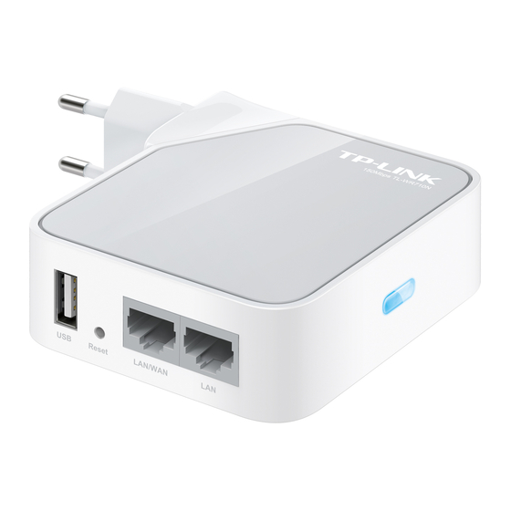
1.2 Conventions Parameters provided in the pictures are just references for setting up the product, which may differ from the actual situation. You can set the parameters according to your demand. 1.3 Main Features Portable design, ideal for travel and home use ... - Page 16 quick-flash from slow-flash. And then release the button and wait the Router to reboot to its factory default settings. LAN/WAN: This LAN/WAN port works as LAN in AP/Repeater/Client/WISP Client Router mode and as WAN in Wireless Router mode. As LAN, it connects the Router to the local PC; as WAN, it enables you connect the DSL/cable Modem, or Ethernet.
-
Page 17: Chapter 2. Connecting The Router
Chapter 2. Connecting the Router 2.1 System Requirements Each PC in the LAN needs a working Ethernet Adapter TCP/IP protocol must be installed on each PC Web browser, such as Microsoft Internet Explorer 5.0 or later, Mozilla Firefox, Apple Safari ... -
Page 18: Wireless Router Mode
2.3.1 Wireless Router Mode Create an instant private wireless network and share Internet to multiple Wi-Fi devices. This mode is suitable for hotel rooms and home networks. (Note: if the hotel’s Internet has an authentication process, you will need to authenticate only once and only on one device.) Connect the LAN/WAN port of the router to the LAN Port on the DSL/Cable Modem. -
Page 19: Repeater Mode
Plug the power plug of the router in electrical wall socket. Power on the PC(s) and notebook(s). 2.3.3 Repeater Mode Repeat signal from an existing wireless network. This mode is suitable to extend wireless coverage, reaching devices that were previously too far from your primary router to maintain a stable wireless connection. -
Page 20: Wisp Client Router Mode
Connect the PC to the LAN or LAN/WAN port of the router with an Ethernet cable. Plug the power plug of the router in electrical wall socket. Power on the PC(s). 2.3.5 WISP Client Router Mode Use as a client router to receive Internet access from a Wireless Internet Service Provider (WISP), and share that access with local devices. -
Page 21: Chapter 3. Quick Installation Guide
Chapter 3. Quick Installation Guide This chapter will show you how to configure the basic functions of your router using Quick Setup Wizard within minutes. 3.1 TCP/IP Configuration The default IP address is 192.168.0.254. And the default Subnet Mask is 255.255.255.0. These values can be changed as you desire. - Page 22 Enter the Security key. Click OK. 3) If you can see Connected after the default SSID, you’ve successfully connected to the wireless network. Note: The default SSID and Password of your Router are on the label. Both are case-sensitive. The pre-encryption function is enabled by default and the default Network key/Security key is the Password on the label.
- Page 23 If the result displayed is similar to the following figure, it means the connection between your PC and the Router has failed. Please check the connection following these steps: Is the connection between your PC and the Router correct? ...
-
Page 24: Quick Installation Guide
3.2 Quick Installation Guide With a Web-based utility, it is easy to configure and manage the router. The Web-based utility can be used on any Windows, Macintosh or UNIX OS with a Web browser, such as Microsoft Internet Explorer, Mozilla Firefox or Apple Safari. To access the configuration utility, open a web-browser and type in the default address http://tplinklogin.net in the address field of the browser. -
Page 25: Wireless Router Mode
Click Next, and then Working Mode page will appear. Note: The Router supports five working modes for multi-user to access the Internet: Wireless Router, Access Point, Repeater, Client and WISP Client Router. In Wireless Router mode, the device enables multiple users to share the Internet connection via ADSL/Cable Modem. In Access Point mode, this device can be connected to a wired network and transform the wired access into wireless that multiple devices can share together. - Page 26 The Router provides Auto-Detect function and supports five popular ways Dynamic IP, Static IP, PPPoE/Russia PPPoE, L2TP/Russia L2TP and PPTP/Russia PPTP to connect to the Internet. It’s recommended that you make use of the Auto-Detect function. If you are sure of what kind of connection type your ISP provides, you can select the very type and click Next to go on configuring.
- Page 27 User Name/Password - Enter the User Name and Password provided by your ISP. These fields are case sensitive. If you have difficulty with this process, please contact your ISP. Confirm Password - Re-enter the password provided by your ISP to ensure the ...
- Page 28 User Name/Password - Enter the User Name and Password provided by your ISP. These fields are case sensitive. If you have difficulty with this process, please contact your ISP. Dynamic IP/Static IP - Select Static IP if IP address, subnet mask, gateway and DNS ...
- Page 29 Wireless Radio - Enable or disable the wireless radio choosing from the pull-down list. Wireless Network Name - Enter a string of up to 32 characters. The same name of SSID (Service Set Identification) must be assigned to all wireless devices in your network.
-
Page 30: Access Point Mode
Please also note the key is case sensitive, this means that upper and lower case keys will affect the outcome. It would also be a good idea to write down the key and all related wireless security settings. No Change - If you chose this option, wireless security configuration will not change! ... - Page 31 Wireless Network Name - Enter a string of up to 32 characters. The same name of SSID (Service Set Identification) must be assigned to all wireless devices in your network. The default SSID is set to be TP-LINK_XXXXXX (XXXXXX indicates the last unique six numbers of each Router’s MAC address).
-
Page 32: Repeater Mode
Channel Width - Select any channel width from the pull-down list. The default setting is automatic, which can automatically adjust the channel width for your clients. Wireless Security Mode - This option should be chosen according to the security ... - Page 33 Wireless Name of Root AP - The SSID of AP that you want to access. MAC Address of Root AP - The MAC address of AP that you want to access. Survey - Click this button, you can search the AP which runs in the environment. ...
-
Page 34: Client Mode
Note: If you know the SSID of the desired AP, you can also input it into the field "SSID" manually. Click the Next button. You will then see the Finish page. Because something has changed on the Wireless Repeater page, you will see the Finish page. - Page 35 Wireless Name of Root AP - Enter the SSID that you want to access. MAC Address of Root AP - Enter the MAC address of AP that you want to access. Survey - Click this button, you can survey the AP which runs in the environment. ...
-
Page 36: Wisp Client Router Mode
Click the Next button. You will then see the Finish page. Click the Reboot button to make your wireless configuration take effect and finish the Quick Setup. 3.2.5 WISP Client Router Mode When you choose WISP Client Router on Working Mode page, take the following steps: Click Next, and then WAN Connection Type page will appear. - Page 37 Dynamic IP - Your ISP uses a DHCP service to assign your Router an IP address for connecting to the Internet. When the Router connects to a DHCP server, or the ISP supplies you with DHCP connection, please choose this type. If you choose this type of connection, no configuration should be set and you can go on with the wireless configuration.
- Page 38 SSID - The SSID of the AP your router is going to connect to as a client. You can also use the search function to select the SSID to join. BSSID - The BSSID of the AP your router is going to connect to as a client. You can also ...
- Page 39 Wireless Security Mode - You can configure the security settings of your wireless network. Wireless Password - Input the password of your Local SSID. Click Survey button on the Wireless page, and then AP List page will appear. Find the SSID of the Access Point you want to access, and click Connect in the corresponding row.
-
Page 40: Chapter 4. Configuration For Wireless Router Mode
Chapter 4. Configuration for Wireless Router Mode This chapter will show each Web page's key functions and the configuration way for Wireless Router Mode of the router. 4.1 Login After your successful login, you can configure and manage the device. There are main menus on the left of the web-based utility. - Page 41 Firmware Version - The version information of the Router’s firmware. Hardware Version - The version information of the Router’s hardware. LAN - This field displays the current settings or information for the LAN, you can configure them in the Network > LAN page. ...
- Page 42 Wireless - This field displays basic information or status for wireless function, you can configure them in the Wireless > Wireless Settings page. Working Mode - The current wireless working mode in use. Wireless Radio - Indicates whether the wireless radio feature of the AP is enabled or disabled.
-
Page 43: Quick Setup
4.3 Quick Setup Please refer to Section 3.2: "Quick Installation Guide." 4.4 WPS WPS (Wi-Fi Protected Setup) can help you to quickly and securely connect to a network. This section will guide you to add a new wireless device to an existing network quickly by function. The WPS function is only available when the Operation Mode is set to Access Point. - Page 44 For the configuration of the new device, here takes the Wireless Adapter of our company for example. By PBC If the wireless adapter supports Wi-Fi Protected Setup and the Push Button Configuration (PBC) method, you can add it to the network by PBC with the following two methods. Method One: Step 1: Keep the WPS Status as Enabled and click the Add Device button, then the following screen will appear.
- Page 45 The WPS Configuration Screen of Wireless Adapter Method Two: Enter the PIN into my AP For the configuration of the wireless adapter, please choose “Enter the PIN of this Step 1: device into my access point or wireless router” in the configuration utility of the WPS as below, and click Connect.
- Page 46 Method Three: Enter the PIN from my AP Step 1: Get the Current PIN code of the AP (each AP has its unique PIN code. Here takes the PIN code 12345670 of this AP for example). Step 2: For the configuration of the wireless adapter, please choose “Enter the PIN of my access point or wireless router”...
-
Page 47: Working Mode
Note: The WPS LED on the AP will light green for five minutes if the device has been successfully added to the network. The WPS function cannot be configured if the Wireless function of the AP is disabled. Please make sure the Wireless function is enabled before configuring the WPS. -
Page 48: Network
4.6 Network There are three submenus under the Network menu: WAN, MAC Clone and LAN. Click any of them, and you will be able to configure the corresponding function. 4.6.1 WAN Choose menu “Network → WAN”, and then you can configure the IP parameters of the WAN on the screen below. - Page 49 Use These DNS Servers - If your ISP gives you one or two DNS addresses, select Use These DNS Servers and enter the primary and secondary addresses into the correct fields. Otherwise, the DNS servers will be assigned dynamically from your ISP. ...
- Page 50 Click the Save button to save your settings. If your ISP provides a PPPoE connection, select PPPoE/Russia PPPoE option. Then you should enter the following parameters: User Name/Password - Enter the User Name and Password provided by your ISP. These fields are case-sensitive.
- Page 51 when you attempt to access the Internet again. If you want your Internet connection keeps active all the time, please enter “0” in the Max Idle Time field. Otherwise, enter the number of minutes you want to have elapsed before your Internet access disconnects.
- Page 52 MTU Size - The default MTU size is “1480” bytes, which is usually fine. It is not recommended that you change the default MTU Size unless required by your ISP. Service Name/AC Name - The service name and AC (Access Concentrator) name ...
- Page 53 User Name/Password - Enter the User Name and Password provided by your ISP. These fields are case-sensitive. Auth Server - Enter the authenticating server IP address or host name. Auth Domain - Type in the domain suffix server name based on your location, ...
- Page 54 Click the Connect button to connect immediately. Click the Disconnect button to disconnect immediately. Caution: Sometimes the connection cannot be terminated although you specify a time to Max Idle Time because some applications are visiting the Internet continually in the background.
- Page 55 the Internet again. If you wish to activate Connect on Demand, check the radio button. If you want your Internet connection to remain active at all times, enter 0 in the Max Idle Time field. Otherwise, enter the number of minutes you want to have elapsed before your Internet connection terminates.
- Page 56 User Name/Password - Enter the User Name and Password provided by your ISP. These fields are case-sensitive. Dynamic IP/ Static IP - Choose either as you are given by your ISP and enter the ISP’s IP address or the domain name. If you choose static IP and enter the domain name, you should also enter the DNS assigned by your ISP.
-
Page 57: Mac Clone
Connect Automatically - Connect automatically after the Router is disconnected. To use this option, check the radio button. Connect Manually - You can configure the Router to make it connect or disconnect manually. After a specified period of inactivity (Max Idle Time), the Router will disconnect from your Internet connection, and you will not be able to re-establish your connection automatically as soon as you attempt to access the Internet again. -
Page 58: Lan
2. If you change WAN MAC Address when the WAN connection is PPPoE, it will not take effect until the connection is re-established. 4.6.3 LAN Choose menu “Network → LAN”, and then you can configure the IP parameters of the LAN on the screen as below. -
Page 59: Wireless
4.7 Wireless There are five submenus under the Wireless menu: Wireless Settings, Wireless Security, Wireless MAC Filtering, Wireless Advanced and Wireless Statistics. Click any of them, and you will be able to configure the corresponding function. 4.7.1 Wireless Settings Choose menu “Wireless → Wireless Settings”, and then you can configure the basic settings for the wireless network on this page. -
Page 60: Wireless Security
Mode - Select the desired mode. The default setting is 11bgn mixed. 11bg mixed - Select if you are using both 802.11b and 802.11g wireless clients. 11bgn mixed - Select if you are using a mix of 802.11b, 11g, and 11n wireless clients. When 11bg mixed mode is selected, only 11bg mixed wireless stations can connect to the Router. - Page 61 There are three wireless security modes supported by the Router: WPA/WPA2-Personal, WPA/WPA2-Enterprise and WEP (Wired Equivalent Privacy). Disable Security - The wireless security function can be enabled or disabled. If disabled, the wireless stations will be able to connect the Router without encryption. But it’s strongly recommended to choose one of the following modes to enable security.
- Page 62 WPA /WPA2-Enterprise - It’s based on Radius Server. Version - you can choose the version of the WPA security from the pull-down list. The default setting is Automatic, which can select WPA (Wi-Fi Protected Access) or WPA2 (WPA version 2) automatically based on the wireless station's capability and request. ...
-
Page 63: Wireless Mac Filtering
Note: If you do not set the key, the wireless security function is still disabled even if you have selected Shared Key as Authentication Type. Be sure to click the Save button to save your settings on this page. 4.7.3 Wireless MAC Filtering Choose menu “Wireless →... - Page 64 Give a simple description for the wireless station in the Description field. For example: Wireless station A. Select Enabled or Disabled for this entry on the Status pull-down list. Click the Save button to save this entry. To modify or delete an existing entry: Click the Modify in the entry you want to modify.
-
Page 65: Wireless Advanced
4.7.4 Wireless Advanced Choose menu “Wireless → Wireless Advanced”, and then you can configure the advanced settings of your wireless network. Transmit Power - Here you can specify the transmit power of Router. You can select High, Middle or Low which you would like. High is the default setting and is recommended. ... -
Page 66: Wireless Statistics
specify the value between 1-255 Beacon Intervals. The default value is 1, which indicates the DTIM Interval is the same as Beacon Interval. Enable WMM - WMM function can guarantee the packets with high-priority messages being transmitted preferentially. It is strongly recommended enabled. ... -
Page 67: Dhcp
If the numbers of connected wireless stations go beyond one page, click the Next button to go to the next page and click the Previous button to return the previous page. Note: This page will be refreshed automatically every 5 seconds. 4.8 DHCP There are three submenus under the DHCP menu, DHCP Settings, DHCP Clients List and Address Reservation. -
Page 68: Dhcp Client List
Address Lease Time - The Address Lease Time is the amount of time a network user will be allowed connection to the Router with their current dynamic IP Address. Enter the amount of time in minutes and the user will be "leased" this dynamic IP Address. After the time is up, the user will be automatically assigned a new dynamic IP address. - Page 69 LAN, that PC will always receive the same IP address each time when it accesses the DHCP server. Reserved IP addresses should be assigned to the servers that require permanent IP settings. MAC Address - The MAC address of the PC for which you want to reserve an IP address. ...
-
Page 70: Usb Settings
4.9 USB Settings There are three submenus under the USB Settings menu, Storage Sharing, Media Server and User Accounts. Click any of them, and you will be able to configure the corresponding functions. 4.9.1 Storage Sharing Choose menu “USB Settings→Storage Sharing”, you can configure a USB disk drive attached to the router and view volume and share such properties as share name, capacity, used space, and free space on this page as shown below. -
Page 71: Media Server
Click the Eject Disk button to safely remove the USB storage device that is connected to USB port. This takes the drive offline. A message will appear on your web browser when it is safe to detach the USB disk. Click the Rescan button to start a new scan. - Page 72 Server Name - The name of this Media Server. Server Status - Indicates the Media Server’s current status, started or stopped. You can click the Start button to start the Media Server and click the Stop button to stop it. Name - The display name of this folder.
-
Page 73: User Accounts
Display Name - You can enter a display name for the share folder. Share entire partition - Choose this option and then the folders contained in this partition will all be shared. Folder Location- Displays the location of this folder. ... - Page 74 Only Administrator can use a Web browser to transfer the files from a PC to the Writable shared volume on the USB drive. To add a new user account, please follow the steps below: Click Add New User button. Self-define a User Name. Enter the password in the Password field.
-
Page 75: Forwarding
Note: Please restart the service for the new settings to take effect. If you cannot use the new user name and password to access the shares, press Windows logo + R to open the Run dialog box and type net use \\192.168.0.254 /delete /yes and press Enter. (192.168.0.254 is your router's LAN IP address. - Page 76 IP Address - The IP Address of the PC providing the service application. Protocol - The protocol used for this application, either TCP, UDP, or All (all protocols supported by the Router). Status - The status of this entry, either Enabled or Disabled. ...
-
Page 77: Port Triggering
Click the Next button to go to the next page and click the Previous button to return the previous page. Note: If you set the service port of the virtual server as 80, you must set the Web management port on “Security →... - Page 78 To add a new rule, follow the steps below: Click the Add New… button, the next screen will pop up. Select a common application from the Common Applications drop-down list, then the Trigger Port field and the Incoming Ports field will be automatically filled. If the Common Applications do not have the application you need, enter the Trigger Port and the Incoming Ports manually.
-
Page 79: Dmz
4.10.3 DMZ Choose menu “Forwarding → DMZ”, and then you can view and configure DMZ host. The DMZ host feature allows one local host to be exposed to the Internet for a special-purpose service such as Internet gaming or videoconferencing. DMZ host forwards all the ports at the same time. Any PC whose port is being forwarded must have its DHCP client function disabled and should have a new static IP Address assigned to it because its IP Address may be changed when using the DHCP function. -
Page 80: Security
App Description - The description provided by the application in the UPnP request. External Port - The external port the Router opens for the application. Protocol - The type of protocol the Router opens for the application. ... -
Page 81: Advanced Security
Firewall - A firewall protects your network from the outside world. Here you can enable or disable the Router’s firewall. SPI Firewall - SPI (Stateful Packet Inspection, also known as dynamic packet filtering) helps to prevent cyber attacks by tracking more state per session. It validates that the traffic passing through the session conforms to the protocol. - Page 82 Packets Statistics Interval (5~60) - The default value is 10. Select a value between 5 and 60 seconds from the drop-down list. The Packets Statistics Interval value indicates the time section of the packets statistics. The result of the statistics is used for analysis by SYN Flood, UDP Flood and ICMP-Flood.
-
Page 83: Local Management
Enable TCP-SYN-FLOOD Attack Filtering - Enable or Disable the TCP-SYN-FLOOD Attack Filtering. TCP-SYN-FLOOD Packets Threshold (5~3600) - The default value is 50. Enter a value between 5 ~ 3600. When the current TCP-SYN-FLOOD Packets numbers is beyond the set value, the Router will startup the blocking function immediately. -
Page 84: Remote Management
Click the Save button to save your settings. Note: If your PC is blocked but you want to access the Router again, press and hold the WPS button for more than 5 seconds to reset the Router to factory defaults. 4.11.4 Remote Management You can configure the Remote Management function on this page. - Page 85 Parental Control - Check Enable if you want this function to take effect, otherwise check Disable. MAC Address of Parental PC - In this field, enter the MAC address of the controlling PC, or you can make use of the Copy To Above button below. ...
- Page 86 Click the Enable All button to enable all the rules in the list. Click the Disable All button to disable all the rules in the list. Click the Delete All button to delete all the entries in the table. Click the Next button to go to the next page, or click the Previous button return to the previous page.
-
Page 87: Access Control
Enter “www.google.com” in the Allowed Domain Name field. Select “Schedule_1” you create just now from the Effective Time drop-down list. In Status field, select Enable. Click Save to complete the settings. Then you will go back to the Parental Control Settings page and see the following list. 4.13 Access Control There are four submenus under the Access Restriction menu: Rule, Host, Target and Schedule. - Page 88 Enable Internet Access Control - Select the check box to enable the Internet Access Restriction function, so the Default Filter Policy can take effect. Rule Name - Here displays the name of the rule and this name is unique. ...
- Page 89 For example: If you desire to allow the host with MAC address 00-11-22-33-44-AA to access www.google.com only from 18:00 to 20:00 on Saturday and Sunday, and forbid other hosts in the LAN to access the Internet, you should follow the settings below: Click “Access Control →...
-
Page 90: Host
4.13.2 Host Choose menu “Access Control → Host”, you can view and set a Host list. The host list is necessary for the Access Restriction Rule. Host Description - Here displays the description of the host and this description is unique. ... -
Page 91: Target
For example: If you desire to restrict the internet activities of host with MAC address 00-11-22-33-44-AA, you should first follow the settings below: Click Add New... button to enter the Add or Modify a Host Entry page. In Mode field, select MAC Address from the drop-down list. In Host Description field, create a unique description for the host (e.g. - Page 92 Target Description - Here displays the description about the target and this description is unique. Information - The target can be IP address, port, or domain name. Modify - To modify or delete an existing entry. To add a new entry, please follow the steps below. Click the Add New…...
-
Page 93: Schedule
For example: If you desire to restrict the internet activities of host with MAC address 00-11-22-33-44-AA in the LAN to access www.google.com only, you should first follow the settings below: Click Add New… button to enter the Add or Modify an Access Target Entry page. In Mode field, select Domain Name from the drop-down list. - Page 94 Schedule Description - Here displays the description of the schedule and this description is unique. Day - Here displays the day(s) in a week. Time - Here displays the time period in a day. Modify - Here you can edit or delete an existing schedule. To add a new schedule, follow the steps below.
-
Page 95: Advanced Routing
Click Add New... button to enter the Advanced Schedule Settings page. In Schedule Description field, create a unique description for the schedule (e.g. Schedule_1). In Day field, check the Select Days radio button and then select Sat and Sun. In Time field, enter 1800 in Start Time field and 2000 in Stop Time field. Click Save to complete the settings. -
Page 96: System Routing Table
Enter the following data. Destination Network - The Destination IP Address is the address of the network or host that you want to assign to a static route. Subnet Mask - The Subnet Mask determines which portion of an IP Address is the ... -
Page 97: Bandwidth Control
Destination Network - The Destination IP Address is the address of the network or host to which the static route is assigned. Subnet Mask - The Subnet Mask determines which portion of an IP address is the network portion, and which portion is the host portion. -
Page 98: Rule List
4.15.2 Rule List Choose menu “Bandwidth Control → Rule List”, you can view and configure the Bandwidth Control rules in the screen below. Description - This is the information about the rules such as address range. Egress Bandwidth - This field displays the max and mix upload bandwidth through the WAN port, the default is 0. -
Page 99: Ip & Mac Binding
Port Range - The port range which the Interior PC access the outside PC. If all are blank (or 0), the domain is no effective. Protocol - Transport layer protocol, here there are All, TCP, UDP. Egress Bandwidth - The max and the min upload speed which through the WAN port, default number is 0. - Page 100 When you want to add or modify an IP & MAC Binding entry, you can click the Add New button or Modify button, and then you will go to the next page. This page is used for adding or modifying an IP & MAC Binding entry. To add IP &...
-
Page 101: Arp List
4.16.2 ARP List To manage the computer, you could observe the computers in the LAN by checking the relationship of MAC address and IP address on the ARP list, and you could configure the items on the ARP list also. This page displays the ARP List; it shows all the existing IP & MAC Binding entries. -
Page 102: No-Ip Ddns
4.17.1 No-IP DDNS If the dynamic DNS Service Provider you select is www.no-ip.com, the following page will appear. To set up for DDNS, follow these instructions: Type the User Name for your DDNS account. Type the Password for your DDNS account. Type the Domain Name you received from dynamic DNS service provider. -
Page 103: Dyndns Org Ddns
To set up for DDNS, follow these instructions: Type the Domain Name received from your dynamic DNS service provider. Type the User Name for your DDNS account. Type the Password for your DDNS account. Click the Login button to log in to the DDNS service. Connection Status -The status of the DDNS service connection is displayed here. -
Page 104: System Tools
To set up for DDNS, follow these instructions: Type the User Name for your DDNS account. Type the Password for your DDNS account. Type the Domain Name you received from dynamic DNS service provider here. Click the Login button to log in to the DDNS service. Connection Status -The status of the DDNS service connection is displayed here. -
Page 105: Time Settings
4.18.1 Time Settings You can set time manually or get GMT from the Internet for the router on this page: Time Zone - Select your local time zone from this pull-down list. Date - Enter your local date in MM/DD/YY into the right blanks. ... -
Page 106: Diagnostic
4.18.2 Diagnostic Choose menu “System Tools → Diagnostic”, you can transact Ping or Traceroute function to check connectivity of your network in the following screen. Diagnostic Tool - Check the radio button to select one diagnostic too. Ping - This diagnostic tool troubleshoots connectivity, reachability, and name resolution to a given host or gateway. -
Page 107: Firmware Upgrade
To upgrade through wireless connection is not allowed. Set your IP address as static IP before upgrading. To upgrade the router's firmware, follow these instructions: Download the latest firmware upgrade file from our website http://www.tp-link.com. - 95 -... -
Page 108: Factory Defaults
Enter or select the path name where you save the downloaded file on the computer into the File blank. Click the Upgrade button. Firmware Version - Displays the current firmware version. Hardware Version - Displays the current hardware version. The hardware version of the upgrade file must accord with the current hardware version. -
Page 109: Reboot
To restore the router's configuration, follow these instructions: Click the Browse button to select the backup file which you want to restore. Click the Restore button. Note: The current configuration will be covered with the uploading configuration file. The restoration process lasts for 20 seconds and the router will restart automatically. -
Page 110: System Log
It is recommended strongly that you change the factory default user name and password of the router. All users who try to access the router's Web-based utility or Quick Setup will be prompted Note: The new user name and password must not exceed 14 characters in length and must not include any spaces. -
Page 111: Statistics
Refresh - Refresh the page to show the latest log list. Save Log - Click to save all the logs in a txt file. Mail Log - Click to send an email of current logs manually according to the address and validation information set in Mail Settings. - Page 112 The total amount of the ICMP packets transmitted to WAN in the ICMP Tx last Packets Statistic interval seconds. The total amount of the UDP packets transmitted to WAN in the UDP Tx last Packets Statistic interval seconds. The total amount of the TCP SYN packets transmitted to WAN in TCP SYN Tx the last Packets Statistic interval seconds.
-
Page 113: Chapter 5. Configuration For Access Point Mode
Chapter 5. Configuration for Access Point Mode This chapter will show each Web page's key functions and the configuration way for Access Point Mode of the router. 5.1 Login After your successful login, you can configure and manage the device. There are main menus on the left of the web-based utility. - Page 114 Firmware Version - The version information of the Router’s firmware. Hardware Version - The version information of the Router’s hardware. Wired - This field displays the current settings or information for the LAN, you can configure them in the Network > LAN page. ...
-
Page 115: Quick Setup
MAC Address - The physical address of the Router, as seen from the WLAN. Traffic Statistics - The Router’s traffic statistics. Received (Bytes) - Traffic that counted in bytes has been received out from the WAN port. ... - Page 116 Add Device - You can add a new device to the existing network manually by clicking this button. To add a new device: If the wireless adapter supports Wi-Fi Protected Setup (WPS), you can establish a wireless connection between wireless adapter and device using either Push Button Configuration (PBC) method or PIN method.
- Page 117 The WPS Configuration Screen of Wireless Adapter Step 4: Wait for a while until the next screen appears. Click OK to complete the WPS configuration. The WPS Configuration Screen of Wireless Adapter Method Two: Enter the PIN into my AP Step 1: For the configuration of the wireless adapter, please choose “Enter the PIN of this device into my access point or wireless router”...
- Page 118 The WPS Configuration Screen of Wireless Adapter Note: In this example, the default PIN code of this adapter is 16952898 as the above figure shown. Step 2: Keep the WPS Status as Enabled and click the Add Device button. Choose “Enter the new device's PIN”...
-
Page 119: Working Mode
The WPS Configuration Screen of Wireless Adapter Note: The default PIN code of the AP can be found in its label or the WPS configuration screen. You will see the following screen when the new device has successfully connected to the network. ... -
Page 120: Network
Wireless Router - The wireless Router Mode. In this mode, the device enables multi-user to share Internet via DSL/Cable Modem. The only wired port works as WAN. Access Point - The wireless access point mode. Repeater - The wireless Repeater Mode. It could extend the range of wireless network. ... -
Page 121: Wireless
Type - Choosing Smart IP (DHCP) to get IP address from DHCP server, or choosing static IP to config IP address manually. IP Address - Enter the IP address of your system in dotted-decimal notation (factory default - 192.168.0.254). - Page 122 Wireless Network Name - Enter a string of up to 32 characters. The same name of SSID (Service Set Identification) must be assigned to all wireless devices in your network. The default SSID is set to be TP-LINK_XXXXXX (XXXXXX indicates the last unique six numbers of each Router’s MAC address).
-
Page 123: Wireless Security
Enable Wireless Radio - The wireless radio of the Router can be enabled or disabled to allow wireless stations access. If enabled, the wireless stations will be able to access the Router. Otherwise, wireless stations will not be able to access the Router. Enable SSID Broadcast - If you select the Enable SSID Broadcast checkbox, the wireless ... - Page 124 Disable Security - The wireless security function can be enabled or disabled. If disabled, the wireless stations will be able to connect the Router without encryption. But it’s strongly recommended to choose one of the following modes to enable security. ...
- Page 125 WPA /WPA2-Enterprise - It’s based on Radius Server. Version - you can choose the version of the WPA security from the pull-down list. The default setting is Automatic, which can select WPA (Wi-Fi Protected Access) or WPA2 (WPA version 2) automatically based on the wireless station's capability and request. ...
-
Page 126: Wireless Mac Filtering
Note: If you do not set the key, the wireless security function is still disabled even if you have selected Shared Key as Authentication Type. 5.7.3 Wireless MAC Filtering Choose menu “Wireless → Wireless MAC Filtering”, and then you can control the wireless access by configuring the Wireless MAC Filtering function. - Page 127 Give a simple description for the wireless station in the Description field. For example: Wireless station A. Select Enabled or Disabled for this entry on the Status pull-down list. Click the Save button to save this entry. To modify or delete an existing entry: Click the Modify in the entry you want to modify.
-
Page 128: Wireless Advanced
5.7.4 Wireless Advanced Choose menu “Wireless → Wireless Advanced”, and then you can configure the advanced settings of your wireless network. Transmit Power - Here you can specify the transmit power of Router. You can select High, Middle or Low which you would like. High is the default setting and is recommended. ... -
Page 129: Wireless Statistics
specify the value between 1-255 Beacon Intervals. The default value is 1, which indicates the DTIM Interval is the same as Beacon Interval. Enable WMM - WMM function can guarantee the packets with high-priority messages being transmitted preferentially. It is strongly recommended enabled. ... -
Page 130: Dhcp
Note: This page will be refreshed automatically every 5 seconds. 5.8 DHCP There are three submenus under the DHCP menu, DHCP Settings, DHCP Client List and Address Reservation. Click any of them, and you will be able to configure the corresponding function. -
Page 131: Dhcp Client List
amount of time in minutes and the user will be "leased" this dynamic IP Address. After the time is up, the user will be automatically assigned a new dynamic IP address. The range of the time is 1 ~ 2880 minutes. The default value is 120 minutes. Default Gateway (Optional) - It is suggested to input the IP address of the LAN port of the ... -
Page 132: Address Reservation
MAC Address - The MAC address of the DHCP client Assigned IP - The IP address that the Router has allocated to the DHCP client Lease Time - The time of the DHCP client leased. After the dynamic IP address has expired, ... -
Page 133: Usb Settings
To modify or delete an existing entry: Click the Modify in the entry you want to modify. If you want to delete the entry, click the Delete. Modify the information. Click the Save button. Click the Enable/Disable All button to make all entries enabled/disabled Click the Delete All button to delete all entries. - Page 134 Used - The used space of the USB driver. Free - The available space of the USB driver. Use% - The percentage of the used space. Shared - Indicates the shared or non-shared status of the volume. When the volume is ...
-
Page 135: Media Server
If you change the storage settings during the storage connection is established, then the changes will not take effect until the router or the client is rebooted. 5.9.2 Media Server Choose menu “USB Settings→Media Server”, you can create media server that allows you to share stored content with other computers and devices on your home network and on the Internet. - Page 136 3. Click the Add share folder button to specify a folder as the search path of media server. The following screen will then appear. Display Name - You can enter a display name for the share folder. Share entire partition - Choose this option and then the folders contained in this ...
-
Page 137: User Accounts
Note: The max share folders number is 6. If you want share a new folder when the number has been reached to be 6, you can delete a share folder and then add a new one. 5.9.3 User Accounts You can specify the user name and password for Storage Sharing users on this page. -
Page 138: System Tools
Password - Enter the password in the Password field. The password must be composed of alphanumeric symbols not exceeding 15 characters in length. For security purposes, the password for each user account is not displayed. Storage Authority – Choose Read and Write or Read Only from the drop-down list to ... - Page 139 Domain Name System (DNS) queries. IP Address/Domain Name - Type the destination IP address (e.g. 202.108.22.5) or Domain name (e.g. http://www.tp-link.com). Pings Count - The number of Ping packets for a Ping connection. The default is 4.
-
Page 140: Firmware Upgrade
Note: New firmware versions are posted at http://www.tp-link.com and can be downloaded for free. There is no need to upgrade the firmware unless the new firmware has a new feature you want to use. However, when experiencing problems caused by the Router rather than the configuration, you can try to upgrade the firmware. -
Page 141: Factory Defaults
When you upgrade the Router's firmware, you may lose its current configurations, so before upgrading the firmware please write down some of your customized settings to avoid losing important settings. Do not turn off the Router or press the Reset button while the firmware is being upgraded, otherwise, the Router may be damaged. -
Page 142: Reboot
Click the Restore button. Note: The current configuration will be covered by the uploading configuration file. The upgrade process lasts for 20 seconds and the Router will restart automatically. Keep the Router on during the upgrading process to prevent any damage. 5.10.5 Reboot Choose menu “System Tools →... - Page 143 It is strongly recommended that you should change the factory default user name and password of the Router, because all users who try to access the Router's Web-based utility or Quick Setup will be prompted for the Router's default user name and password. ...
-
Page 144: System Log
5.10.7 System Log Choose menu “System Tools → System Log”, and then you can view the logs of the Router. Refresh - Refresh the page to show the latest log list. Save Log - Click to save all the logs in a txt file. ... -
Page 145: Chapter 6. Configuration For Repeater Mode
Chapter 6. Configuration for Repeater Mode This chapter will show each Web page's key functions and the configuration way for Repeater Mode of the router. 6.1 Login After your successful login, you can configure and manage the device. There are main menus on the left of the web-based utility. - Page 146 Firmware Version - The version information of the Router’s firmware. Hardware Version - The version information of the Router’s hardware. Wired - This field displays the current settings or information for the LAN, you can configure them in the Network > LAN page. ...
-
Page 147: Quick Setup
MAC Address - The physical address of the Router, as seen from the WLAN. Traffic Statistics - The Router’s traffic statistics. Received (Bytes) - Traffic that counted in bytes has been received out from the WAN port. ... -
Page 148: Network
6.5 Network There is only one submenu under the Network menu: LAN. 6.5.1 LAN Choose menu “Network → LAN”, and then you can configure the IP parameters of the LAN on the screen as below. MAC Address - The physical address of the LAN ports, as seen from the LAN. The value ... -
Page 149: Wireless
6.6 Wireless There are five submenus under the Wireless menu: Wireless Settings, Wireless Security, MAC Filtering, Wireless Advanced and Wireless Statistics. Click it, and you will be able to configure the corresponding function. 6.6.1 Wireless Settings Choose menu “Wireless → Wireless Settings”, and then you can configure the basic settings for the wireless network on this page. - Page 150 When 11bg mixed mode is selected, only 11bg mixed wireless stations can connect to the Router. It is strongly recommended that you set the Mode to 11bgn mixed, and all of 802.11b/g/n wireless stations can connect to the Router. Note: If 11bg mixed mode is selected in the Mode field, the Channel Width selecting field will turn grey and the value will become 20M, which is unable to be changed.
-
Page 151: Wireless Security
Away from the potential sources of interference, such as PCs, microwaves, and cordless phones. Away from large metal surfaces. 2. Failure to follow these guidelines can result in significant performance degradation or inability to wirelessly connect to the Router. 6.6.2 Wireless Security Choose menu “Wireless →... - Page 152 Version - you can choose the version of the WPA-PSK security on the drop-down list. The default setting is Automatic, which can select WPA-PSK (Pre-shared key of WPA) or WPA2-PSK (Pre-shared key of WPA) automatically based on the wireless station's capability and request.
-
Page 153: Wireless Mac Filtering
WEP Key (Password) - Select which of the four keys will be used and enter the matching WEP key that you create. Make sure these values are identical on all wireless stations in your network. Key Type - You can select the WEP key length (64-bit, or 128-bit, or 152-bit.) for encryption. - Page 154 To add or modify a MAC Address Filtering entry, follow these instructions: Enter the appropriate MAC Address into the MAC Address field. The format of the MAC Address XX-XX-XX-XX-XX-XX hexadecimal digit). example: 00-0A-EB-B0-00-0B. Give a simple description for the wireless station in the Description field. For example: Wireless station A.
-
Page 155: Wireless Advanced
Enter the MAC address 00-0A-EB-B0-00-0B/00-0A-EB-00-07-5F in the MAC Address field. Enter wireless station A/B in the Description field. Select Enabled in the Status pull-down list. Click the Save button. Click the Back button. The filtering rules that configured should be similar to the following list: 6.6.4 Wireless Advanced Choose menu “Wireless →... -
Page 156: Wireless Statistics
performance because of excessive packets. 2346 is the default setting and is recommended. DTIM Interval - This value determines the interval of the Delivery Traffic Indication Message (DTIM). A DTIM field is a countdown field informing clients of the next window for listening to broadcast and multicast messages. -
Page 157: Dhcp
Configure - The button is used for loading the item to the Wireless MAC Filtering list. You cannot change any of the values on this page. To update this page and to show the current connected wireless stations, click on the Refresh button. If the numbers of connected wireless stations go beyond one page, click the Next button to go to the next page and click the Previous button to return the previous page. -
Page 158: Dhcp Client List
Start IP Address - Specify an IP address for the DHCP Server to start with when assigning IP addresses. 192.168.0.100 is the default start address. End IP Address - Specify an IP address for the DHCP Server to end with when assigning IP ... -
Page 159: Address Reservation
Client Name - The name of the DHCP client MAC Address - The MAC address of the DHCP client Assigned IP - The IP address that the Router has allocated to the DHCP client Lease Time - The time of the DHCP client leased. After the dynamic IP address has expired, ... -
Page 160: Usb Settings
To modify or delete an existing entry: Click the Modify in the entry you want to modify. If you want to delete the entry, click the Delete. Modify the information. Click the Save button. Click the Enable/Disable All button to make all entries enabled/disabled. Click the Delete All button to delete all entries. - Page 161 Service Status - Indicates the Network Sharing service's current status. You can click the Start button to start the Storage Sharing service and click the Stop button to stop it. Volume - The volume name of the USB drive the users have access to. Volume 1-8 is ...
-
Page 162: Media Server
Plug an external USB hard disk drive or USB flash drive into this router. Click the Rescan button to find the USB drive that has been attached to the router. Click the Start button to start the Storage Sharing service. Click the Enable button under Shared to enable the disk to share. - Page 163 1. Plug an external USB hard disk drive or USB flash drive into this router, and then the following screen will appear. 2. Click the Start button to start the media server, and then the following screen will appear. 3. Click the Add share folder button to specify a folder as the search path of media server. The following screen will then appear.
-
Page 164: User Accounts
Select - Check the radio button to select the folder to share. Folder - Displays folders that are in current path. Upper - Click this button to get into the upper folder. Save - Click this button to save your settings and the page will be redirected to the ... - Page 165 4. Choose the Storage Authority from the drop-down list, Read and Write or Read Only. User Name - Type the user name that you want to give access to the USB drive. The user name must be composed of alphanumeric symbols not exceeding 15 characters in length.
-
Page 166: System Tools
System Tools Choose menu “System Tools”, and then you can see the submenus under the main menu: Diagnostic, Firmware Upgrade, Factory Defaults, Backup & Restore, Reboot, Password, and System Log. Click any of them, and you will be able to configure the corresponding function. The detailed explanations for each submenu are provided below. - Page 167 Domain Name System (DNS) queries. IP Address/Domain Name - Type the destination IP address (e.g. 202.108.22.5) or Domain name (e.g. http://www.tp-link.com). Pings Count - The number of Ping packets for a Ping connection. The default is 4.
-
Page 168: Firmware Upgrade
Note: New firmware versions are posted at http://www.tp-link.com and can be downloaded for free. There is no need to upgrade the firmware unless the new firmware has a new feature you want to use. However, when experiencing problems caused by the Router rather than the configuration, you can try to upgrade the firmware. -
Page 169: Factory Defaults
6.9.3 Factory Defaults Choose menu “System Tools → Factory Defaults”, and you can restore the configurations of the Router to factory defaults on the following screen. Click the Restore button to reset all configuration settings to their default values. The default User Name: admin ... -
Page 170: Reboot
6.9.5 Reboot Choose menu “System Tools → Reboot”, and then you can click the Reboot button to reboot the Router via the next screen. Some settings of the Router will take effect only after rebooting, including: Change the LAN IP Address (system will reboot automatically). ... -
Page 171: System Log
Click the Save button when finished. Click the Clear All button to clear all. 6.9.7 System Log Choose menu “System Tools → System Log”, and then you can view the logs of the Router. Refresh - Refresh the page to show the latest log list. ... -
Page 172: Chapter 7. Configuration For Client Mode
Chapter 7. Configuration for Client Mode This chapter will show each Web page's key functions and the configuration way for Client Mode of the router. 7.1 Login After your successful login, you can configure and manage the device. There are main menus on the left of the web-based utility. - Page 173 Firmware Version - The version information of the Router’s firmware. Hardware Version - The version information of the Router’s hardware. Wired - This field displays the current settings or information for the LAN, you can configure them in the Network > LAN page. ...
-
Page 174: Quick Setup
MAC Address - The physical address of the Router, as seen from the WLAN. Traffic Statistics - The Router’s traffic statistics. Received (Bytes) - Traffic that counted in bytes has been received out from the WAN port. ... -
Page 175: Network
7.5 Network There is only one submenu under the Network menu: LAN. 7.5.1 LAN Choose menu “Network → LAN”, and then you can configure the IP parameters of the LAN on the screen as below. MAC Address - The physical address of the LAN ports, as seen from the LAN. The value ... -
Page 176: Wireless
7.6 Wireless There are two submenus under the Wireless menu: Wireless Settings and Wireless Security. Click any of them, and you will be able to configure the corresponding function. 7.6.1 Wireless Settings Choose menu “Wireless → Wireless Settings”, and then you can configure the basic settings for the wireless network on this page. -
Page 177: Wireless Security
The operating distance or range of your wireless connection varies significantly based on the physical placement of the Router. For best results, place your Router. Near the center of the area in which your wireless stations will operate. In an elevated location such as a high shelf. ... - Page 178 Disable Security - The wireless security function can be enabled or disabled. If disabled, the wireless stations will be able to connect the Router without encryption. But it’s strongly recommended to choose one of the following modes to enable security. ...
-
Page 179: Dhcp
WEP Key Format - Hexadecimal and ASCII formats are provided here Hexadecimal format stands for any combination of hexadecimal digits (0-9, a-f, A-F) in the specified length. ASCII format stands for any combination of keyboard characters in the specified length. - Page 180 DHCP Server - Enable or Disable the DHCP server. If you disable the Server, you must have another DHCP server within your network or else you must configure the computer manually. Start IP Address - Specify an IP address for the DHCP Server to start with when assigning ...
-
Page 181: Dhcp Client List
7.7.2 DHCP Client List Choose menu “DHCP → DHCP Client List”, and then you can view the information about the clients attached to the Router. Client Name - The name of the DHCP client MAC Address - The MAC address of the DHCP client ... - Page 182 MAC Address - The MAC address of the PC for which you want to reserve an IP address. Reserved IP Address - The IP address reserved for the PC by the Router. Status - The status of this entry either Enabled or Disabled. ...
-
Page 183: Usb Settings
7.8 USB Settings There are three submenus under the USB Settings menu, Storage Sharing, Media Server and User Accounts. Click any of them, and you will be able to configure the corresponding functions. 7.8.1 Storage Sharing Choose menu “USB Settings→Storage Sharing”, you can configure a USB disk drive attached to the router and view volume and share such properties as share name, capacity, used space, and free space on this page as shown below. - Page 184 Click the Eject Disk button to safely remove the USB storage device that is connected to USB port. This takes the drive offline. A message will appear on your web browser when it is safe to detach the USB disk. Click the Rescan button to start a new scan.
-
Page 185: Media Server
7.8.2 Media Server Choose menu “USB Settings→Media Server”, you can create media server that allows you to share stored content with other computers and devices on your home network and on the Internet. Server Name - The name of this Media Server. ... - Page 186 2. Click the Start button to start the media server, and then the following screen will appear. 3. Click the Add share folder button to specify a folder as the search path of media server. The following screen will then appear. Display Name - You can enter a display name for the share folder.
-
Page 187: User Accounts
4. Click the Scan All button to scan all the share folders immediately. You can also select the Auto-scan, at same time, select an auto scan interval time by drop-down list. In this case, the media server will auto scan the share folders. ... -
Page 188: System Tools
User Name - Type the user name that you want to give access to the USB drive. The user name must be composed of alphanumeric symbols not exceeding 15 characters in length. Password - Enter the password in the Password field. The password must be composed of ... - Page 189 Domain Name System (DNS) queries. IP Address/Domain Name - Type the destination IP address (e.g. 202.108.22.5) or Domain name (e.g.http://www.tp-link.com). Pings Count - The number of Ping packets for a Ping connection. The default is 4.
-
Page 190: Firmware Upgrade
TP-LINK website (http://www.tp-link.com). Type the path and file name of the update file into the File field, or click the Browse button to locate the update file. Click the Upgrade button. - 178 -... -
Page 191: Factory Defaults
Note: New firmware versions are posted at http://www.tp-link.com and can be downloaded for free. There is no need to upgrade the firmware unless the new firmware has a new feature you want to use. However, when experiencing problems caused by the Router rather than the configuration, you can try to upgrade the firmware. -
Page 192: Reboot
Click the Backup button to save all configuration settings as a backup file in your local computer. To upgrade the Router's configuration, follow these instructions. Click the Browse… button to locate the update file for the Router, or enter the exact path to the Setting file in the text box. -
Page 193: Password
7.9.6 Password Choose menu “System Tools → Password”, and then you can change the factory default user name and password of the Router. It is strongly recommended that you should change the factory default user name and password of the Router, because all users who try to access the Router's Web-based utility or Quick Setup will be prompted for the Router's default user name and password. -
Page 194: System Log
7.9.7 System Log Choose menu “System Tools → System Log”, and then you can view the logs of the Router. Refresh - Refresh the page to show the latest log list. Save Log - Click to save all the logs in a txt file. ... -
Page 195: Chapter 8. Configuration For Wisp Client Router Mode
Chapter 8. Configuration for WISP Client Router Mode This chapter will show each Web page's key functions and the configuration way for WISP Client Router Mode of the router. 8.1 Login After your successful login, you can configure and manage the device. There are main menus on the left of the web-based utility. - Page 196 Firmware Version - The version information of the Router’s firmware. Hardware Version - The version information of the Router’s hardware. LAN - This field displays the current settings or information for the LAN, you can configure them in the Network > LAN page. ...
- Page 197 Wireless - This field displays basic information or status for wireless function, you can configure them in the Wireless > Wireless Settings page. Working Mode - The current wireless working mode in use. Wireless Radio - Indicates whether the wireless radio feature of the AP is enabled or disabled.
-
Page 198: Quick Setup
Traffic Statistics - The Router’s traffic statistics. Received (Bytes) - Traffic that counted in bytes has been received out from the WAN port. Received (Packets) - Traffic that counted in packets has been received out from the WAN port. -
Page 199: Network
8.5 Network There are three submenus under the Network menu: WAN, MAC Clone and LAN. Click any of them, and you will be able to configure the corresponding function. 8.5.1 WAN Choose menu “Network → WAN”, and then you can configure the IP parameters of the WAN on the screen below. - Page 200 Use These DNS Servers - If your ISP gives you one or two DNS addresses, select Use These DNS Servers and enter the primary and secondary addresses into the correct fields. Otherwise, the DNS servers will be assigned dynamically from your ISP. ...
- Page 201 Click the Save button to save your settings. If your ISP provides a PPPoE connection, select PPPoE/Russia PPPoE option. Then you should enter the following parameters: User Name/Password - Enter the User Name and Password provided by your ISP. These fields are case-sensitive.
- Page 202 when you attempt to access the Internet again. If you want your Internet connection keeps active all the time, please enter “0” in the Max Idle Time field. Otherwise, enter the number of minutes you want to have elapsed before your Internet access disconnects.
- Page 203 MTU Size - The default MTU size is “1480” bytes, which is usually fine. It is not recommended that you change the default MTU Size unless required by your ISP. Service Name/AC Name - The service name and AC (Access Concentrator) name ...
- Page 204 User Name/Password - Enter the User Name and Password provided by your ISP. These fields are case-sensitive. Auth Server - Enter the authenticating server IP address or host name. Auth Domain - Type in the domain suffix server name based on your location, ...
- Page 205 Click the Connect button to connect immediately. Click the Disconnect button to disconnect immediately. Caution: Sometimes the connection cannot be terminated although you specify a time to Max Idle Time because some applications are visiting the Internet continually in the background.
- Page 206 the Internet again. If you wish to activate Connect on Demand, check the radio button. If you want your Internet connection to remain active at all times, enter 0 in the Max Idle Time field. Otherwise, enter the number of minutes you want to have elapsed before your Internet connection terminates.
- Page 207 If your ISP provides PPTP connection, please select PPTP/Russia PPTP option. And you should enter the following parameters: User Name/Password - Enter the User Name and Password provided by your ISP. These fields are case-sensitive. Dynamic IP/ Static IP - Choose either as you are given by your ISP and enter the ISP’s ...
-
Page 208: Mac Clone
If you want your Internet connection to remain active at all times, enter “0” in the Max Idle Time field. Otherwise, enter the number of minutes you want to have elapsed before your Internet connection terminates. Connect Automatically - Connect automatically after the Router is disconnected. To ... -
Page 209: Lan
Click the Save button to save your settings. Note: 1. Only the PC on your LAN can use the MAC Address Clone function. 2. If you change WAN MAC Address when the WAN connection is PPPoE, it will not take effect until the connection is re-established. -
Page 210: Wireless
8.6 Wireless There are five submenus under the Wireless menu: Wireless Settings, Wireless Security, Wireless MAC Filtering, Wireless Advanced and Wireless Statistics. Click any of them, and you will be able to configure the corresponding function. 8.6.1 Wireless Settings Choose menu “Wireless → Wireless Settings”, and then you can configure the basic settings for the wireless network on this page. - Page 211 WEP Index - Choose if the key type is WEP (ASCII) or WEP (HEX).It indicates the index of the WEP key. Auth Type - Choose if the key type is WEP (ASCII) or WEP (HEX).It indicates the authorization type of the Root AP. ...
-
Page 212: Wireless Security
8.6.2 Wireless Security Disable Security - The wireless security function can be enabled or disabled. If disabled, the wireless stations will be able to connect the Router without encryption. But it’s strongly recommended to choose one of the following modes to enable security. ... - Page 213 Note: If you check the WPA/WPA2-Personal radio button and choose TKIP encryption, you will find a notice in red. WPA /WPA2-Enterprise - It’s based on Radius Server. Version - you can choose the version of the WPA security from the pull-down list. The default setting is Automatic, which can select WPA (Wi-Fi Protected Access) or WPA2 (WPA version 2) automatically based on the wireless station's capability and request.
-
Page 214: Wireless Mac Filtering
128-bit - You can enter 26 hexadecimal digits (any combination of 0-9, a-f, A-F, zero key is not promoted) or 13 ASCII characters. 152-bit - You can enter 32 hexadecimal digits (any combination of 0-9, a-f, A-F, zero key is not promoted) or 16 ASCII characters. - Page 215 Enter the appropriate MAC Address into the MAC Address field. The format of the MAC Address XX-XX-XX-XX-XX-XX hexadecimal digit). example: 00-0A-EB-B0-00-0B. Give a simple description for the wireless station in the Description field. For example: Wireless station A. Select Enabled or Disabled for this entry on the Status pull-down list. Click the Save button to save this entry.
-
Page 216: Wireless Advanced
8.6.4 Wireless Advanced Choose menu “Wireless → Wireless Advanced”, and then you can configure the advanced settings of your wireless network. Transmit Power - Here you can specify the transmit power of Router. You can select High, Middle or Low which you would like. High is the default setting and is recommended. ... -
Page 217: Wireless Statistics
specify the value between 1-255 Beacon Intervals. The default value is 1, which indicates the DTIM Interval is the same as Beacon Interval. Enable WMM - WMM function can guarantee the packets with high-priority messages being transmitted preferentially. It is strongly recommended enabled. ... -
Page 218: Dhcp
If the numbers of connected wireless stations go beyond one page, click the Next button to go to the next page and click the Previous button to return the previous page. Note: This page will be refreshed automatically every 5 seconds. 8.7 DHCP There are three submenus under the DHCP menu: DHCP Settings, DHCP Client List and Address Reservation. -
Page 219: Dhcp Client List
Address Lease Time - The Address Lease Time is the amount of time a network user will be allowed connection to the Router with their current dynamic IP Address. Enter the amount of time in minutes and the user will be "leased" this dynamic IP Address. After the time is up, the user will be automatically assigned a new dynamic IP address. - Page 220 LAN, that PC will always receive the same IP address each time when it accesses the DHCP server. Reserved IP addresses should be assigned to the servers that require permanent IP settings. MAC Address - The MAC address of the PC for which you want to reserve an IP address. ...
-
Page 221: Usb Settings
8.8 USB Settings There are three submenus under the USB Settings menu, Storage Sharing, Media Server and User Accounts. Click any of them, and you will be able to configure the corresponding functions. 8.8.1 Storage Sharing Choose menu “USB Settings→Storage Sharing”, you can configure a USB disk drive attached to the router and view volume and share such properties as share name, capacity, used space, and free space on this page as shown below. -
Page 222: Media Server
Click the Eject Disk button to safely remove the USB storage device that is connected to USB port. This takes the drive offline. A message will appear on your web browser when it is safe to detach the USB disk. Click the Rescan button to start a new scan. - Page 223 Server Name - The name of this Media Server. Server Status - Indicates the Media Server’s current status, started or stopped. You can click the Start button to start the Media Server and click the Stop button to stop it. Name - The display name of this folder.
-
Page 224: User Accounts
Display Name - You can enter a display name for the share folder. Share entire partition - Choose this option and then the folders contained in this partition will all be shared. Folder Location- Displays the location of this folder. ... - Page 225 Only Administrator can use a Web browser to transfer the files from a PC to the Writable shared volume on the USB drive. To add a new user account, please follow the steps below: Click Add New User button, and the above screen will appear. Self-define a User Name.
-
Page 226: Forwarding
Note: Please restart the service for the new settings to take effect. If you cannot use the new user name and password to access the shares, press Windows logo + R to open the Run dialog box and type net use \\192.168.0.254 /delete /yes and press Enter. (192.168.0.254 is your router's LAN IP address. - Page 227 IP Address - The IP Address of the PC providing the service application. Protocol - The protocol used for this application, either TCP, UDP, or All (all protocols supported by the Router). Status - The status of this entry, either Enabled or Disabled. ...
-
Page 228: Port Triggering
Click the Next button to go to the next page and click the Previous button to return the previous page. Note: If you set the service port of the virtual server as 80, you must set the Web management port on “Security →... - Page 229 To add a new rule, follow the steps below: Click the Add New… button, the next screen will pop up. Select a common application from the Common Applications drop-down list, then the Trigger Port field and the Incoming Ports field will be automatically filled. If the Common Applications do not have the application you need, enter the Trigger Port and the Incoming Ports manually.
-
Page 230: Dmz
8.9.3 DMZ Choose menu “Forwarding → DMZ”, and then you can view and configure DMZ host. The DMZ host feature allows one local host to be exposed to the Internet for a special-purpose service such as Internet gaming or videoconferencing. DMZ host forwards all the ports at the same time. Any PC whose port is being forwarded must have its DHCP client function disabled and should have a new static IP Address assigned to it because its IP Address may be changed when using the DHCP function. -
Page 231: Security
App Description - The description provided by the application in the UPnP request. External Port - The external port the Router opens for the application. Protocol - The type of protocol the Router opens for the application. ... -
Page 232: Advanced Security
Firewall - A firewall protects your network from the outside world. Here you can enable or disable the Router’s firewall. SPI Firewall - SPI (Stateful Packet Inspection, also known as dynamic packet filtering) helps to prevent cyber attacks by tracking more state per session. It validates that the traffic passing through the session conforms to the protocol. - Page 233 Packets Statistics Interval (5~60) - The default value is 10. Select a value between 5 and 60 seconds from the drop-down list. The Packets Statistics Interval value indicates the time section of the packets statistics. The result of the statistics is used for analysis by SYN Flood, UDP Flood and ICMP-Flood.
-
Page 234: Local Management
Enable TCP-SYN-FLOOD Attack Filtering - Enable or Disable the TCP-SYN-FLOOD Attack Filtering. TCP-SYN-FLOOD Packets Threshold (5~3600) - The default value is 50. Enter a value between 5 ~ 3600. When the current TCP-SYN-FLOOD Packets numbers is beyond the set value, the Router will startup the blocking function immediately. -
Page 235: Remote Management
Click the Save button to save your settings. Note: If your PC is blocked but you want to access the Router again, press and hold the WPS button for more than 5 seconds to reset the Router to factory defaults. 8.10.4 Remote Management You can configure the Remote Management function on this page. - Page 236 Parental Control - Check Enable if you want this function to take effect, otherwise check Disable. MAC Address of Parental PC - In this field, enter the MAC address of the controlling PC, or you can make use of the Copy To Above button below. ...
- Page 237 Click the Enable All button to enable all the rules in the list. Click the Disable All button to disable all the rules in the list. Click the Delete All button to delete all the entries in the table. Click the Next button to go to the next page, or click the Previous button return to the previous page.
-
Page 238: Access Control
Enter “www.google.com” in the Allowed Domain Name field. Select “Schedule_1” you create just now from the Effective Time drop-down list. In Status field, select Enable. Click Save to complete the settings. Then you will go back to the Parental Control Settings page and see the following list. 8.12 Access Control There are four submenus under the Access Restriction menu: Rule, Host, Target and Schedule. - Page 239 Enable Internet Access Restriction - Select the check box to enable the Internet Access Restriction function, so the Default Filter Policy can take effect. Rule Name - Here displays the name of the rule and this name is unique. ...
- Page 240 For example: If you desire to allow the host with MAC address 00-11-22-33-44-AA to access www.google.com only from 18:00 to 20:00 on Saturday and Sunday, and forbid other hosts in the LAN to access the Internet, you should follow the settings below: Click “Access Restriction →...
-
Page 241: Host
8.12.2 Host Choose menu “Access Control → Host”, you can view and set a Host list. The host list is necessary for the Access Restriction Rule. Host Description - Here displays the description of the host and this description is unique. ... -
Page 242: Target
For example: If you desire to restrict the internet activities of host with MAC address 00-11-22-33-44-AA, you should first follow the settings below: Click Add New... button to enter the Add or Modify a Host Entry page. In Mode field, select MAC Address from the drop-down list. In Host Description field, create a unique description for the host (e.g. - Page 243 Target Description - Here displays the description about the target and this description is unique. Information - The target can be IP address, port, or domain name. Modify - To modify or delete an existing entry. To add a new entry, please follow the steps below. Click the Add New…...
-
Page 244: Schedule
For example: If you desire to restrict the internet activities of host with MAC address 00-11-22-33-44-AA in the LAN to access www.google.com only, you should first follow the settings below: Click Add New… button to enter the Add or Modify an Access Target Entry page. In Mode field, select Domain Name from the drop-down list. - Page 245 Schedule Description - Here displays the description of the schedule and this description is unique. Day - Here displays the day(s) in a week. Time - Here displays the time period in a day. Modify - Here you can edit or delete an existing schedule. To add a new schedule, follow the steps below.
-
Page 246: Advanced Routing
Click Add New... button to enter the Advanced Schedule Settings page. In Schedule Description field, create a unique description for the schedule (e.g. Schedule_1). In Day field, check the Select Days radio button and then select Sat and Sun. In Time field, enter 1800 in Start Time field and 2000 in Stop Time field. Click Save to complete the settings. -
Page 247: System Routing Table
Enter the following data. Destination Network - The Destination IP Address is the address of the network or host that you want to assign to a static route. Subnet Mask - The Subnet Mask determines which portion of an IP Address is the ... -
Page 248: Bandwidth Control
Destination Network - The Destination IP Address is the address of the network or host to which the static route is assigned. Subnet Mask - The Subnet Mask determines which portion of an IP address is the network portion, and which portion is the host portion. -
Page 249: Rule List
8.14.2 Rule List Choose menu “Bandwidth Control → Rule List”, you can view and configure the Bandwidth Control rules in the screen below. Description - This is the information about the rules such as address range. Egress Bandwidth - This field displays the max and mix upload bandwidth through the WAN port, the default is 0. -
Page 250: Ip & Mac Binding
Port Range - The port range which the Interior PC access the outside PC. If all are blank (or 0), the domain is no effective. Protocol - Transport layer protocol, here there are All, TCP, UDP. Egress Bandwidth - The max and the min upload speed which through the WAN port, default number is 0. - Page 251 When you want to add or modify an IP & MAC Binding entry, you can click the Add New button or Modify button, and then you will go to the next page. This page is used for adding or modifying an IP & MAC Binding entry. To add IP &...
-
Page 252: Arp List
8.15.2 ARP List To manage the computer, you could observe the computers in the LAN by checking the relationship of MAC address and IP address on the ARP list, and you could configure the items on the ARP list also. This page displays the ARP List; it shows all the existing IP & MAC Binding entries. -
Page 253: No-Ip Ddns
8.16.1 No-IP DDNS If the dynamic DNS Service Provider you select is www.no-ip.com, the following page will appear. To set up for DDNS, follow these instructions: Type the User Name for your DDNS account. Type the Password for your DDNS account. Type the Domain Name you received from dynamic DNS service provider. -
Page 254: Comexe.cn Ddns
8.16.2 Comexe.cn DDNS If the dynamic DNS Service Provider you select is www.comexe.cn, the following page will appear. To set up for DDNS, follow these instructions: Type the Domain Name received from your dynamic DNS service provider. Type the User Name for your DDNS account. Type the Password for your DDNS account. -
Page 255: Dyndns Org Ddns
8.16.3 Dyndns org DDNS If the dynamic DNS Service Provider you select is www.dyndns.org, the following page will appear. To set up for DDNS, follow these instructions: Type the User Name for your DDNS account. Type the Password for your DDNS account. Type the Domain Name you received from dynamic DNS service provider here. -
Page 256: System Tools
8.17 System Tools There are nine submenus under the System Tools menu: Time Settings, Diagnostic, Firmware Upgrade, Factory Defaults, Backup and Restore, Reboot, Password, System Log and Statistics. Click any of them, and you will be able to configure the corresponding function. The detailed explanations for each submenu are provided below. -
Page 257: Diagnostic
To set time manually, follow the steps below: Select your local time zone. Enter the Date in Month/Day/Year format. Enter the Time in Hour/Minute/Second format. Click Save. For automatic time synchronization: Enter the address of the NTP Server 1 or NTP Server 2. Click the Get GMT button to get GMT time from Internet if you have connected to Internet. -
Page 258: Firmware Upgrade
Traceroute - This diagnostic tool tests the performance of a connection. Note: You can use ping/traceroute to test both numeric IP address or domain name. If pinging/tracerouting the IP address is successful, but pinging/tracerouting the domain name is not, you might have a name resolution problem. -
Page 259: Factory Defaults
Set your IP address as static IP before upgrading. To upgrade the router's firmware, follow these instructions: Download the latest firmware upgrade file from our website http://www.tp-link.com. Enter or select the path name where you save the downloaded file on the computer into the File blank. -
Page 260: Backup & Restore
The default User Name: admin The default Password: admin The default access: tplinklogin.net Note: Any settings you have saved will be lost when the default settings are restored. 8.17.5 Backup & Restore This page allows you to save current configuration of router as backup or restore the configuration file you saved before. -
Page 261: Password
MAC Clone (system will reboot automatically) DHCP service function. Static address assignment of DHCP server. Web Service Port of the router. Upgrade the firmware of the router (system will reboot automatically). Restore the router's settings to factory default (system will reboot automatically). ... -
Page 262: System Log
8.17.8 System Log This page allows you to query the logs of the router. Refresh - Refresh the page to show the latest log list. Save Log - Click to save all the logs in a txt file. ... - Page 263 Current Statistics Status - Enable or Disable. The default value is disabled. To enable, click the Enable button. If disabled, the function of DoS protection in Security settings will be ineffective. Packets Statistics Interval - The default value is 10. Select a value between 5 and 60 ...
-
Page 264: Appendix A: Faq
Appendix A: FAQ How do I configure the Router to access the Internet by ADSL users? First, configure the ADSL Modem configured in RFC1483 bridge model. Connect the Ethernet cable from your ADSL Modem to the WAN port on the Router. The telephone cord plugs into the Line port of the ADSL Modem. - Page 265 Some ISPs require that you register the MAC Address of your adapter, which is connected to your cable/DSL Modem during installation. If your ISP requires MAC register, log in to the Router and click the "Network" menu link on the left of your browser, and then click "MAC Clone"...
- Page 266 Note: Your opposite side should call your WAN IP, which is displayed on the “Status” page. How to enable DMZ Host: Log in to the Router, click the “Forwarding” menu on the left of your browser, and click "DMZ" submenu. On the "DMZ" page, click Enable radio button and type your IP address into the “DMZ Host IP Address”...
- Page 267 Log in to the Router, click the “Forwarding” menu on the left of your browser, and click the "Virtual Servers" submenu. On the "Virtual Servers" page, click Add New…, then on the “Add or Modify a Virtual Server” page, enter “88” into the blank next to the “Service Port”, and your IP address next to the “IP Address”, assuming 192.168.0.188 for an example, remember to Enable and Save.
-
Page 268: Appendix B: Configuring The Pc
Appendix B: Configuring the PC In this section, we’ll introduce how to install and configure the TCP/IP correctly in Windows XP. First make sure your Ethernet Adapter is working, refer to the adapter’s manual if necessary. Configure TCP/IP component On the Windows taskbar, click the Start button, and then click Control Panel. Click the Network and Internet Connections icon, and then click on the Network Connections tab in the appearing window. - Page 269 In the prompt page that showed below, double click on the Internet Protocol (TCP/IP). The following TCP/IP Properties window will display and the IP Address tab is open on this window by default. - 257 -...
- Page 270 Select Obtain an IP address automatically, Choose Obtain DNS server automatically, as shown in the figure below: Note: For Windows 98 OS or before, the PC and Router may need to be restarted. Click OK to keep your settings. - 258 -...
-
Page 271: Appendix C: Specifications
Appendix C: Specifications General Standards IEEE 802.11n, 802.11b, 802.11g Protocols TCP/IP, PPPoE, DHCP, ICMP, NAT, SNTP One 10/100Mbps LAN/WAN port Port One 10/100Mbps LAN port 10BASE-T: UTP category 3, 4, 5 cable (maximum 100m) EIA/TIA-568 100Ω STP (maximum 100m) Cabling Type 100BASE-TX: UTP category 5, 5e cable (maximum 100m) EIA/TIA-568 100Ω... -
Page 272: Appendix D: Glossary
Appendix D: Glossary 802.11n - 802.11n builds upon previous 802.11 standards by adding MIMO (multiple-input multiple-output). MIMO uses multiple transmitter and receiver antennas to allow for increased data throughput via spatial multiplexing and increased range by exploiting the spatial diversity, perhaps through coding schemes like Alamouti coding. - Page 273 PPPoE (Point to Point Protocol over Ethernet) - PPPoE is a protocol for connecting remote hosts to the Internet over an always-on connection by simulating a dial-up connection. SSID - A Service Set Identification is a thirty-two character (maximum) alphanumeric key ...