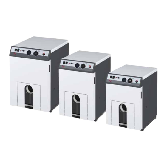
ACV N1 Installation, Operation And Maintanance Manual
Hide thumbs
Also See for N1:
- Manual (3 pages) ,
- Product manual (49 pages) ,
- Installation, operating and maintanance instructions (20 pages)
Table of Contents

Summary of Contents for ACV N1
- Page 1 INSTALLATION, OPERATION AND MAINTENANCE INSTRUCTIONS N1 / N2 / N3 EN • 1 664Y5700 • D...
-
Page 2: Table Of Contents
DHW Performance Combustion Characteristics INSTALLATION Chimney Connection Characteristics Chimney Connection Heating Connection Electrical Connection N + Smart installation, with ACV control device STARTING UP Filling the Heating Circuits Starting up the Boiler MAINTENANCE Recommendation Boiler Maintenance Inspection of the Safety devices... -
Page 3: Introduction
INTRODUCTION WHO SHOULD READ THESE INSTRUCTIONS APPLICABLE STANDARDS The manual should be read by: The appliances described in this manual were certified in accordance - The specifying engineer with European standards (European Directive 92/42/EEC “Efficiency”). - The installer They also bear the Belgian label "OPTIMAZ" (oil boiler). - The user - The maintenance technician SYMBOLS... -
Page 4: User's Guide
5. Manual reset safety thermostat (allows to reset the boiler after a primary circuit fluid overheat). 6. Control thermostat (allows to adjust the boiler temperature between 60°C (min. position) and 90°C (max. position)) SAFETY CUTOUT OF THE ACV BURNER If the burner has stopped. The burner indicator lights up. (fig. 2) 2. -
Page 5: Appliance Description
• A minimum thermostat, fitted at the rear of the boiler and preset at 45°C, delays the heating pump activation. This prevents the risks of corrosion of the combustion chamber. Production of domestic hot water The “N” boilers can be combined with any ACV hot water production tank. CONSTRUCTION Outer body The outer body which holds the primary water is made from STW 22 heavy gauge steel. -
Page 6: Technical Characteristics
TECHNICAL CHARACTERISTICS GENERAL MAXIMUM OPERATING CONDITIONS The appliances are delivered fully assembled, tested and packaged Maximum Service Pressure (DHW tank full of water) on a wooden support, protected by anti-shock corner pieces and - Primary circuit : ..............3 bar wrapped in a heatshrunk plastic film. -
Page 7: Installation
INSTALLATION A. High-level fresh air supply CHIMNEY CONNECTION CHARACTERISTICS B. Low-level fresh air supply C. Draught stabilizer Important D. Manhole opening • Never obstruct the air vents. E. Chimney height • Do not store any flammable products in the boiler room. F. -
Page 8: Heating Connection
INSTALLATION HEATING CONNECTION ELECTRICAL CONNECTION Power supply Example of single circuit connection (fig. 8) The boiler operates on a single-phase 230V/50 Hz supply. 1. Primary circuit filling valve 2. Check valve A fuse box should be installed outside the boiler, containing a circuit 3. - Page 9 INSTALLATION N1/N2/N3 boiler wiring diagram (fig. 11) Y/Gr 1. ON/OFF master switch 2. Minimum thermostat set at 45°C (T.O.D.) 3. Summer/winter switch 4. Manual reset high limit thermostat (103°C max.) 5. Burner 6. Safety cutout warning indicator 7. Room thermostat (option) 8.
-
Page 10: N + Smart Installation, With Acv Control Device
INSTALLATION N + SMART INSTALLATION, WITH ACV CONTROL DEVICE Installation with 2 heating pumps (fig. 12) Room thermostat 2. Heating pump 3. DHW charging pump 4. Boiler Control BC 01 or BC 03 5. Hot water production tank Smart 100L fig. - Page 11 INSTALLATION Electrical connection of BC 01 with 2 pumps Room thermostat 2. Heating pump 3. DHW charging pump 4. Electrical supply connection plug of the boiler 5. Hot water production tank Smart 100L 6. Power supply 9 10 11 12 13 14 15 16 17 18 19 20 230 V 50Hz T2 S3 Electrical connection of BC 01 with 1 motorised diverting valve + 1 pump...
-
Page 12: Starting Up
It is compulsory to have the boiler serviced once a year. Maintenance and the burner control must be performed by a qualified engineer. IMPORTANT If your "N" boiler is combined to an ACV hot water BOILER MAINTENANCE (fig. 15) production tank, it is essential to fill the DHW circuit before starting to fill the heating (primary) circuit. -
Page 13: Declaration Of Conformity - Ec
EN • 13 664Y5700 • D... - Page 14 EN • 14 664Y5700 • D...
- Page 15 EN • 15 664Y5700 • D...
- Page 16 EN • 16 664Y5700 • D...


Need help?
Do you have a question about the N1 and is the answer not in the manual?
Questions and answers