Table of Contents
Advertisement
Quick Links
Download this manual
See also:
Owner's Manual
Brief introduction to maintenance handbook of HS800UTV
The handbook is edited by Technical Center of Chongqing Huansong Industries
(Group) Co., Ltd., and is supplied to dealers and technicians as document of technique.
Mainly, the handbook gives methods to check, maintain and repair utility terrain
vehicles (UTV), and supplies some relevant technique and performance data. Some
techniques and method inside may be used to check, maintain and repair other models of
UTV, although it is mainly for HS800UTV.
Please read the handbook through and fully understand it; otherwise, any improper
repairing and amounting would bring you problems, and accident may occur in your use.
Proper use and maintenance can guarantee UTV being driven safely, reduce its
malfunction, and help the vehicle remain its best performance.
The standards, performances and specifications mentioned in interpretation are
based on the sample in design, and they are subject to changes according to the
product's improvement without prior notice.
First version , March,2010
Published by Chongqing Huansong Industries (Group) Co., Ltd.
Chongqing Huansong Industries (Group) Co., Ltd holds the copy right.
No publishing and reprinting without permission.
FOREWORD
Advertisement
Table of Contents
Troubleshooting

Related Manuals for Hisun HS800UTV


Summary of Contents for Hisun HS800UTV
- Page 1 FOREWORD Brief introduction to maintenance handbook of HS800UTV The handbook is edited by Technical Center of Chongqing Huansong Industries (Group) Co., Ltd., and is supplied to dealers and technicians as document of technique. Mainly, the handbook gives methods to check, maintain and repair utility terrain vehicles (UTV), and supplies some relevant technique and performance data.
-
Page 2: Table Of Contents
CONTENT CHAPTER 1 GENERAL INFORMATION GENERAL INFORMATION……………………………………………………………………1 WATNINGS CAUTIONS AND NOTES……………………………………………………1 DESCRIPTION……………………………………………………………………………………2 IDENTIFICATION CODE……………………………………………………………………… 3 Frame No. ………………………………………………………………………………… 3 Engine No. ………………………………………………………………………………… 3 SAFETY ………………………………………………………………………………………… 4 Handing gasoline safely…………………………………………………………………… 4 Cleaning parts……………………………………………………………………………… 5 Warning labels……………………………………………………………………………… 5 SERIAL NUMBERS…………………………………………………………………………… 6 FASTENERS…………………………………………………………………………………… 6 Torque specifications ………………………………………………………………………... - Page 3 Wrenches ………………………………………………………………………………… 11 Adjustable wrenches …………………………………………………………………… 12 Socket wrenches, ratchets and handles ……………………………………………… 12 Impact drivers …………………………………………………………………………… 13 Allen wrenches…………………………………………………………………………… 13 Torque wrenches………………………………………………………………………… 14 Torque adapters ………………………………………………………………………… 14 Pliers……………………………………………………………………………………… 15 Snap ring pliers…………………………………………………………………………… 15 Hammers ………………………………………………………………………………… 16 Ignition grounding tool…………………………………………………………………… 16 PRECISION MEASURING TOOLS …………………………………………………………...
- Page 4 Removal…………………………………………………………………………………… 26 Installation………………………………………………………………………………… 27 Interference fit …………………………………………………………………………… 28 Seal replacement………………………………………………………………………… 29 STORAGE……………………………………………………………………………………… 30 Storage area selection…………………………………………………………………… 30 Preparing the motorcycle for storage …………………………………………………… 30 Returning the UTV to service…………………………………………………… 30 TROVBLESHOOTING……………………………………………………………………… 31 ENGINE PRINCIPLES AND OPERATING REQUIREMENTS………………………… 32 STARTING THE ENGINE ………………………………………………………………… 32 Engine is cold ……………………………………………………………………………...
- Page 5 FUEL SYSTEM……………………………………………………………………………… 41 Rich mixture……………………………………………………………………………… 41 Lean mixture……………………………………………………………………………… 41 ENGINE………………………………………………………………………………………… 42 Engine smoke……………………………………………………………………………… 42 Black smoke ……………………………………………………………………………… 42 Blue smoke………………………………………………………………………………… 42 White smoke or steam…………………………………………………………………… 42 Low engine compression ………………………………………………………………… 42 High engine compression ……………………………………………………………… 43 Engine overheating (cooling system) ………………………………………………… 43 Engine overheating (engine)……………………………………………………………...
- Page 6 TEST PROCEDURES………………………………………………………………………… 52 Voltage test……………………………………………………………………………… 52 Voltage drop test………………………………………………………………………… 52 Peak voltage test………………………………………………………………………… 53 Continuity test……………………………………………………………………………… 53 Testing for a short with a self-powered test light or ohmmeter……………………… 54 Testing for a short with a test light or voltmeter………………………………………… 54 BRAKE SYSTEM………………………………………………………………………………...
- Page 7 ENGINE GEARBOX LUBRICATION OIL PARTH CIRCUIT……………………………… 81 CHAPTER 3 MAINTENCE AND ADJUSTMENT OF THE UTV MAINTENANCE SCHEDULE……………………………………………………………… 83 ENGINE Adjusting the valve clearance…………………………………………………………… 85 Checking the spark plug ………………………………………………………………… 88 Checking the ignition timing……………………………………………………………… 89 Measuring the compression pressure………………………………………………… 90 Checking the engine oil level ……………………………………………………………...
- Page 8 Checking the steering system………………………………………………………… 111 Adjusting the toe-in …………………………………………………………………… 112 Adjusting the front and rearshock absorbers………………………………………… 113 Checking the tires ……………………………………………………………………… 114 Checking the wheels…………………………………………………………………… 116 Checking and lubricating the cables ………………………………………………… 116 ELECTRICAL Checking and charging the battery…………………………………………………… 117 Checking the fuses ……………………………………………………………………...
- Page 9 CHAPTER 5 CHASSIS MALFUNCTION INSPECTION…………………………………………………………… 181 DIRECTION SYSTEM The structure of the steering…………………………………………………………… 184 The structure of steering wheel part…………………………………………………… 188 Diassembling the parts of the steering wheel ………………………………………… 188 Checking the parts of the steering wheel……………………………………………… 188 Diassembling the steering column parts……………………………………………… 189 Checking and service the steering column parts………………………………………...
- Page 10 FOOTREST ASSEMBLY ………………………………………………………………… 215 WHEEL AND TYRE PARTS ……………………………………………………………… 218 Front wheels……………………………………………………………………………… 218 Rear wheels……………………………………………………………………………… 219 Checking the wheel tyre………………………………………………………………… 220 Checking the wheel hub………………………………………………………………… 220 Installing the wheel hub………………………………………………………………… 221 Installing the wheel tyre………………………………………………………………… 221 Specification of wheel and tyre………………………………………………………… 222 TRANSMISSION SYSTEM …………………………………………………………………...
- Page 11 Installing the rear arms and rear shock absorber …………………………………… 256 COOLING SYSTEM………………………………………………………………………… 257 Radiator ………………………………………………………………………………… 257 Checking the radiator…………………………………………………………………… 261 Installing the radiator…………………………………………………………………… 262 Oil cooler …………………………………………………………………………… 263 Checking the oil cooler ………………………………………………………………… 265 Water pump……………………………………………………………………………… 266 Disassembling the water pump ……………………………………………………… 270 Checking the water pump………………………………………………………………...
- Page 12 Checking the starter motor …………………………………………………………… 296 Assembling the starter motor ………………………………………………………… 297 CHARGING SYSTEM …………………………………………………………………… 298 Circuit diagram………………………………………………………………………… 298 TROUBLESHOOTING …………………………………………………………………… 299 LIGHTING SYSTEM ……………………………………………………………………… 301 CIRCUIT DIAGRAM ……………………………………………………………………… 301 TROUBLESHOOTING …………………………………………………………………… 302 CHECKING THE LIGHTING SYSTEM ………………………………………………… 303 If the headlights fail to come on ……………………………………………………… 303 If the taillights fail to come on ………………………………………………………...
- Page 13 Typical components of EMS………………………………………………………………323 Layout of EMS components………………………………………………………………324 COMPONENTS OF EMS Electronic control unit …………………………………………………………………… 324 Multec 3.5 injectors ……………………………………………………………………… 325 Throttle body assembly(with stepper motor) …………………………………………329 Engine coolant temperature sensor …………………………………………………… 331 Intake air pressure and temperature sensor ……………………………………………331 Oxygen sensor ……………………………………………………………………………...
- Page 14 SHOCK ABSORBER MALFUNCTION………………………………………………… 347 Malfunction ……………………………………………………………………………… 347 UNSTABLE HANDLING…………………………………………………………………… 347 Unstable handling ……………………………………………………………………… 345 LIGHTING SYSTEM………………………………………………………………………… 348 Head light is out of work………………………………………………………………… 348 Bulb burnt out…………………………………………………………………………… 348 HS800UTV WIRING DIAGRAM…………………………………………………………… 349 - 13 -...
-
Page 15: General Information
GENERAL INFORMATION GENERAL INFORMATION The text provides complete information on maintenance, tune-up repair and overhaul, Hundreds of photographs and illustrations created during the complete disassembly of four wheel all-terrain vehicles (UTV) guide the reader through every job,All procedures are in step-by-step format and designed for the reader who may be working on the UTV for the first time. -
Page 16: Description
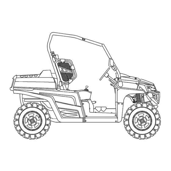
GENERAL INFORMATION DESCRIPTION 1. Headlights 2. Front shock absorber spring preload Adjusting ring 3. Rear brake fluid reservoir 4. Parking brake lever 5. Driver seat 6. Battery 7. Fuses 8. Left shoulder protection plate 9. Driver seat belt 10. Air filter case (engine and air intake duct) 11. -
Page 17: Identification Code
GENERAL INFORMATION IDENTIFICATION CODE Frame No. Frame No. is carved on the right side of front main frame Engine No. Engine NO. Is carved on the right side of the engine, Figure. -
Page 18: Safety
GENERAL INFORMATION SAFETY Professional mechanics can work for years and never sustain a serous injury or mishap. Follow these guidelines and practice common sense to safely service the utility terrain venires Do not operate the utility terrain venires in an enclosed area venires The exhaust gasses contain carbon monoxide. -
Page 19: Cleaning Parts
GENERAL INFORMATION When working of the fuel system, work outside or in a well-ventilated area. Do not add fuel to the fuel tank or service the fuel system while the UTV is near open flames, sparks or where someone is smoking .Gasoline vapor is heavier than air, it collects in low areas and is more easily ignited than liquid gasoline. -
Page 20: Serial Numbers
GENERAL INFORMATION SERIAL NUMBERS Serial and identification numbers are stamped on various locations on the frame, engine and carburetor body. Record these numbers in the Quick Reference Data section in the front of the manual. Have these numbers available when ordering parts. FASTENERS Proper fastener selection and installation is important to ensure the motorcycle operates as designed and can be serviced efficiently. -
Page 21: Cotter Pins
GENERAL INFORMATION design and quality Cotter Pins A cotter pin is a split metal pin inserted into a hole or slot to prevent a fastener from loosening. In certain applications, such as the rear axle on an UTV or motorcycle, the fastener must be secured in this way. -
Page 22: Shop Supplies
GENERAL INFORMATION After installing a snap ring. Make sure it seats completely Wear eye protection when removing and installing snap rings SHOP SIPPLIES Lubricants and Fluids Periodic lubrication help ensure a long service life for any type of equipment. Using the correct type of lubricant is as important as performing the lubrication service. -
Page 23: Brake Fluid
GENERAL INFORMATION Typical multipurpose grease is NLGI No.2. For specific applications, manufacturers may recommend water-resistant type grease or one with an additive such as molybdenum disulfide (MoS2). Brake fluid Brake fluid is the hydraulic fluid used to transmit hydraulic pressure (force) to the wheel brakes. Brake fluid is classified by the Department of Transportation (DOT). -
Page 24: Gasket Remover
GENERAL INFORMATION crankcase halves, only a sealant is used. Follow the manufacturer’s recommendation when using a sealant. Use extreme care when choosing a sealant different sealant based on its resistance to heat, various fluids and its sealing capabilities. Gasket Remover Aerosol gaskets remover can help remove stubborn gasket. -
Page 25: Screwdrivers
GENERAL INFORMATION from a quality tool combinations and offer substantial savings when complicated, specialized tools can be added. Screwdrivers Screwdrivers of various lengths and types are mandatory for the simplest tool kit. The two basic types are the slotted tip (flat blade) and the Phillips tip. These are available in sets that often include an assortment of tip size and shaft lengths. -
Page 26: Adjustable Wrenches
GENERAL INFORMATION For stubborn or damaged fasteners, the 6-point provides superior holding because it contacts the fastener across a wider area at all six edges. For general use, the 12-point works well. It allows the wrench to be removed and reinstalled without moving the handle over such a wide are. -
Page 27: Impact Drivers
GENERAL INFORMATION for more durability. Compare the size and wall thickness of a 19-mmhand socket (A, Figure 9) and the 19-mm impact socket (B). Use impact sockets when using an impact driver or air tools. Use hand sockets with hand-driven attachments WARNING Do not use hand sockets with air or impact tools because they may shatter and cause... -
Page 28: Torque Wrenches
GENERAL INFORMATION Torque Wrenches Use a torque wrench with a socket, torque adapter or similar extension to tighten a fastener to a measured torque. Torque wrenches come in several drive sizes (1/4, 3/8, 1/2 and 3/4) and have various methods of reading the torque value. The drive size indicates the size of the square drive that accepts the socket, adapter or extension. -
Page 29: Pliers
GENERAL INFORMATION TW is the torque setting or dial reading on the wrench. TA is the torque specification and the actual amount of torque that is applied to the fastener. A is the amount that the adapter increases (or in some cases reduces) the effective lever length as measured along the centerline of the torque wrench. -
Page 30: Hammers
GENERAL INFORMATION interchangeable ones of various sizes and angles. For general use, select a convertible type pliers with interchangeable tips (Figure 17). WARNING Snap rings can slip and fly off when removing and installing them. Also, the snap ring pliers tips may break. Always wear eye protection when using snap ring pliers. -
Page 31: Feeler Gauge
GENERAL INFORMATION Heavy-handed use of measuring tools produces less accurate results. Hold the tool gently by the fingertips to easily feel the point at which the tool contacts the object. This feel for the equipment produces more accurate measurements and reduces the risk of damaging the tool or component. Refer to the following sections for specific measuring tools. -
Page 32: Micrometers
GENERAL INFORMATION Micrometers A micrometer is an instrument designed for linear measurement using the decimal divisions of the inch or meter (Figure 22). While there are many types and styles of micrometers, most of the DECIMAL PLACE VALUES* Indicates 1/10 (one tenth of an inch or millimeter) 0.01 Indicates 1/100 (one one-hundredth of... -
Page 33: Care
GENERAL INFORMATION ensure that the proper amount of pressure is applied. b. If the adjustment is correct, the 0 mark on the thimble will align exactly with the 0 mark on the sleeve line. If the marks do not align, the micrometer is out of adjustment. c. -
Page 34: Standard Inch Micrometer
GENERAL INFORMATION When reading a metric micrometer, add the number of millimeters and half-millimeters on the sleeve line to the number of one one-hundredth millimeters on the thimble. Perform the following steps while referring to Figure 25. 1. Read the upper half of the sleeve line and count the number of lines visible. -
Page 35: Telescoping And Small Bore Gauges
GENERAL INFORMATION amount between the lines. For accurate readings in ten-thousandths of an inch (0.0001 in), use a vernier inch micrometer. 4. Add the readings from Steps 1-3. Telescoping and Small Bore Gauges Use telescoping gauges (Figure 28) and small bore gauges (Figure 29) to measure bores. -
Page 36: Compression Gauge
GENERAL INFORMATION manufacturer’s instructions. Compression Gauge A compression gauge (Figure 33) measures combustion chamber (cylinder) pressure, usually in PSI or kg/ cm . The gauge adapter is either inserted or screwed into the spark plug hole to obtain the reading. Disable the engine so it does not start and hold the throttle in the wide-open position when performing a compression test An engine that does not have adequate compression cannot be properly... -
Page 37: Resistance
GENERAL INFORMATION battery are DC circuits. Alternating current (AC) means the electricity flows in one direction momentarily and then switches to the opposite direction. Alternator output is an example of AC voltage. This voltage must be changed or rectified to direct current to operate in a battery powered system. Resistance Resistance is the opposition to the flow of electricity within a circuit or component and is measured in ohms. -
Page 38: Removing Frozen Fasteners
GENERAL INFORMATION proceeding. 8. To prevent objects or debris from falling into the engine, cover all openings. 9. Read each procedure thoroughly and compare the illustrations to the actual components before starting the procedure. Perform the procedure in 10. Recommendations are occasionally made to refer service to a dealership or specialist. In these cases, the work can be performed more economically by the specialist than by the home mechanic. -
Page 39: Removing Broken Fasteners
GENERAL INFORMATION the normal way. If the screw head is too damaged to use this method, grip the head with locking pliers and twist the screw out. Avoid applying heat unless specifically instructed. Heat may melt, warp or remove the temper from parts. -
Page 40: Removing Hoses
GENERAL INFORMATION Thread the stud removal tool onto the stud and tighten it, or thread two nuts onto the stud. Remove the stud by turning the stud remover or the lower nut. Remove any thread locking compound from the threaded hole. Clean the threads with an aerosol parts cleaner. -
Page 41: Installation
GENERAL INFORMATION While bearing are normally removed only when damaged, there may be times when it is necessary to remove a bearing that is in good condition. However, improper bearing removal will damage the bearing and possibly the shaft or case. Note the following when removing bearings: 1. -
Page 42: Interference Fit
GENERAL INFORMATION install a bearing. 3. Step 1 describes how to install a bearing in a case half or over a shaft However, when installing a bearing over a shaft and into the housing at the same time, a tight fit is required for both outer and inner bearing races. -
Page 43: Seal Replacement
GENERAL INFORMATION CAUTION Do not heat the housing with a propane or acetylene torch. Never bring a flame into contact with the bearing or housing. The direct heat will destroy the case hardening of the bearing and will likely warp the housing. -
Page 44: Storage
GENERAL INFORMATION STORAGE Several months of non-use can cause a general deterioration of the motorcycle, UTV This is especially true in areas of extreme temperature variations. This deterioration can be minimized with careful preparation for storage. A properly stored motorcycle is much easier to return to service. Storage Area Selection When selecting a storage area, consider the following: 1. -
Page 45: Trovbleshooting
GENERAL INFORMATION 1. Remove the covers from the intake and exhaust openings. 2. Service the air filter as described in Chapter Three. 3. Inspect the cooling system. Check the drain plug and hose connections for leaks. 4. Refill the fuel tank. Turn the fuel shutoff valve on and check for fuel leaks. 5. -
Page 46: Engine Principles And Operating Requirements
GENERAL INFORMATION ENGINE PRINCIPLES AND OPERATING REQUIREMENTS An engine needs three basics to run properly: Correct air/fuel mixture Compression Engine runs A spark at the right time If one basic requirement is missing the engine will not run. STARTING THE ENGINE When experiencing engine-starting troubles, it is easy to work out of sequence and forget basic starting procedures. -
Page 47: Starting The Engine After A Fall Or After The Engine Stalls
GENERAL INFORMATION Starting the engine after a fall or after the engine stalls 1. Shift the transmission into neutral. 2. Release the hot start lever as the engine starts. 3. If the engine fails to start, refer to Flooded Engine in this section. Flooded engine If the engine fails to start after several attempts, it is probably flooded. -
Page 48: Engine Is Hot
GENERAL INFORMATION 3. If the temperature is below 32°F (0℃), open the throttle two or three times to allow the accelerator pump to feed additional fuel to the engine. 4. Pull the choke knob all the way out to richen the air/fuel mixture. NOTE Do not open the throttle when starting the engine in Step 4. -
Page 49: Engine Will Not Start
GENERAL INFORMATION repair the float assembly. 2. Shift the transmission into neutral. 3. Check that the choke knob is fully closed (pushed in). 4. Starter---Perform the following: a. Pull the hot start lever, then pull the clutch lever fully in, open the throttle fully and press the starter button for 5 seconds. -
Page 50: Spark Test
GENERAL INFORMATION for loose wire ends. On waterproof connectors, check for damage where the wires enter the connector. 6. Perform the Spark Test in this section. If there is a strong spark, perform Step 7. If there is no spark or if the spark is very weak, refer to Ignition System Testing in Chapter Ten. -
Page 51: Starter Does Not Turn Over Or Turns Over Slowly
GENERAL INFORMATION 6. If there is a strong, blue spark, the ignition system is functioning properly, Check for one or more of the following possible malfunctions: a. Faulty fuel system component. b. Flooded engine. c. engine damage(low compression). 7. If the spark was weak (white or yellow) or if there was no spark, perform the peak voltage checks described under Ignition System Testing. -
Page 52: Engine Backfires On Deceleration
GENERAL INFORMATION conditions: a. Incorrect float level adjustment. b. Plugged pilot jet or pilot system. 2. Faulty accelerator pump. 3. Loose exhaust pipe-to-cylinder head connection. 4. Intake air leak. 5. Incorrect ignition timing or a damaged ignition system can cause these conditions. Perform the Peak Voltage Tests to isolate the damaged ignition system component. -
Page 53: Low Engine Power
GENERAL INFORMATION 7. Intake air leak. 8. Incorrect ignition timing 9. Low engine compression Low Engine Power 1. Support the UTV in a stand with the rear wheel off the ground. then spins freely. If the wheel does not spin freely. Check for the following conditions: a. -
Page 54: Poor Idle Or Low Speed Performance
GENERAL INFORMATION Incorrect oil level (too high or too low) Contaminated oil Worn or damaged valve train assembly Engine overheating 6. If the engine knocks when it is accelerated or when running at high speed. Check for one or more of the following possible malfunctions: Incorrect type of fuel Lean fuel mixture... -
Page 55: Fuel System
GENERAL INFORMATION FUEL SYSTEM The following section isolates common fuel system problems under specific complaints. If there is a good spark. Poor fuel flow may be preventing the correct amount of fuel from being supplied to the spark plug. Troubleshoot the fuel system as follows: Clogged fuel tank breather hose Check that there is a sufficient amount of fuel in the rank After attempting to start the engine. -
Page 56: Engine
GENERAL INFORMATION ENGINE Engine Smoke The color of engine smoke can help diagnose engine problems or operating conditions Black smoke Black smoke is an indication of a rich air/fuel mixture Blue smoke Blue smoke indicates that the engine is burning oil in the combustion chamber as it leaks past worn valve stem seals and piston rings. -
Page 57: High Engine Compression
GENERAL INFORMATION c. Warped or cracked cylinder head. 3. Damaged decompress or assembly. High Engine Compression 1. Faulty decompress or assembly. 2. Excessive carbon buildup in the combustion chamber. Engine Overheating (Cooling System) WARNING Do not remove the radiator cap, coolant drain plug or disconnect any coolant hose immediately after or during engine operation. -
Page 58: Detonation
GENERAL INFORMATION Detonation Detonation is the violent explosion of fuel in the combustion chamber before the proper time of ignition. Using low octane gasoline is a common cause of detonation. Even when using a high octane gasoline, detonation can still occur. Other causes are over-advanced ignition timing, lean air/fuel mixture at or near full throttle, inadequate engine cooling, or the excessive accumulation of carbon deposits in the combustion chamber. -
Page 59: Englne Lubrication
GENERAL INFORMATION Valve sticking in guide. Broken valve spring. Low oil pressure. Clogged cylinder oil hole or oil passage. ENGLNE LUBRICATION An improperly operating engine lubrication system quickly leads to engine seizure. Check the engine oil level and oil pressure. High Oil Consumption or Excessive Exhaust Smoke 1. -
Page 60: Oil Level Too Low
GENERAL INFORMATION Oil Level Too Low 1. Oil level not maintained at correct level 2. Worn piston rings. 3. Worn cylinder. 4. Worn valve guides. 5. Worn valve guide seals. 6. Piston rings incorrectly installed during engine overhaul. 7. External oil leakage. 8. - Page 61 GENERAL INFORMATION cannot be viewed to ensure that the engine is positioned at TDC on its compression stroke. To determine when the engine is approaching TDC on its compression stroke, or whether it is 360°off. Observe the following two indicators to predict engine position.
-
Page 62: Electrical Testing
GENERAL INFORMATION turns, reposition the countershaft slightly and then relock it in position with the holding tool. After several attempts, you will get a feel of the transmission play and know what direction the countershaft should be turned and locked. NOTE If a large amount of air escapes from the exhaust pipe or through the carburetor, the air is leaking through on open... -
Page 63: Intermittent Problems
GENERAL INFORMATION terminals in the electrical connector Make sure the terminals on the end of each wire are pushed all the way into the connector. If not. Carefully push them in with a narrow blade screwdriver Check the wires where they connect to the terminals for damage Make sure all terminals within the connector are clean and free of corrosion. -
Page 64: Electrical Component Replacement
GENERAL INFORMATION problem. CAUTION A heat gun or hair dryer will quickly raise the heat of the component being tested. Do not apply heat directly to the ICM or use heat in excess of 60℃ (140℉) on any electrical component. If available, monitor heat with an infrared thermometer. -
Page 65: Ohmmeter
GENERAL INFORMATION Use a self-powered test light as follows: 1. Touch the test leads together to make sure the light bulb goes on. If not, correct the problem before using it in a test procedure. 2. Select two points within the circuit where there should be continuity. 3. -
Page 66: Test Procedures
GENERAL INFORMATION point to another. The problem can be isolated to a particular place in the circuit Pay attention to the following when using a jumper wire: 1. Make sure the jumper wore gauge (thickness) is the same as that used in the circuit being tested. -
Page 67: Peak Voltage Test
GENERAL INFORMATION so the voltmeter indicates 0 volts. The greater the resistance in a circuit. The greater the voltage drop reading. To perform a voltage drop: 1. Connect the positive meter test lead to the electrical source (where electricity is coming from). 2. -
Page 68: Testing For A Short With A Self-Powered Test Light Or Ohmmeter
GENERAL INFORMATION Testing for a short with a self-powered test light or ohmmeter 1. Disconnect the negative battery cable. 2. Remove the blown fuse. 3. Connect one test lead of the test light or ohmmeter to the load side (battery side) of the fuse terminal in the starter relay. -
Page 69: Brake Drag
GENERAL INFORMATION can also enter the system from loose or damaged hose fittings. Air in the hydraulic system causes a soft or spongy brake lever action. This condition is noticeable and reduces brake performance. When it is suspected that air has entered the hydraulic system, flush the brake system and bleed the brakes as described in Chapter Fifteen. -
Page 70: Hard Brake Lever Or Pedal Operation
GENERAL INFORMATION 6. Contaminated brake fluid and hydraulic passages. 7. Restricted brake hose joint. 8. Loose brake disc mounting bolts. 9. Damaged or misaligned wheel. 10. Incorrect wheel alignment. 11. Incorrectly installed brake caliper. 12. Damaged front or rear wheel. Hard Brake Lever or Pedal Operation When applying the brakes and there is sufficient brake performance but the operation of brake lever feels excessively hard, check for the following possible causes:... -
Page 71: Leaking Brake Caliper
GENERAL INFORMATION Leaking Brake Caliper 1. Damaged dust and piston seals. 2. Damaged cylinder bore. 3. Loose caliper body bolts. 4. Loose banjo bolt. 5. Damaged banjo bolt washers. 6. Damaged banjo bolt threads in caliper body. Leaking Master Cylinder 1. -
Page 72: Specifications
SPECIFICATIONS SPECIFICATIONS HOW TO CONVERSION TABLE OF UNIT (1)How to use conversion table All the specified documents in this manual are taken SI and Metric as unit. With the following conversion table, metric unit could be conversed into imperial unit. Sample: METRIC MULTIPLY... -
Page 73: Geberar Specifications
SPECIFICATIONS GEBERAR SPECIFICATIONS Item Standard Dimensions : Overall length 2,700mm (106.3in) Overall width 1,360mm(53.5 in) Overall height 1,840mm(72.4in) Seat height 800mm(31.50in) Wheelbase 1,940mm(76.4in) Minimum ground clearance 260 mm(10.2 in) Minimum turning radius 6,730mm(265.0 in) Basic weight : With oil and full fuel tank 547kg (1,206 lb) Engine : Engine type... - Page 74 SPECIFICATIONS Item Standard Ignition system Type/quantity 33200-F68 / 1 Spark plug DCPR7E / 1 (NGK) Type/manufacturer 0.8-0.9 mm(0.031-0.035 in) Spark plug gap Clutch type Wet ,centrifugal automatic Transmission Primary reduction system V-belt Secondary reduction system Shaft drive Transmission type V-belt automatic Operation Right hand operation Single speed automatic...
- Page 75 SPECIFICATIONS Item Standard Suspension Front suspension Double wishbone Rear suspension Double wishbone Shock absorber Front shock absorber Coil spring/oil damper Rear shock absorber Coil spring/oil damper Wheel travel Front wheel travel 130mm (5.12 in) Rear wheel travel 150mm (5.91 in) Electrical Ignition system C.D.I.
-
Page 76: Engine Specifications
SPECIFICATIONS ENGINE SPECIFICATIONS Item Standard Limit Cylinder head Warp limit ---- 0.03 mm (0.0012 in) Cylinder Bore size 91.016 ~ 91.030mm ---- Measuring point (3.544~ 3.584 in) 50 mm (1.97 in) Camshaft Drive method ---- Cam dimensions Intake 31.95 ~ 32.11mm “A”... - Page 77 SPECIFICATIONS Item Standard Limit Cam chain No. of links Cam chain adjustment method Automatic Rocker arm/rocker arm shaft Rocker arm inside diameter 12.011~ 12.018 mm (0.4729 ~ 0.4731 in) Shaft outside diameter 11.982~ 11.989 mm ---- (0.4717 ~ 0.4720 in) Arm-to-shaft clearance 0.022 ~ 0.036 mm ----...
- Page 78 SPECIFICATIONS Item Standard Limit Stem-to-guide clearance 0.010 ~ 0.037 mm 0.08 mm (0.0004 ~ 0.0015 in) (0.0031 in) 0.025 ~ 0.052 mm 0.10 mm (0.0010 ~ 0.0020 in) (0.0039 in) Stem runout limit ---- 0.01 mm (0.0004 in) Valve seat width 0.9 ~ 1.1 mm ---- (0.0354 ~ 0.0433 in)
- Page 79 SPECIFICATIONS Item Standard Limit Piston Piston to cylinder clearance 0.050 ~ 0.070 mm 0.15 mm (0.0020 ~ 0.0028 in) (0.0059 in) Piston size “D” 90.940 ~ 90.955mm ---- (3.5803 ~ 3.5809 in) ---- Measuring point “H” 4.0 mm (0.15 in) ---- Piston off-set 0.5mm(0.0394 in)
- Page 80 SPECIFICATIONS Item Standard Limit Oil ring ---- 4.0×3.40mm (0.1575× 0 .1339in) Dimensions (B×T) ---- 0.20 ~ 0.70 mm (0.0079 ~ 0.0276 in) End gap (installed) ---- 0.06 ~ 0.15 mm (0.0024 ~ 0.0059 in) Side clearance Crankshaft 90.523~ 90.577mm ---- Crank width “A”...
- Page 81 SPECIFICATIONS Item Standard Limit Shifter Shifter type Shift drum and guide bar ---- Air filter oil grade Engine oil ---- Oil pump Oil filter type Chartaceous ---- Oil pump type Trochoid Tip clearance 0.15 mm ---- (0.0059 in) ---- Side clearance 0.03 ~ 0.10 mm ---- (0.0012 ~ 0.0039 in)
-
Page 82: Chassis Specifications
SPECIFICATIONS CHASSIS SPECIFICATIONS Item Standard Limit Steering system Type Rack and pinion ---- Front suspension Shock absorber travel 58 mm (2.28 in) ---- Spring free length 320 mm (12.60 in) ---- Spring fitting length 245 mm (9.65in) ---- Spring rate 21 N/mm(2.1kg/mm, 117.60lb/in) ---- Stroke... - Page 83 SPECIFICATIONS Item Standard Limit Front disc brake Type Dual ---- Disc outside diameter × thickness 200 × 3.5 mm (7.87 × 0.14 in) ---- Pad thickness inner 9.0 mm (0.35 in) ---- Pad thickness outer 9.0 mm (0.35 in) ---- Master cylinder inside diameter 19.0mm (0.75in) ----...
-
Page 84: Electrical Specifications
SPECIFICATIONS ELECTRICAL SPECIFICATIONS Item Standard Limit Voltage 12 V ---- Ignition system Ignition timing (BTDC) 15°±1°before TDC ---- Advancer type ECU Digital type ---- C.D.I. Pickup coil resistance/color 459 ~ 561 Ωat 20 °C (68 °F)/ ---- White/Red – White/Green ---- Rotor rotation direction sensing coil 0.063 ~ 0.077 Ωat 20 °C (68 °F)/... - Page 85 SPECIFICATIONS Item Standard Limit Electric starter system Type Constant mesh type ---- Starter motor ---- Output 0.8 kW ---- Armature coil resistance 0.025 ~ 0.035 Ωat 20 °C (68 °F) ---- Brush overall length 12.5 mm (0.49 in) 5 mm(0.20 in) Spring force 7.65 ~ 10.01 N ----...
-
Page 86: Tightening Torques
SPECIFICATIONS TIGHTENING TORQUES Engine tightening torques Thread Tightening torque Part to be tightened Part name Q’ty Remarks size m · kg ft · lb Cylinder head Bolt Bolt Spark plug — Cylinder head (exhaust pipe) Stud bolt Cylinder head cover Bolt Tappet cover (exhaust) —... - Page 87 SPECIFICATIONS Thread Tightening torque Part to be tightened Part name Q’ty Remarks size m · kg ft · lb Bolt Bolt Crankcase Bolt Bearing housing (clutch housing Bolt assembly) Bolt Air duct assembly 1 bracket Oil seal (engine cooling fan pulley) Bolt Retainer Drive belt case...
- Page 88 SPECIFICATIONS Thread Q’ty Remarks Part to be tightened Part name size ft · lb m.kg Left-hand Shift rod locknut (select lever unit) — threads Shift rod locknut (shift arm side) — Select lever unit Bolt Plug (right crankcase) — Water pump assembly Bolt Water pump housing cover Bolt...
-
Page 89: Chassis Tightening Torques
SPECIFICATIONS Chassis tightening torques Thread Tightening torque Part to be tightened Remarks size m · kg ft · lb Rubber connecting bracket 1(or 2) and frame Engine and Rubber connecting bracket 2 (front) Engine and Rubber connecting bracket 1 (rear) Rear upper arm and frame Rear lower arm and frame Rear knuckle and rear upper arm... - Page 90 SPECIFICATIONS Thread Tightening torque Part to be tightened Remarks size m · kg ft · lb Seat belt and ceiling (enclosure) 7/16 Front wheel and front wheel hub Front wheel hub and constant velocity joint of half 26.0 Stake shaft Steering knuckle and brake disc guard Front brake caliper and front wheel steering knuckle Front brake hose union bolt...
-
Page 91: General Tightening Torque Specifications
SPECIFICATIONS GENERAL TIGHTENING TORQUE SPECIFICATIONS This chart specifies tightening torques for standard fasteners with a standard ISO thread pitch. Tightening torque specifications for special components or assemblies are provided for each chapter of this manual. To avoid warpage, tighten multi-fastener assemblies in a crisscross pattern and progressive stages until the specified tightening torque is reached. -
Page 92: Lubrication Pionts And Lubricant Types
SPECIFICATIONS LUBRICATION PIONTS AND LUBRICANT TYPES Engine Lubrication points Lubricant Oil seal lips Apply lithium-soap-based grease Bearings Apply engine oil O-rings Apply lithium-soap-based grease Piston, piston ring Apply engine oil Piston pin Apply engine oil Buffer boss and balancer drive gear Apply engine oil Crankshaft seal and spacer Apply engine oil... -
Page 93: Chassis
SPECIFICATIONS CHASSIS Lubrication points Lubricant Lip of oil seal (full) Light lithium-base frease o-ring(full) Light lithium-base frease Steering shaft (upper end ,lower end) Light lithium-base frease Ball connection of steering pushing rod Light lithium-base frease Front wheel fork(ball-shaped joint) Light lithium-base frease Front wheel fork (ball-shaped joint) Light lithium-base frease Front wheel bearing... -
Page 94: Hydrographic Chart
SPECIFICATIONS HYDROGRAPHIC CHART Hydrographic chart :Pressure - 80-... - Page 95 SPECIFICATIONS LUBRICATION OIL WAY LUBRICATION OIL WAY :Pressure :splashing oil - 81-...
-
Page 96: Engine Gearbox Lubrication Oil Parth Circuit
SPECIFICATIONS Engine gearbox lubrication oil path circuit Gearbox lubrication oil path circuit :Pressure :splashing oil - 82-... -
Page 97: Maintence And Adjustment Of The Utv
MAINTENCE AND ADJUSTMENT OF THE UTV MAINTENCE AND ADJUSTMENT OF THE UTV NOTE: The correct maintenance and adjustment are necessary to ensure vehicle and normal driving The repair personnel should be familiar with the contents of this article. MAINTENANCE SCHEDULE EVERY INITAL Whichever... - Page 98 MAINTENCE AND ADJUSTMENT OF THE UTV · Check condition. · Spark plug Adjust gap and clean. ○ ○ ○ ○ ○ · Rep; ace if necessary. · Check and adjusted idle speed/starter Carburetor* operation. ○ ○ ○ ○ · Adjust if necessary. ·...
-
Page 99: Engine
MAINTENANCE AND ADJUSTMENT OF THE UTV ENGINE Adjusting the valve clearance NOTE: ·The valve clearance must be adjusted when the engine is cool to the touch. · Adjust the valve clearance when the piston is at the Top Dead Center TDC) on the compression stroke. - Page 100 MAINTENANCE AND ADJUSTMENT OF THE UTV 3. Check: ·valve clearance ·Beyond the standard Adjust. Valve clearance (cold) Intake 0.08 ~ 0.12 mm (0.0031 ~ 0.0047 in) Exhaust 0.12 ~ 0.16 mm (0.0047 ~ 0.0063 in) 4. calibration adjusting tools ○ Spin the crank, when the rotoflex’s scale shows 1, it is cylinder 1’s timing;...
- Page 101 MAINTENANCE AND ADJUSTMENT OF THE UTV Adjust the valve clearance of cylinder 1, and cylinder 2 the same way valve clearance Lock nut ① Valve thickness gauge(gap Regulation) ② Regulator ③ ④ Adjust tools · Loosen the locknut ① · Insert a thickness gauge between the adjuster ③...
-
Page 102: Checking The Spark Plug
MAINTENANCE AND ADJUSTMENT OF THE UTV CHECKING THE SPARK PLUG 1. lift up cargo box and dismount the seat 2. Remove: pull out the spark plug cap ① 3. Check: ·spark plug type Incorrect Replace. Standard spark plug DPR8EA-9/NGK 4. Check: ·electrode ①... -
Page 103: Checking The Ignition Timing
MAINTENANCE AND ADJUSTMENT OF THE UTV CHECKING THE IGNITION TIMING NOTE: before checking the ignition timing, adjust the engine’s racing speed and throttle cable. 1. Remove: ·driver seat ·passenger seat ·console Refer to “SEATS” in chapter 5. 2. Lift the cargo bed up. 3. -
Page 104: Measuring The Compression Pressure
MAINTENANCE AND ADJUSTMENT OF THE UTV ·console ·passenger seat ·driver seat Refer to “SEATS” in chapter 5. MEASURING THE COMPRESSION PRESSURE NOTE: Insufficient compression pressure will result in a loss of performance. 1. Start the engine and let it warm up for several minutes. -
Page 105: Checking The Engine Oil Level
MAINTENANCE AND ADJUSTMENT OF THE UTV (11.5 kg/cm2, 163.57Psi) Maximum: 1,480Kpa (14.8 kg/cm2, 210.50Psi) ·Crank over the engine with the electric starter (be sure the battery is fully charged) with the throttle wide-open until the compression reading on the gauge stabilizes. NOTE: When cranking the engine, ground the spark plug lead to prevent sparking. -
Page 106: Changing The Engine Oil
MAINTENANCE AND ADJUSTMENT OF THE UTV 4. Stop the engine and check the oil level again NOTE: Wait a few minutes until the oil settles before checking the oil level. NOTE: Never remove the dipsti]ck just after high speed operation because the heated oil could spurt out. Wait until the oil cools down before removing the dipstick. - Page 107 MAINTENANCE AND ADJUSTMENT OF THE UTV with a thin coat of lithium-soap-based grease. NOTE: Make sure that the O-ring ③ is positioned correctly in the groove of the oil filter cartridge. ·Tighten the new oil filter cartridge to specification with an oil filter wrench. Oil filter cartridge 17 Nm (1.7 m ·...
-
Page 108: Chassis
MAINTENCE AND ADJUSTMENT OF THE UTV CHASSIS CLEANING THE AIR FILTER NOTE: There is a check hose at the bottom of the ① air filter case. If dust and/or water collect in this hose, clean the air filter element and air filter case. -
Page 109: Checking The Coolant Level
MAINTENCE AND ADJUSTMENT OF THE UTV WARNING Use a cleaning solvent which is designed to clean parts only. Never use gasoline or low flash point solvents as they may cause a fire or explosion. b. squeeze the excess solvent out of the element and let it dry. -
Page 110: Changing The Coolant
MAINTENCE AND ADJUSTMENT OF THE UTV ·coolant level The coolant level should be between the minimum level mark ○ and maximum level mark ○ .Below the minimum level mark Add the recommended coolant to the proper level. CHANGING THE COOLANT 1. - Page 111 MAINTENCE AND ADJUSTMENT OF THE UTV 5. Remove: ·radiator cap ① WARNING A hot radiator is under pressure. Therefore, do not remove the radiator cap when the engine is hot. Scalding hot fluid and steam may be blown out, which could cause serious injury. When the engine has cooled, open the radiator cap as follows: Place a thick rag or a towel over the radiator cap and slowly turn the radiator cap...
- Page 112 MAINTENCE AND ADJUSTMENT OF THE UTV 12. Remove: ·air bleed bolt ① 13. Fill cooling (with the specified amount of the recommended coolant) Recommended antifreeze High-quality ethylene glycol antifreeze containing corrosion inhibitors for aluminum engines Mixing ratio 1 : 1 (antifreeze : water) Quantity total amount 1.32 L Coolant reservoir capacity...
-
Page 113: Checking The Coolant Temperature Warning Light
MAINTENCE AND ADJUSTMENT OF THE UTV NOTE: Adding water instead of coolant lowers the antifreeze content of the coolant. If water is used instead coolant, check, necessary, correct the antifreeze concentration of the coolant. Use only distilled water. However, soft water may be used if distilled water is not available. -
Page 114: Checking The V-Belt
MAINTENCE AND ADJUSTMENT OF THE UTV Coolant temperature warning light checking method Turn the main switch “ON”. Coolant temperature warning light Coolant temperature warning light does not come on. come on. Turn the main switch to “START” with the transmission in neutral position. -
Page 115: Cleaning The Spark Arrester
MAINTENCE AND ADJUSTMENT OF THE UTV V-belt width: 31.2 mm <Limit:> 26 mm ·Replace V-belt: Install the bolts ① into the secondary fixed sheave hold. NOTE: Tightening the bolts ①will push the secondary sliding sheave away, causing the gap between the secondary fixed and sliding sheaves to widen. -
Page 116: Adjusting The Brake Pedal
MAINTENCE AND ADJUSTMENT OF THE UTV WARNING: · Select well-ventilated area free combustible materials. · Always let the exhaust system cool before performing this operation. · Do not start the engine when removing the tailpipe from the muffler. 3. Remove: ·Remove the bolts . -
Page 117: Checking The Brake Fluid Level
MAINTENCE AND ADJUSTMENT OF THE UTV b. Turn brake rod ② in or out until the correct free play is obtained. Turning in Free play is increased. Turning out Free play is decreased. c. Tighten the locknut to specification. Locknut 17 Nm (1.7 m ·... -
Page 118: Checking The Front Brake Pads
MAINTENCE AND ADJUSTMENT OF THE UTV cylinder when refilling. Water will significantly lower the boiling point of the fluid and may result in a vapor lock. 4. Close the hood. CHECKING THE FRONT BRAKE PADS 1. Remove: ·front wheels 2. Check: ·brake pads Wear indicator groove ○... -
Page 119: Checking The Brake Hoses And Brake Pipes
MAINTENCE AND ADJUSTMENT OF THE UTV CHECKING THE BRAKE HOSES AND BRAKE PIPES 1. Remove: ·driver seat Refer to “SEATS” in chapter 5. 2. Lift the hood up. 3. Check: ·front brake hoses ① ·rear brake hoses ② Cracks/wear/damage Replace. Fluid leakage Replace all damaged parts. - Page 120 MAINTENCE AND ADJUSTMENT OF THE UTV d. Place the other end of the hose into a container. e. Slowly apply the brake pedal several times. f. Push down on the pedal and hold it. g. Loosen the bleed screw and allow the pedal to travel towards its limit.
-
Page 121: Adjusting The Select Lever Shift Rod
MAINTENCE AND ADJUSTMENT OF THE UTV ADJUSTING THE SELECT LEVER SHIFT ROD ① Neutral ② High ③ Low ④ Reverse ⑤ Parking ⑥ Select lever shift rod WARNING Before shifting, you must stop the vehicle and take your foot off the accelerator pedal. Otherwise, the transmission may be damaged. -
Page 122: Checking The Final Gear Oil Level
MAINTENCE AND ADJUSTMENT OF THE UTV a. Hold the main body of the brake light switch so ① that it does not rotate and turn the adjusting nut ② ○ ○ in direction until the brake light comes on at the proper time. ○... -
Page 123: Checking The Differential Gear Oil
MAINTENCE AND ADJUSTMENT OF THE UTV Periodic oil change : 0.25 L (0.22 Imp qt) Total amount : 0.4 L (0.35 lmp qt, 0.42 US qt) WARNING Take care not to allow foreign material to enter the final gear case. ·Install: oil filler plug 23 Nm (2.3 m ·... -
Page 124: Checking The Constant Velocity Joint Dust Boots
MAINTENCE AND ADJUSTMENT OF THE UTV 5. Install: ·drain plug 10 Nm (1.0 m · kg, 7.2 ft · lb) NOTE: Check the gasket (drain plug). If it is damaged, replace it with new one. 6. Fill: ·differential gear case Periodic oil change 0.32 L (0.28 Imp qt, 0.34 US qt) Total amount... -
Page 125: Checking The Steering System
MAINTENCE AND ADJUSTMENT OF THE UTV □ Rear CHECKING THE STEERING SYSTEM 1. place the vehicle on the flat ground . Check: ● Clamp seat of steeing vertical column and sliding bearing on the lower end of steering vertical column, upper &... -
Page 126: Adjusting The Toe-In
MAINTENCE AND ADJUSTMENT OF THE UTV ADJUSTING THE TOE-IN 1. Place the vehicle on a level surface. 2. Measure: • toe-in Out of specification Adjust. Toe-in 0 ~ 10 mm (0.00 ~ 0.39 in) (with tires touching the ground) NOTE: Before measuring the toe-in, make sure that the tire pressure is correct. -
Page 127: Adjusting The Front And Rearshock Absorbers
MAINTENCE AND ADJUSTMENT OF THE UTV make , sure if the Steering bar is pormal , if not , adjust the tension rod left or right within the specification . a. Mark both tie-rods ends. This reference point will be needed during adjustment. b. -
Page 128: Checking The Tires
MAINTENCE AND ADJUSTMENT OF THE UTV CHECKING THE TIRES WARNING • TIRE CHARACTERISTICS Tyre characteristics influence the handling of vehicle’s. If other tire combinations are used, they can adversely affect your vehicle’s handling characteristics and are therefore not recommended. Size Type Front 25 ×... - Page 129 MAINTENCE AND ADJUSTMENT OF THE UTV 1. Measure: • Tire pressure (cold tire pressure) out of specification Adjust. NOTE: • The tire pressure gauge is included as ① standard equipment. • If dust or the like is stuck to this gauge, it will not provide the correct readings.
-
Page 130: Checking The Wheels
MAINTENCE AND ADJUSTMENT OF THE UTV CHECKING THE WHEELS 1. Check: • Wheels Damage/bends Replace. ① NOTE: Always balance the wheel when a tire or wheel has been changed or replaced. WARNING • Never attempt even small repairs to the wheel. •... -
Page 131: Electrical
MAINTENCE AND ADJUSTMENT OF THE UTV ELECTRICAL CHECKING AND CHARGING THE BATTERY WARNING Batteries generate explosive hydrogen gas and contain electrolyte which is made of poisonous and highly caustic sulfuric acid. Therefore, always follow these preventive measures: • Wear protective eye gear when handling or working near batteries;... - Page 132 MAINTENCE AND ADJUSTMENT OF THE UTV different from those of conventional batteries. The MF battery should be charged as explained in the charging method illustrations. If the battery is overcharged, the electrolyte level will drop considerably; • Therefore, take special care when charging the battery.
- Page 133 MAINTENCE AND ADJUSTMENT OF THE UTV NOTE: • The charge state of an MF battery can be checked by measuring its open-circuit voltage (i.e., the voltage when the positive terminal is disconnected). • charging necessary when open-circuit voltage equals or exceeds 12.8 V. b.
- Page 134 MAINTENCE AND ADJUSTMENT OF THE UTV they are not shorted. A corroded battery charger lead clip may generate heat in the contact area and a weak clip spring may cause sparks. • If the battery becomes hot to the touch at any time during the charging process, disconnect the battery charger and let the battery cool before reconnecting it.
- Page 135 MAINTENCE AND ADJUSTMENT OF THE UTV Measure the open-circuit voltage prior to charging. Connect a charger and ammeter to the battery and start charging. Is the amperage higher than the standard charging amperage written on the battery? Adjust the charging voltage to 20 ~ 25 V Monitor the amperage for 3 ~ 5 Adjust the voltage to obtain the...
- Page 136 MAINTENCE AND ADJUSTMENT OF THE UTV Charging method using a constant voltage charger NOTE: Leave the battery unused for more than 30 minutes before measuring its open-circuit voltage. Measure the open-circuit voltage prior to charging. Connect a charger and ammeter to the battery and start charging.
-
Page 137: Checking The Fuses
MAINTENCE AND ADJUSTMENT OF THE UTV NOTE: Constant amperage chargers are not suitable for charging MF batteries. 3. Install: • battery • Connect: battery leads NOTE: First, connect the positive battery lead ①, and then the negative battery lead ②. •... - Page 138 MAINTENCE AND ADJUSTMENT OF THE UTV b. If the tester indicates“∞”, replace the fuse. 3. Replace: a. Turn off the ignition. b. Install a new fuse of the proper amperage. c. Turn on switches to verify operation of the related electrical devices. d.
-
Page 139: Adjusting The Headlight Beam
MAINTENCE AND ADJUSTMENT OF THE UTV 4. Install: • battery case cover 5. Close the hood. ADJUSTING THE HEADLIGHT BEAM 1. Adjust: • headlight beam (vertically) • turn the adjuster in or out ① Turning in Headlight beam raised. Turning out Headlight beam lowered. -
Page 140: Changing The Tail/Brake Light Bulb
MAINTENCE AND ADJUSTMENT OF THE UTV 2. Install: • bulb new Secure the new bulb with the headlight bulb holder. NOTE: Avoid touching the glass part of the bulb. Keep it free from oil; otherwise, the transparency of the glass, life of the bulb, and luminous flux will be adversely affected. - Page 141 MAINTENCE AND ADJUSTMENT OF THE UTV 2. Install: • bulb new Secure the new bulb with the tail/brake light bulb holder. NOTE: Avoid touching the glass part of the bulb. Keep it free from oil; otherwise, the transparency of the glass, life of the bulb, and luminous flux will be adversely affected.
-
Page 142: Engine
ENGINE ENGINE ENGINE NOTE 1.Make sure the components, oil, adhesive, sealant are from the company or recommended. 2.Original removal oil seal,gasket, O-ring, piston ring can not be re-assemblied again, make sure all these parts are new. 3.Pay attention to keep dismantled parts orderly, make sure their original positions for reassembling. 4.Prevent dismantled parts damaged, clean before measure and assembly, remove the oil with compressed air. -
Page 143: Engine Removal
ENGINE ENGINE REMOVAL Part Name Remarks Remove the parts in the order listed. Removing throttle and intake manifold. Dampers Dampers joint (intake manifold) Intake manifold Bushing φ8.5×φ11.2×34 Intake manifold washer Pressure sensor Pressure plate TMAP Fuel Injector Fuel Injector seat Drain blind nut Drain plug For installation, reverse the removal... - Page 144 ENGINE 1、CHECK • Throttle sheet free movement If throttle valve cannot go back, change for a new throttle. 2、NOTE • Removing the drain blind nut and drain plug NOTE: Before remove drain plug, please prepare vessel for containing oil and cotton yarn. 3、INSTALL •...
-
Page 145: Cylinder Head And Cylinder Head Cover
ENGINE CYLINDER HEAD AND CYLINDER HEAD COVER Part Name Remarks Remove the parts in the order listed. Removing the cylinder head and cylinder head Thermostat cover Thermostat Cylinder water outlet connector Washer O-ring Cylinder head cover Cylinder cover pad Spark plug Temperature sensor Cylinder head Timing chain tensioner cap bolt... - Page 146 ENGINE Part Name Remarks Dowel pin Timing chain guide (exhaust side) For installation, reverse the removal procedure. - 132 -...
- Page 147 ENGINE 1、CHECK 1). Checking the valve clearance • Valve clearance Refer to “ADJUSTING THE VALVE CLEARANCE” in chapter 3. 2). Checking the cylinder head cover • cylinder head cover Cracks/damage Replace the cylinder head cover and cylinder head as a set. 3).
- Page 148 ENGINE 5). Checking the cylinder head (1). Eliminate: • carbon deposits (from combustion chamber) Use a rounded scraper. NOTE: Do not use a sharp instrument to avoid damaging or scratching: • spark plug threads • valve seats (2). Check: • cylinder head Scratches/damage Replace the cylinder head cover and cylinder head as a set.
- Page 149 ENGINE WARNING Always use a new gasket. NOTE: The “UP” mark on the timing chain tensioner should face up. Timing chain tensioner bolt (10 Nm) d. Remove the screwdriver, make sure that the timing chain tensioner rod releases, and tighten the cap bolt to the specified torque. Timing chain tensioner cap bolt (7 Nm) - 135 -...
-
Page 150: Rocker Arms And Camshaft
ENGINE ROCKER ARMS AND CAMSHAFT Part Name Remarks Remove the parts in the order listed. Removing the rocker arms and camshaft Cylinder head cover Rocker arm shaft Wave washer Rocker arm (exhaust) Rocker arm (intake) Valve adjuster Locknut Camshaft sprocket Camshaft station plate Camshaft Cylinder head... - Page 151 ENGINE 1、CHECK 1). Checking the rocker arms • rocker arm lobes • valve adjusters Blue discoloration/pitting/scratches Replace. • rocker arms • rocker arm shafts Damage/wear Replace. a. Check whether the rocker arm is worn out, or damaged and whether the oil hole is blocked. b.
- Page 152 ENGINE 2). Checking the camshaft • cam lobes Pitting/scratches/blue discoloration Replace • camshaft journal Wear/damage Replace • Measure the external diameter of camshaft journal with micrometer. Out of specification Replace. • small holes on camshaft sprocket • rotor “I” mark Out of alignment 3).
-
Page 153: Valves And Valve Springs
ENGINE VALVES AND VALVE SPRINGS Part Name Remarks Remove the parts in the order listed. moving the valves and valve springs Cylinder head cover Valve cotter Valve spring retainer Intake valve spring Exhaust valve spring Intake valve Exhaust valve Valve stem seal Valve spring seat For installation, reverse the removal procedure. - Page 154 ENGINE 1、CHECK • valve sealing Leakage at the valve seat Check the valve face, valve seat and valve seat width. a. Pour a clean solvent ① into the intake and exhaust ports. b. Check that the valve seals properly. There should be no leakage at the valve seat ②.
- Page 155 ENGINE • valve stem runout Out of specification Replace. Runout limit 0.01 mm NOTE: • When installing a new valve always replace the guide. • If the valve is removed or replaced always replace the oil seal. • The valve seat surface width Out of specification Reface the valve seat.
- Page 156 ENGINE NOTE: To ease guide removal, installation and to maintain correct fit, heat the cylinder head to 100 °C (212 °F) in an oven. a. Install the new valve guide using a valve guide remover ① and valve guide installer ②. b.
- Page 157 ENGINE NOTE: For best lapping results, lightly tap the valve seat while rotating the valve back and forth between your hands. d. Apply a fine lapping compound to the valve face and repeat the above steps. NOTE: After every lapping operation be sure to clean off all of the compound from the valve face and valve seat.
-
Page 158: Cylinder And Piston
ENGINE CYLINDER AND PISTON Part Name Remarks Remove the parts in the order listed. Removing the cylinder and piston Water pump outlet hose Cylinder head Dowel pin Cylinder head gasket Cylinder Cylinder gasket Piston pin clip Piston pin Piston Piston ring set For installation, reverse the removal procedure. - Page 159 ENGINE 1、CHECK 1).Checking the cylinder and piston • cylinder and piston walls Vertical scratches Rebore or replace the cylinder and the piston. 2).Checking the piston rings • piston ring (Insert in cylinder piston ring will be ① ,and measure the end gap.) NOTE: Check whether the piston and the piston groove is cracked and abraded.
- Page 160 ENGINE • ring end gap Out of specification Replace. Repairing limit value Top ring/2nd ring:0.5mm • ring side clearance Use a thickness gauge. Out of specification Replace the piston and rings as a set. NOTE: Clean carbon from the piston ring grooves rings before measuring...
- Page 161 ENGINE 3、INSTALL: 1). Installing the piston • piston rings (onto the piston) NOTE: • Be sure to install the piston rings so that the manufacturer’s marks or numbers are located on the upper side of the rings. • Lubricate the piston and piston rings liberally with engine oil.
-
Page 162: Engine Left Crankcase Cover A.c. Magneto
ENGINE ENGINE LEFT CRANKCASE COVER AND A.C. MAGNETO Part Name Remarks Remove the parts in the order listed. Removing the engine left crankcase cover and A.C. magneto Engine oil Water pump assembly Left crankcase cover Inspection port cover /O-ring Crankcase location sensor/ O-ring Plug oil level gauge/O-ring A.C. - Page 163 ENGINE Part Name Remarks Starter idle gear Starter idle gear shaft For installation, reverse the removal procedure. - 149 -...
- Page 164 ENGINE 1、CHECK 1). Checking the A.C. magneto • stator coil • pickup coil Damage Replace. 2). Checking the starter clutch • starter clutch ① Cracks/damage Replace. • starter clutch bolts ② Loose Replace with new ones, and clinch the end of the bolts. NOTE: •...
- Page 165 ENGINE 2、INSTALL • woodruff key • dowel pins • A.C. magneto rotor NOTE: • Before installing the rotor, clean the outside of the crankshaft and the inside of the rotor. • After installing the rotor, check that the rotor rotates smoothly. If not, reinstall the key and rotor.
-
Page 166: Starter Motor And Oil Filter
ENGINE STARTER MOTOR AND OIL FILTER Part Name Remarks Remove the parts in the order listed. Removing the starter motor and oil filter A.C. magneto rotor Starter idle gear Starter idle gear shaft Relief valve spring/steel ball Chain plate Timing chain guide(first cylinder) Timing chain Pump Oil filter cover... - Page 167 ENGINE Part Name Remarks Oil pressure sensor For installation, reverse the removal procedure. - 153 -...
- Page 168 ENGINE 1、CHECK 1) Checking the starter idle gear • starter idle gear Cracks/wear/damage Replace 2) Checking the timing chain and guides • timing chain Cracks/stiff Replace the timing chain and camshaft sprocket as a set. • timing chain guides Wear/damage Replace.
- Page 169 ENGINE 2、INSTALL • starter motor • oil filter cartridge • Starter idle gear shaft • Starter idle gear NOTE: Apply the molybdenum disulfide grease to the thread of axle and nut. - 155 -...
-
Page 170: Primary And Secondary Sheaves
ENGINE PRIMARY AND SECONDARY SHEAVES Part Name Remarks Remove the parts in the order listed. Removing the primary and secondary sheaves Engine assembly Drive belt cover Rubber gasket V-belt Secondary fixed sheave Secondary sliding sheave Compression spring Guide Base, Driven Gear Driving Flyweight Primary fixed sheave Compression spring/Spring seat... - Page 171 ENGINE Part Name Remarks Spacer Fixing Base, One-Way Bearing Guide pin/spring Primary sliding sheave Drive belt case O-ring For assembly, reverse the disassembly procedure. - 157 -...
- Page 172 ENGINE 1、Check 1). Checking the primary sheave • primary pulley slider • primary sliding sheave splines Wear/cracks/damage Replace. • spacer • primary pulley cam Cracks/damage Replace. • primary sliding sheave • primary fixed sheave Cracks/damage Replace. 2、Measure • secondary sheave spring free length (a) Out of specification Replace the secondary sheave spring.
- Page 173 ENGINE 2). Assembling the secondary sheave (1)Apply: • assembly lube (to the secondary sliding sheave ① inner surface and oil seals)。 • assembly lube (to the bearings, oil seals and inner surface of the secondary fixed sheave ②) 3). Installing the primary and secondary sheaves (1) Install: •...
-
Page 174: Crankcase Cover And Oil Pump
ENGINE CRANKCASE COVER AND OIL PUMP Part Name Remarks Remove the parts in the order listed. Removing the Crankcase cover and oil pump Crankcase separation Crankshaft cover Gasket Dowel pin Crankcase Exhaust pipe Crankcase block Oil seal Oil pump gasket Oil pump Outer rotor Innter rotor... - Page 175 ENGINE Part Name Remarks Shaft/pin Oil pump housing Oil pump gear Water pump Ⅱ gear/circlip Shaft/pin Water pump Ⅰ gear/washer Oil pump middle gear Shaft Bearing Fuel and air separator assy V-ring Shaft Valve piece plate - 161 -...
- Page 176 ENGINE Part Name Remarks Valve piece Chain plate Timing chain guide(secondly cylinder) Timing chain Right crankcase For assembly, reverse the disassembly procedure. - 162 -...
- Page 177 ENGINE 1、CHECK 1). Checking the oil pump • rotor housing • rotor cover Cracks/wear/damage Replace. • oil pump operation Unsmooth Repeat steps #1 and #2 or replace the defective parts. 2) Checking the timing chain and guides • timing chain Cracks/stiff Replace the timing chain and camshaft sprocket as a set.
-
Page 178: Crankcase And Middle Driven Shaft
ENGINE CRANKCASE AND MIDDLE DRIVEN SHAFT Part Name Remarks Remove the parts in the order listed. Remove the crankcase and middle drive shaft Crankcase separation Right crankcase Crankcase gasket Dowel pin Crankshaft Shaft Connection Rod Cover/Rod Bushing Universal joint Oil seal Bearing retainer Bearing seat dowel pin - 164 -... - Page 179 ENGINE Part Name Remarks Bearing Middle driven shaft Bearing O-ring/bearing Left crankcase For installation, reverse the removal procedure. - 165 -...
- Page 180 ENGINE 1、CHECK 1). Checking the middle drive • O-ring Damage Replace. • bearings Clean and lubricate, then rotate the inner race with a finger. Pitting/damage Replace. • universal joint movement Roughness Replace universal joint. 2). Checking the crankcase (1) Thoroughly wash the case halves in a mild solvent.
- Page 181 ENGINE CAUTION: The buffer boss and woodruff key should be replaced when removed from the crankshaft. 2). Assembling the crankcase (1) Apply: • sealant (Quick Gasket) (to the mating surfaces of both case halves) (2) Install: • dowel pins (3) Fit the left crankcase onto the right case. Tap lightly on the case with a soft hammer CAUTION: Before installing and torque the crankcase...
- Page 182 ENGINE 2). Installing the middle driven shaft • universal joint. a. Install the opposite yoke into the universal joint. b. Apply wheel bearing grease to the bearings. c. Install the bearing ① onto the yoke. CAUTION: Check each bearing. The needles can easily fall out of their races.
- Page 183 ENGINE CAUTION: Before installing and torque the crankcase holding bolts, be sure to check whether the transmission is functioning properly by manually rotating the shift drum in both directions. 4)Tighten: • crankcase bolts (follow the proper tightening sequence) Right crankcase NOTE: •...
-
Page 184: Output Shaft
ENGINE OUTPUT SHAFT Part Name Remarks Remove the parts in the order listed. Remove the output shaft Middle drive gear Left gearcase cover Drive shaft coupling Drive shaft spring/bearing Output shaft Y-1 Washer/collar Washer/o-ring Drum-shaped gear/washer Fuel seal Collar/o-ring Rear drive bearing seat - 170 -... - Page 185 ENGINE Part Name Remarks Dowel pin Gearcase For installation, reverse the removal procedure. - 171 -...
- Page 186 ENGINE 1、CHECK 1). Checking the output shaft Y-1 • Drive shaft coupling • Output shaft Y-1 Pitting/galling/wear Replace. • O-ring Damage Replace. • bearings Pitting/damage Replace. 2、MEASURE • Output shaft Y-1 swing a. Temporary install the gearcase . b. Wrap a rag ① around a screwdriver ②, and then insert it into the installation hole ③...
- Page 187 ENGINE • shims ① • universal joint yoke • washer • nut ① NOTE: Use the universal joint holder ② to hold the yoke. • universal joint. a. Install the opposite yoke into the universal joint. b. Apply wheel bearing grease to the bearings. c.
-
Page 188: Gearcase
ENGINE GEARCASE Shift lever and oil pump Part Name Remarks Remove the parts in the order listed. Removing the shift lever and gearcase Gearcase separation Shift lever cover/gasket Shift lever 2 assembly Shift lever 1 Oil pump/o-ring Outer rotor Inner rotor Oil pump shaft/pin Connecting pipe1/2 Gearcase exhaust nozzle... - Page 189 ENGINE Part Name Remarks Oil filler cap/o-ring Gearcase gasket/dowel pin Shift drum stopper/spring/steel ball Reverse switch/washer Gearshift indicator/o-ring Spring seat/circlip Guide bar Shift fork 1/long spring Shift fork 2/short spring Right gearcase cover Right gearcase cover seat bracket For assembly, reverse the disassembly procedure.
-
Page 190: Gearcase Transmission
ENGINE Gearcase transmission Part Name Remarks Remove the parts in the order listed. Removing the gearcase transmission Gearcase separation Oil seal/ Bushing Main shaft transmission assembly L gear driving gear/ bearing H gear driving gear/needle bearing Main shaft/dowel pin Main shaft Bearing press plate/ Bearing Countershaft transmission assembly Needle bearing Ⅰ... - Page 191 ENGINE Part Name Remarks BearingⅠ L gear driven gear H gear driven gear Needle bearing R gear driven gear Bearing Ⅱ R shaft transmission assembly Reverse shaft R gear idle gear/ R gear idle gear shaft For assembly, reverse the disassembly procedure.
- Page 192 ENGINE 1、CHECK 1). Checking the shift forks • shift fork follower ① • shift fork pawl ② Scoring/bends/wear/damage Replace. • guide bar Roll the guide bar on a flat surface. Bends Replace. : WARNING Do not attempt to straighten a bent guide bar. •...
- Page 193 ENGINE 3). Checking the bearings (1) Check: • bearings Clean and lubricate, then rotate the inner race with a finger. Roughness Replace 4). Checking the oil pump • rotor housing • rotor cover Cracks/wear/damage Replace. • oil pump operation Unsmooth Repeat steps #1 and #2 or replace the defective parts.
- Page 194 ENGINE 3、INSTALL 1). Assembling the shift fork • guide bar ① • shift fork 2 ② • long spring ③ • shift fork 1 ④ • short spring ⑤ 2). Installing the shift levers • shift lever 2 assembly ① (14Nm) •...
-
Page 195: Malfunction Inspection
CHASSIS MALFUNCTION INSPECTION Appearance malfunction inspection Phenomenon Measure 1. Replace new plastic cover. 2. Check whether installation supporter deformed, repairing Plastic cover damaged or re-painting is needed before replacing new plastic cover. 3. Re-paste decals and re-rivet warning labels. 1. Replace new bumper. 2. - Page 196 CHASSIS 4. Check whether front wheel and front wheel axle nut loosen or damaged. Off tracking by braking at 5. Check whether front wheel hub inner spline and front high-speed wheel axle outer spline worn or loosen. 6. Check whether rubber cushion connected to front suspension rocker and frame damaged.
- Page 197 CHASSIS Phenomenon Measure 1. Check whether spline of front and rear axle intermediate propeller shaft damaged. 2. Check whether front and rear axles splines damaged. 3. Check whether gears of front gearbox and differential over Front and rear axles arise worn.
-
Page 198: Direction System The Structure Of The Steering
CHASSIS DIRECTION SYSTEM THE STRUCTURE OF THE STEERING Part Name Remarks Removing the structure of the steering Wheel center cover Steering wheel Nut M12x1.25 Washer Φ12 Steering shaft Bolt M8×13.5-Φ12.5×11.5 Nut M8 Spring Bolt M6×11-Φ8×17 - 184-... - Page 199 CHASSIS Part Name Remarks Nut M6 Decoration board, steering machine Screw M6×16 Passenger handle bar assembly Handle bar grip Locking knob, handle bar Steering joint Bolt ,flange M8×25 Circlip Φ8 Drive gear wheel Bolt ,flange M10×1.25×30 - 185-...
- Page 200 CHASSIS Part Name Remarks Adjuster Spring Pressure pad Plastic locking tie L=300 Dust boot Plastic locking tie L=120 Tie-rod end Notch nut M10×1.25 Pin Φ3.5×20 Steering wheel parts Bolt M6×11-Φ8×13 - 186-...
- Page 201 CHASSIS Part Name Remarks Nut M10×1.25 Direction of column Locking knob grip, handle bar Steering machine parts Cotter pin Φ3.5×20 Washer Φ8 Bushing Φ8.5×Φ13×6.5 Nylon cover, steering machine - 187-...
-
Page 202: The Structure Of Steering Wheel Part
CHASSIS THE STRUCTURE OF STEERING WHEEL PART DIASSEMBLING THE PARTS OF THE STEERING WHEEL Remove: • plastic center lid ① • flange nut, washer ② • steering wheel ③ a. Takes down the plastic center lid ① b. Takes down the steering wheel flange nut, the washer Attached figure ②... -
Page 203: Diassembling The Steering Column Parts
CHASSIS • Flange nut ③ • Steering wheel ④ Inspect fastens nut of the steering wheel whether does have flaw and fissure , if it is, must replace. Check the internal spline between the steering wheel and steering column whether have damaged, if the attrition is serious, must replace the steering wheel. -
Page 204: Checking And Service The Steering Column Parts
CHASSIS CHECKING AND SERVICE THE STEERING COLUMN PARTS 1. Check: • steering column tube ① • bearing ② • central axis of the steering shaft ③ • spline ④ • loosening ⑤ • rocky ledge ⑥ The central axis of the steering shaft whether flexible and moves. -
Page 205: Checking And Service The Steering Drive Axle
CHASSIS STEERING DRIVE AXLE CHECKING AND SERVICE THE STEERING DRIVE AXLE • bearing ① • circlip ② • oil seal ③ • cross axis ④ • Inspect the cross gimbal turn agility with no stagnation. If does, dismantle and check the cross axis, bearing ,and the bearing hole on the cross gimbal fork whether have wear and corrosion, to instead the parts based on the check. -
Page 206: The Machine Parts
CHASSIS STEERING MACHINE PARTS THE STRUCTURE OF THE STEERING 1. Check: • steering joint ① • turn direction ② Rough movement Replace. 2. Check: • pressure pad ① • dust boots ② Wear/damage Replace. Damage/degradation Replace NOTE: When replace the dust boots of the ball , must enter 1/2 volume in lithium grease in to the dust boots. -
Page 207: Brake System
CHASSIS BRAKE SYSTEM PREPARATION FOR CHECKING BEFORE THE MAINTENANCE OF THE BRAKE SYSTEM. Brake system is crucial to the life safety of the operator and therefore must be periodically inspected and maintained. This vehicle uses the single return route hydraulic pressure disc brake system. Please follow the tips of inspection as below. -
Page 208: Disk Brake Components
CHASSIS DISK BRAKE COMPONENTS Part Name Remarks Removing brake components Rear disc brake cylinder Rear disc brake oil pipe assembly Belt 3 (L=150) Belt 4 (L=200) Belt 3 (L=150) Bolt ,flange M6×30 Bolt ,flange M6×20 Oil pipe clip 1, Front disc brake - 194-... - Page 209 CHASSIS DISK BRAKE COMPONENTS Part Name Remarks Bolt ,flange M6×20 Oil pipe clip Ⅱ, front disc brake Disc brake assembly ((Front & Rear/dual disk brake) Front disc brake oil pipe assembly - 195-...
-
Page 210: Front Brake Caliper
CHASSIS FRONT BRAKE CALIPER Remarks Part Name Removing front brake caliper Brake caliper assembly Bolt Brake disc Brake caliper assembly Brake caliper, piston assembly Brake caliper piston Dust seal Caliper piston seal Bleed screw Brake, pad - 196-... - Page 211 CHASSIS Remarks Part Name Pad spring Brake pad holding bolt Bolt, flange - 197-...
-
Page 212: Checking The Front Brake Disc
CHASSIS CHECKING THE FRONT BRAKE DISC 1. Check: • brake disc Galling/damage Replace. 2. Measure: • brake disc deflection Out of specification Check the wheel runout. If wheel runout is within the limits, replace the brake disc. Brake disc maximum deflection 0.10 mm (0.004 in) •... -
Page 213: Replacing The Front Brake Pads
CHASSIS REPLACING THE FRONT BRAKE PADS NOTE: It is not necessary to disassemble the brake caliper and brake hose to replace the brake pads. 1.Check: • brake pad ① Damage/wear Replace 2.Measure: • brake pad thickness ⓐ Out of specification Replace the brake pads as a set. - Page 214 CHASSIS 4. Check: • brake fluid level • minimum level mark ① the brake fluid box level on the right handlebar. Should the fluid level falls under the minimum mark, please refill the box with the same type of fluid as was recommended by the manufacturer to ensure the fluid level is higher than the minimum mark.
-
Page 215: Disassembling The Front Brake Calipers
CHASSIS DISASSEMBLING THE FRONT BRAKE CALIPERS 1. Remove: • brake caliper pistons • dust seals ① • caliper piston seals ② a. Blow compressed air into the hose joint opening to force out the caliper piston from the brake caliper body. WARNING: •... -
Page 216: Assembling The Front Brake Calipers
CHASSIS ASSEMBLING THE FRONT BRAKE CALIPERS WARNING: • All internal brake components should be cleaned and lubricated with new brake fluid only before installation. Must use DOT4 Brake Fluid • Replace the caliper piston seals and dust seal whenever a brake caliper is disassembled. 1. - Page 217 CHASSIS NOTE: When installing the brake hose on the brake caliper, make sure that the brake pipe touches the projection a on the brake caliper. WARNING: Proper brake hose routing is essential to insure safe vehicle operation. 2. Fill: • brake reservoir Must use DOT4 Brake Fluid NOTE: Brake fluid may damage painted surfaces...
-
Page 218: Rear Brake Calipers
CHASSIS REAR BRAKE CALIPER Part Name Remarks Removing rear brake caliper Brake caliper assembly Bolt Brake disc Bolt, flange Brake pad holding bolt Brake caliper assembly Brake, pad - 204-... - Page 219 CHASSIS Part Name Remarks Brake pad (piston side) Insulator/pad shim Pad spring Parking brake arm nut Set bolt Parking brake arm Parking brake arm shaft Spring Parking brake case bolt - 205-...
- Page 220 CHASSIS Part Name Remarks Parking brake case Gasket Bleed screw Brake caliper bracket Caliper piston seal Dust seal Brake caliper piston - 206-...
-
Page 221: Checking The Rear Brake Disc
CHASSIS CHECKING THE REAR BRAKE DISC 1. Check: • brake disc ① Galling/damage Replace. 2. Measure: • brake disc deflection Out of specification Replace. Brake disc maximum deflection 0.10 mm (0.004 in) • brake disc thickness ② Out of specification Replace. -
Page 222: Replacing The Rear Brake Pads
CHASSIS REPLACING THE REAR BRAKE PADS 1. Check: • brake pad • brake pad plate Damage/wear Replace 2. Measure: • brake pad thickness Out of specification Replace the brake pads as a set. Brake pad wear limit 1.0 mm (0.04 in) 3. -
Page 223: Disassembling The Rear Brake Caliper
CHASSIS DISASSEMBLING THE REAR BRAKE CALIPER 1. Remove: • brake caliper piston ① • dust seal ② • caliper piston seal ③ a. Turn the brake caliper piston counterclockwise to remove it. b. Remove the dust seal and caliper piston seal. WARNING: All internal brake components should be cleaned in new brake fluid only. -
Page 224: Assembling The Rear Brake Caliper
CHASSIS WARNING: Replace the caliper piston seals and dust seals whenever the brake caliper is disassembled. ASSEMBLING THE REAR BRAKE CALIPER WARNING: • All internal brake components should be cleaned and lubricated with new brake fluid only before installation. Must use DOT4 Brake Fluid •... - Page 225 CHASSIS 3. Install: • gasket ① • parking brake case ② • parking brake case bolts ③ 22Nm (2.2 m · kg,16 ft · lb) • O-ring ④ 4. Install: • parking brake arm shaft ① • parking brake arm ② •...
-
Page 226: Installing The Rear Brake Caliper
CHASSIS 5. Install: • brake pad (piston side) ① (with insulator and pad shim) NOTE: Align the projection a on the piston side of the brake pad with the groove in the brake caliper piston. 6. Install: • brake pad holding bolts 17Nm (1.7 m ·... -
Page 227: Checking The Master Cylinder
CHASSIS 3. Air bleed: • brake system 4. Check: • brake fluid level Brake fluid level is below the “MIN” level line Add the recommended brake fluid to the proper level. 5. Adjust: • parking brake cable free play CHECKING THE MASTER CYLINDER 1. -
Page 228: Installing The Brake Master Cylinder
CHASSIS INSTALLING THE BRAKE MASTER CYLINDER 1. Install: • brake master cylinder 16Nm (1.6 m · kg,11 ft · lb) 2. Install: • brake pipe 19Nm (1.9 m · kg,13 ft · lb) • washer plate • brake hose • union bolt 27Nm (2.7 m ·... -
Page 229: Footrest Assembly
CHASSIS FOOTREST ASSEMBLY Part Name Remarks Removing the footrest Left corner panel Screw Nut, spring Right coner panel Screw Nut, spring Left foortest Screw Nut, spring - 215-... - Page 230 CHASSIS Part Name Remarks Right footrest Screw Nut, spring Middle footrest Screw Rubber Pedal, brake Spring Spring Rearbrake pump, holder Bolt, flange Washer - 216-...
- Page 231 CHASSIS Part Name Remarks Bolt, flange Nut, flange Speedup footrest Throttle cable Washer Φ15.5×Φ27×2 Spring Screw M6×16 Screw - 217-...
-
Page 232: Wheel And Tyre Parts
CHASSIS WHEEL AND TYRE PARTS FRONT WHEELS Remarks Part Name Removing the front wheel Front wheel rim Front tire Valve, rim Nut M10×1.25 Center cap WARNING: Nut M20×1.5 Securely support the vehicle so There is no danger of it falling over. Soleplate, front wheel hub Bolt - 218-... -
Page 233: Rear Wheels
CHASSIS REAR WHEELS Part Name Remarks Removing the rear wheel Rear wheel rim Rear tire Valve, rim Nut M10×1.25 Center cap WARNING: Nut M20×1.5 Securely support the vehicle so There is no danger of it falling over. Soleplate, rear wheel hub Bolt - 219-... -
Page 234: Checking The Wheel Tyre
CHASSIS CHECKING THE WHEEL TYRE 1. Check: • wheel tyre 2. Measure: • wheel runout Over the specified limit Replace the wheel or check the wheel bearing play ① 3. Check: • wheel balance Out of balance Adjust. -
Page 235: Installing The Wheel Hub
CHASSIS INSTALLING THE WHEEL HUB 1. Install: • axle nut 260 Nm (26.0 m · kg, 190 ft · lb) INSTALLING THE WHEEL TYRE 1. Install: • wheel NOTE: The arrow mark ① on the tyre must point in the direction of rotation □ of the wheel. -
Page 236: Specification Of Wheel And Tyre
CHASSIS SPECIFICATION OF WHEEL AND TYRE Tyre Wheel hub Tyre Pressure Dimension Dimension (Kpa /PSI) Front 25×8-12 12×6.AT 140/20 Wheel (NHS) Rear 25×10-12 12×8.AT 140/20 Wheel (NHS) • Since wheels and tyres are crucial to the vehicle operation, inspection for tyre pressure and profile depth is necessary. -
Page 237: Transmission System
CHASSIS TRANSMISSION SYSTEM Front Bridge Part Name Remarks Removing the front bridge (L.&R.) Circlip Double off-set joint assembly Circlip Ball bearing Circlip Boot band Dust band Boot band Joint shaft assembly C.V. Axle, front Bridge - 223-... - Page 238 CHASSIS Part Name Remarks Removing the front bridge Front bridge case Front bridge case cover Front bridge driven gear Positioning sleeve Right-C.V. Axle Roller Cage combination Elastic clip Left-C.V. Axle - 224-...
- Page 239 CHASSIS Part Name Remarks Bearings 6008C3 Universal joint seal,front bridge Drive gear sleeve Front bridge drive gear Positioning axis Bearing Hk Bearing 6306C3 Adjustment gasket Oil seal 25×47×8 Cap seal, front bridge Connection fork, Ⅰ - 225-...
- Page 240 CHASSIS Part Name Remarks Joint cross shaft Connection fork Ⅱ Transmission shaft, front bridge Retainer fixed plate O-ring, oil inlet (outlet) bolt Oil outlet bolt, front bridge Rectangular ring, front bridge box Bolt M8×25 Drive gear bush Gascket - 226-...
- Page 241 CHASSIS Part Name Remarks Sensor assy-speed Induction coil assembly Circlip 106.5×1.2 Adjustment gasket Screw M5×18 O-ring Front bridge differential assembly Adjustment column Tube Clip Universal joint - 227-...
- Page 242 CHASSIS Part Name Remarks Rubber rectangular ring, cap seal Bolt M10×1.25×80 Bolt M10×1.25 Circlip Cushion piece Spring D=Φ25×Φ2.3×28 Dustproof rubber cover Dowel pin Clip - 228-...
-
Page 243: Disassembling The Universal Joint
CHASSIS Front Bridge DISASSEMBLING THE UNIVERSAL JOINT Remove: • universal joint a. Remove the circlips ① b. Place the universal joint in a press. c. With a suitable diameter pipe ② - eath the yoke , press the bearing into the pipe as ③... -
Page 244: Checking The Joints
CHASSIS Front Bridge CHECKING THE JOINTS 1.Check: •Dust boots Cracks/damage Replace 2.Check: • double off-set joint spline • ball joint spline • shaft spline Wear/damage Replace. • balls and ball races • inner surface of double off-set joint Pitting/wear/damage Replace. ·Check whether the inner and outer ball cage of the left and right transmission shaft movement is Smooth, ceaseless. -
Page 245: Assembling The Universal Joint
CHASSIS ASSEMBLING THE UNIVERSAL JOINT Install: • universal joint a. Install the opposite yoke into the universal joint. b. Apply wheel bearing grease to the bearings. c. Install the bearing ① onto the yoke. d. Press each bearing into the universal joint using a suitable socket. -
Page 246: Rear Bridge
CHASSIS Rear Bridge Part Name Remarks Removing the rear bridge(L.&R.) Circlip Boot band Boot band Dust band Circlip Double off-set joint assembly Double off-set joint assembly Circlip Ball bearing Joint shaft assembly C.V. Axle, rear bridge - 232-... - Page 247 CHASSIS Part Name Remarks Removing the rear bridge Rear bridge differential case Rear bridge differential case cover Oil seal, universal joint Bearing 32008E Adjustment Gasket 0.1 Adjustment Gasket 0.15 Adjustment Gasket 0.2 Driven gear Rear bridge differential assembly Terminal pad, driven gear - 233-...
- Page 248 CHASSIS Part Name Remarks Gasket 0.1, Terminal Pad Gasket 0.2, Terminal Pad Bearing 32010E Bearing seat Clutch claw Fuel outlet gasket Oil outlet bolt Fork fabrication Clip Support bracket Return spring Fork bush - 234-...
- Page 249 CHASSIS Part Name Remarks Fork column pin Differential bolt M10×1.25×20 Oil inlet bolt, rear bridge O-Ring, rear bridge oil inlet hole Column Pin Φ4×28 Bolt M10×1.25 Mechanical brake disc Column pin Planetary gear Adjustment gasket Drive & driven gears assembly Gasket,rear bridge drive gears - 235-...
- Page 250 CHASSIS Part Name Remarks Reducer casing cover, rear bridge Inner tube Adjustment inner tube gasket Adjustment inner tube Bearing 32206E O-Ring Φ24×Φ3 Installing socket, rear disc brake Clamp Ф40-60 Gasket 14×30×4 Auto-Lock bolt M14×1.5 Induction coil assembly Bolt M10×1.25×80 - 236-...
- Page 251 CHASSIS Part Name Remarks Breathing tube, rear bridge Clip Brake caliper Rubber boot, rear bridge - 237-...
- Page 252 CHASSIS Rear Bridge The service method of the rear bridge parts is as the same as the front bridge parts, please refer to the before-mentioned to operate.) NOTE: Apply lithium-soap-based grease to the bearing assembly and o-ring and bearing and driven gear and oil seal and drive shaft coupling and final drive pinion gear bearing housing.
-
Page 253: Reverse Mechanism Parts
CHASSIS Reverse mechanism parts Part Name Remarks Removing the shift shaft Knob, shift lever Gearshift, dust-proof rubber Clip clamp Gearshift assembly Gearshift mounting seat Rear bracket, gearshift cable Plastic screw Bolt M8×16 Bolt M8×20 Bolt M8×12 - 239-... - Page 254 CHASSIS Part Name Remarks Gearshift comp Rear bracket, gearshift cable Bolt M6×25 Gearshift rocker pivot Bolt M6×20 Gearshift cable assembly Nut ,Self-locked M6 Draining tube Clip Plug, draining tube Bolt M610×1.25×35 Washer - 240-...
-
Page 255: Adjusting Reverse Mechanism Parts
CHASSIS Reverse mechanism parts ADJUSTING REVERSE MECHANISM PARTS ① Neutral ② High ③ Low ④ Reverse ⑤Select lever shift rod ⑥Shift control cable NOTE: Before shifting, you must stop the vehicle and take your foot off the accelerator pedal. Otherwise, the transmission may be damaged. 1. -
Page 256: Checking And Service Of Reverse Mechanism
CHASSIS Reverse mechanism parts CHECKING SERVICE REVERSE MECHANISM 1. Check the mobility of gear shift handle. If it is not working properly, remove the gear shift Mechanism to check if the fork , ball and spring is stuck.,in which case replace defective component and try again.The last way is to turn to... -
Page 257: Suspension
CHASSIS SUSPENSION Front Suspension Part Name Remarks Removing the front suspension Front shocker arm absorber (White) Front shocker arm absorber (Black) Front shocker arm absorber (Iron Grey) Bolt, flange Bar, stabilizer Bushing, stabilizer - 243-... - Page 258 CHASSIS Part Name Remarks Cover, stabilizer Bolt, flange Joint, stabilizer Bolt, flange Nut, self-locking Bolt, flange Bush - 244-...
-
Page 259: Front Arm
CHASSIS Front Arm Part Name Remarks Removing the front arm Front upper right rocker arm assembly Front upper left rocker arm assembly Front lower right rocker arm assembly Front lower left rocker arm assembly Bolt, flange M10×1.25×70 Washer Nut, self-locking M10×1.25 Middle bushing Circlip Ball joint... - Page 260 CHASSIS Part Name Remarks Bolt, flange M10×1.25×70 Nut, self-locking M10×1.25 Nut M10×1.25 Pin, cotter 3.5×20 - 246-...
-
Page 261: Disassembling, Service And Assembly The Supporting Rocker Parts
CHASSIS Front Suspension and arm DISASSEMBLING, SERVICE AND ASSEMBLY THE SUPPORTING ROCKER PARTS 1. Disassembling and Service In the suspension, there is easy to appear the problem with bushing, cotter pin and shock absorber. ·If the left and right rocker rocks fiercely, check the few aspect, whether the bushing of the rocker is crushed, the middle rubber separate is aging and chapped. -
Page 262: Checking The Stabilizer
CHASSIS Front Suspension and arm ·Check whether these components are greased with butter and then tighten the up-and-down rocker arm assembly and L/R fore dampers and ther components. Fix the L/R tension rods into hole by way of the trough of open-groove nut with cotter pin (4 pcs), and make these tension rods bisection on feet. -
Page 263: Checking The Front Shock Absorber
CHASSIS CHECKING THE FRONT SHOCK ABSORBER 1. Check: • shock absorber rod Bends/damage Replace the shock absorber assembly. • shock absorber assembly Oil leaks Replace the shock absorber assembly. • spring Fatigue Replace the shock absorber assembly. Move the spring up and down. - 249-... -
Page 264: Installing The Front Arms And Front Shock Absorber
CHASSIS Front Suspension and arm I NSTALLING THE FRONT ARMS AND FRONT SHOCK ABSORBER 1. Install: • front arms • front shock absorber a. Install the front upper a rm ① and front lower arm ②. NOTE: • Lubricate the bolts ③with lithium-soap-based grease. -
Page 265: Rear Suspension
CHASSIS Rear Suspension Part Name Remarks Removing the rear suspension Rear shocker arm absorber (White) Rear shocker arm absorber(Black) Rear shocker arm absorber(Iron Grey) Bolt, flange M10×1.25×70 Nut, self-locking M10x1.25 Bolt, flange M10×1.25×65 Bar, stabilizer Bushing, stabilizer Cover, stabilizer Bolt, flange M8×15 Joint, stabilizer Bolt, flange M10×1.25×45 Nut, self-locking M10x1.25... -
Page 266: Rear Arm Shaft
CHASSIS Rear arm shaft Part Name Remarks Removing the rear arm shaft Rear upper right rocker arm assembly Rear upper left rocker arm assembly Rear lower right rocker arm assembly Rear lower left rocker arm assembly Bolt, flange M10×1.25×102 Nut, self-locking M10x1.25 Bolt, flange M10×1.25×195 Nylon bush Inner bush... - Page 267 CHASSIS Part Name Remarks Nut, self-locking M10x1.25 Middle bushing Nut, self-locking M10x1.25 Bolt, flange M10×1.25×102 Nut, self-locking M10x1.25 Bolt, flange M10×1.25×70 Washer Curved nozzle M6 - 253-...
-
Page 268: Checking And Service Of Rear Suspension
CHASSIS Rear Suspension and arm CHECKING SERVICE REAR SUSPENSION 1. It is similar to the front suspension ,Check if there exists any distortion or crack on the install axis of the shock absorber in which case it must be replaced. 2. -
Page 269: Checking The Stabilizer
CHASSIS Rear Suspension and arm CHECKING THE STABILIZER 1. Check: • bar, stabilizer Bends/cracks/damage Replace. CHECKING THE STEERING KNUCKLES 1. Check: • steering knuckles Damage/pitting Replace CHECKING THE REAR ARMS 1. Check: • rear arms Bends/damage Replace. 2. Check: • Middle bushing Wear/damage Replace. -
Page 270: Installing The Rear Arms And Rear Shock Absorber
CHASSIS INSTALLING THE REAR ARMS AND REAR SHOCK ABSORBER 1. Install: • rear arms • rear shock absorber a. Install the rear upper arm ①and rear lower arm ②. NOTE: • Lubricate the bolts ③ with lithium-soap-based grease. • Be sure to position the bolts ③ so that the bolt head faces inward. -
Page 271: Cooling System
CHASSIS COOLING SYSTEM RADIATOR Part Name Remarks Removing the radiator Cooler, water-tank Water tank assembly Rubber cushion, water tank Bolt,flange M8×12 Fan assembly Water inlet rubber pipe Pipe clip - 257-... - Page 272 CHASSIS Part Name Remarks Water inlet assembly Bolt ,flange M6×25 Water tank cover (Assembly) Right front rubber pipe(Water Inlet) Left front rubber pipe(Water Inlet) Metal pipe Mounting lug- Left cooling tank Right rear rubber pipe( Engine) Left rear rubber pipe( Engine) Pipe clip - 258-...
- Page 273 CHASSIS Part Name Remarks Pipe clip(rubber covered) Bolt ,flange M6×12 Standby water bottle Bolt ,flange M6×16 Connection rubber pipe, standby water tank Clip Standby water tank cover assembly Overflow pipe Clip H-type rubber ring - 259-...
- Page 274 CHASSIS Part Name Remarks Mounting lug- right cooling tank Flanging collar Breathing bolt - 260-...
-
Page 275: Checking The Radiator
CHASSIS CHECKING THE RADIATOR 1. Check: • radiator fins Obstruction Clean. Apply compressed air to the rear of the radiator Damage Repair or replace. NOTE: Straighten any flattened fins with a thin, flat-head screwdriver. 2. Check: • all rubber hose Cracks/damage Replace. -
Page 276: Installing The Radiator
CHASSIS INSTALLING THE RADIATOR 1. Fill: • cooling system Start engine when pour full the refrigerating fluid, loose the exhaust nut on the pipe, the water level will get lower at this time, Supply the refrigerating fluid until the water level stop to change, then screw the exhaust nut, cover the water tank lid. -
Page 277: Oil Cooler
CHASSIS Oil cooler Part Name Remarks Removing the oil cooler Oil cooler assembly Bolt ,flange M6×25 Flanging collar Φ6×Φ9×Φ19×11 Oil cooler Screw ST3.9×15 Rubber oil Pipe Ⅰ Φ17×Φ10×870 Rubber oil Pipe Ⅱ Φ17×Φ10×500 Metal oil Pipe Pipe clip Φ10-Φ20 Oil pipe clip - 263-... - Page 278 CHASSIS Oil cooler Part Name Remarks Bolt ,flange M6×12 Rubber oil Pipe Ⅳ Φ17×Φ10×350 Rubber oil Pipe Ⅲ Φ17×Φ10×350 Oil cooler parts H-type rubber ring Φ9×Φ12×Φ19×10×3 Oil cooler breathing bolt - 264-...
-
Page 279: Checking The Oil Cooler
CHASSIS CHECKING THE OIL COOLER 1. Check: • oil cooler Obstruction Clean. Apply compressed air to the rear of the oil cooler. Damage Repair or replace the oil cooler. NOTE: Straighten any flattened fins with a thin, flathead screwdriver. 2. Check: •... -
Page 280: Water Pump
CHASSIS WATER PUMP Part Name Remarks Removing the water pump Clip Water pipe O-ring Φ27×2.5 Water outlet connector, cylinder Save temperature Bolt M6×50 Bolt M6×12 Washer Φ6×Φ10×1 Bolt M6×25 Thermostat cover Washer Φ20.5×Φ30×1 Gasket Water pipe - 266-... - Page 281 CHASSIS Part Name Remarks Removing the water pump water pump housing cover Water pump assembly Bolt M6×40 Washer Φ6×Φ10×1 Bolt M6×65 Secondary gear,water pump Transmission shaft,water pump Pin Φ4×21 Circlip Φ10 - 267-...
- Page 282 CHASSIS Part Name Remarks Bearing Oil seal Φ15×Φ10×5 Gasket,water pump cover O-ring Φ34×2.5 Water pump housing Boot band Overflow pipe Gasket,water pump cover Water pump seal assembly - 268-...
- Page 283 CHASSIS Part Name Remarks Impeller Cover, water pump Clip Water pipe - 269-...
-
Page 284: Disassembling The Water Pump
CHASSIS DISASSEMBLING THE WATER PUMP 1. Remove: • rubber damper holder ① • rubber damper ② NOTE: Do not scratch the impeller shaft. 2. Remove: • water pump seal ① • Water pump housing② NOTE: Tap out the water pump seal from the inside of the water pump housing. -
Page 285: Checking The Water Pump
CHASSIS CHECKING THE WATER PUMP 1. Check: • water pump housing cover ① • water pump housing ② • impeller ③ • rubber damper ④ • rubber damper holder ⑤ • o-ring ⑥ Cracks/damage/wear Replace. NOTE: Apply lithium-soap-based grease to the o-ring. 2. -
Page 286: Assembling The Water Pump
CHASSIS ASSEMBLING THE WATER PUMP 1. Install: • oil seal ① (into the water pump housing ②) NOTE: • Before installing the oil seal, apply tap water or coolant onto its outer surface. • Install the oil seal with a socket ③ that matches its outside diameter. -
Page 287: Seat
CHASSIS SEAT Part Name Remarks Removing the seat Driver/passenger seat assembly Driver/passenger back rest Driver/passenger seat cushion Seat connection assembly Bolt M8×16 Washer Φ8 Circlip Φ8 Right slide rail assembly, seat - 273-... - Page 288 CHASSIS Part Name Remarks Left slide rail assembly, seat Bolt M8×30 Seat lower mounting board Bolt, flange M6×16 Nut ,flange nylex M6 Left lock combination Bolt, flange M10×1.25×22 Safety belt component Left safety belt assembly (Tri-Point fixing style) - 274-...
- Page 289 CHASSIS Part Name Remarks Safety belt buckle cover Bolt ,flange M10×1.25×25-Φ14×5 Safety belt bushing Nut M10×1.25 Nut ,flange nylex M10×1.25 Bolt, flange M10×1.25×22 Nut, flange nylex M10×1.25 Bolt ,flange M10×1.25×25-Φ14×5 Right lock combination - 275-...
- Page 290 CHASSIS Part Name Remarks Seat bushing Φ8.5×Φ13×6.5 Right safty belt assembly Rubber plug Nut ,flange nylex M10×1.25 - 276-...
-
Page 291: Disassembling The Seat
CHASSIS DISASSEMBLING THE SEAT Remove: • Driver seat ① • Passenger seat ② • Bolt ③ To remove the seat, Remove bolts M6 with socket wrench, and then remove the seat. Installation is the reverse of removal. CAUTION: ·These components should be greased with butter before assembly. -
Page 292: Fuel Tank
CHASSIS FUEL TANK PARTS Part Name Remarks Removing the fuel tank Fuel tank assembly Bolt , flange M8×25 Flanging collar Φ8.5 Robber grommet Fuel tank cover Ventilate tube Φ9×Φ5×540 Connector Ⅰ Hold-down plate, fuel tank Hook, fuel tank Nut, flange nylex M8 Fuel tank front yoke assembly - 278-... - Page 293 CHASSIS Part Name Remarks Bolt ,flange M8×45 Fuel tank rubber cushion 36×26×5 Electronic fuel pump Oil tank outlet pipe Ⅱ Oil tank outlet pipeⅠ Tee joint Pipe clip Φ10-Φ20 Oil cleaner, high pressure element assembly Negative pump plate Nut, flange nylex M6 Oil seal, electronic fuel pump Shock absorbtion rubber, fuel pump Connector Ⅱ...
- Page 294 CHASSIS • Fuel tank cap Remove the fuel tank cap by turning it counterclockwise. - 280-...
-
Page 295: Electrical Components
ELECTRICAL COMPONENTS ELECTRICAL SYSTEM MALFUNCTION INSPECTION Phenomenon Measure 1、 Check whether switches normal. 2、 Check whether cables damaged. Abnormal lights 3、 Check whether lights damaged. 1、 Check whether four wheel drive switch normal. Fail to shift into 2、 Check whether power divider damaged. four-wheel-drive or lock differential. -
Page 296: Electrical
ELECTRICAL COMPONENTS ELECTRICAL ELECTRICALCOMPONENTS 1. Thermo switch 2 2. Radiator fan 3. Brake light switch 4. Thermo switch 1 5. Ignition coil 1 6. Gear position switch 7. Reverse switch 8. Speed sensor 9. Ignition coil 2 10. stator assembly - 282 -... - Page 297 ELECTRICAL COMPONENTS 1. Four-wheel drive relay 1 2. Four-wheel drive relay 2 3. Head light relay 4. Reverse indicator light relay 5.Relay 6. ECU relay 7. Fuse box 8. ECU unit 9. Battery 10. Starter relay 11. Rectifier/regulator 12. Indicator light assembly 1 13.Indicator light assembly 2 14.
-
Page 298: Checking The Switch
ELECTRICAL COMPONENTS CHECKING THE SWITCH CHECKING THE SWITCH Use a pocket tester to check the terminals for continuity. If the continuity is faulty at any point, replace the switch. NOTE: • Set the pocket tester to “0” before starting the test. •... -
Page 299: Checking The Switch Continuity
ELECTRICAL COMPONENTS Checking the switch continuity Refer to “CHECKING THE SWITCH” and check for continuity between lead terminals. Poor connection, no continuity Correct or replace. * The coupler locations are circled. 1. Fuse 2. Brake light switch 3. Main switch 4. -
Page 300: Checking The Bulbs And Bulb Sockets
ELECTRICAL COMPONENTS CHECKING THE BULBS AND BULB SOCKETS Check each bulb and bulb socket for damage or wear, proper connections, and also for continuity between the terminals Damage/wear Repair or replace the bulb, bulb socket or both. Improperly connected Properly connect. Incorrect continuity reading Repair or replace the bulb, bulb socket or both. -
Page 301: Ignition System
ELECTRICAL COMPONENTS IGNITION SYSTEM CIRCUIT DIAGRAM - 287 -... -
Page 302: Troubleshooting
ELECTRICAL COMPONENTS TROUBLESHOOTING IF THE IGNITION SYSTEM FAILS TO OPERATE (NO SPARK OR INTERMITTENT SPARK): Procedure Check: 1. Fuses (main, ignition) 7. Main switch 2. Battery 8. Pickup coil resistance 3. Spark plug 9. Rotor rotation direction detection coil 4. Ignition spark gap resistance 5. - Page 303 ELECTRICAL COMPONENTS 4. Ignition spark gap INCORRECT • Disconnect the spark plug cap from the spark plug. • Connect the pulse ignition spark checker or ignition checker ① as shown. Repair or replace the spark plug. ② Spark plug cap •...
- Page 304 ELECTRICAL COMPONENTS . resistance Primary coil resistance 0.18 ~ 0.28 Ω at 20 °C (68 °F) • Connect the pocket tester (Ω × 1k) to the ignition coil. Tester (+) lead Orange lead terminal Tester (–) lead Spark plug lead •...
-
Page 305: Electric Starting System
ELECTRICAL COMPONENTS ELECTRIC STARTING SYSTEM CIRCUIT DIAGRAM - 291 -... -
Page 306: Troubleshooting
ELECTRICAL COMPONENTS TROUBLESHOOTING IF THE STARTER MOTOR FAILS TO OPERATE: Procedure Check: 1. Fuses (main, ignition, signaling system) 6. Gear position switch 2. Battery 7. Brake light switch 3. Starter motor 8. Diode 1 4. Starter relay 9. Wiring connection (the entire starting system) 5. - Page 307 ELECTRICAL COMPONENTS DOSE NOT TURN Repair or replace the starter motor. TURNS 4. Starter relay • Remove the starter relay from the wire harness. • Connect the pocket tester (Ω × 1) and the battery (12 V) to the starter relay terminals. Battery (+) terminal Yellow/Blue terminal ①...
- Page 308 ELECTRICAL COMPONENTS Tester (+) lead Yellow/Blue terminal ① Tester(–)lead Continuity Yellow terminal ② Tester(+) lead Yellow/Blue terminal ① Tester (–) lead Blue/White terminal ③ NOTE: Tester (+)lead When you switch the tester’s positive and Yellow terminal ② negative probes, the readings in the left chart Tester (–) lead will be reversed.
-
Page 309: Starter Motor
ELECTRICAL COMPONENTS STARTER MOTOR Part Name Remarks Removing the starter motor Remove the parts in the order listed. Starter motor lead Starter motor/O-ring For installation, reverse the removal procedure. Disassembling the starter motor Remove the parts in the order listed. Bracket 1 ①... -
Page 310: Checking The Starter Motor
ELECTRICAL COMPONENTS CHECKING THE STARTER MOTOR 1. Check: • commutator Dirty Clean it with #600 grit sandpaper. 2. Measure: • commutator diameter Out of specification Replace the starter motor. 3. Measure: • mica undercut ○ Out of specification Scrape the mica using a hacksaw blade. -
Page 311: Assembling The Starter Motor
ELECTRICAL COMPONENTS ASSEMBLING THE STARTER MOTOR 1. Install: • brush seat 1 ① NOTE: Align the projection ○ on the brush seat 1 with the slot ○ on the yoke. 2. Install: • yoke • brackets NOTE: Align the match marks ○ a on the yoke with the match marks ○... -
Page 312: Charging System
ELECTRICAL COMPONENTS CHARGING SYSTEM CIRCUIT DIAGRAM - 298 -... -
Page 313: Troubleshooting
ELECTRICAL COMPONENTS TROUBLESHOOTING Procedure IF THE BATTERY IS NOT CHARGED: Check: 1. Fuse (main) 4. Charging coil resistance 2. Battery 5. Wiring connections(the entire charging system) 3. Charging voltage NOTE: Remove some parts before maintenance 1. Cushion Repair with following special toolings 1. - Page 314 ELECTRICAL COMPONENTS 4. Charging coil resistance • Disconnect the A.C. magneto coupler from the wire harness. • Connect the pocket tester (Ω × 1) to the charging coils. Tester (+) lead White terminal ① Tester (–) lead White terminal ② Tester (+) lead White terminal ①...
-
Page 315: Lighting System
ELECTRICAL COMPONENTS LIGHTING SYSTEM CIRCUIT DIAGRAM - 301 -... -
Page 316: Troubleshooting
ELECTRICAL COMPONENTS TROUBLESHOOTING IF THE HEADLIGHT AND/OR TAILLIGHT FAIL TO COME ON: Procedure Check 1. Fuses (main, lighting system) 4. Light switch 2. Battery 5. Wiring connections(the entire lighting system) 3. Main switch NOTE: • Remove following part(s) before troubleshooting: 1. -
Page 317: Checking The Lighting System
ELECTRICAL COMPONENTS CHECKING THE LIGHTING SYSTEM 1. If the headlights fail to come on: (1). Bulb and bulb socket NO CONTINUITY • Check the bulb and bulb socket for continuity. CONTINUITY Replace the bulb and/or bulb socket. (2). Voltage • Connect the pocket tester (DC 20 V) to the headlight couplers. -
Page 318: If The Taillights Fail To Come On
ELECTRICAL COMPONENTS 2. If the taillights fail to come on: (1). Bulb and bulb socket • Check the bulb and bulb socket for NO CONTINUITY continuity. CONTINUITY Replace the bulb and/or bulb socket. (2) . Voltage • Connect the pocket tester (DC 20 V) to the tail/brake light couplers. -
Page 319: Signaling System
ELECTRICAL COMPONENTS SIGNALING SYSTEM CIRCUIT DIAGRAM - 305 -... -
Page 320: Troubleshooting
ELECTRICAL COMPONENTS TROUBLESHOOTING IF A BRAKE LIGHT, AN INDICATOR LIGHT, OR THE WARNING LIGHT FAILS TO COME ON: Procedure Check: 1. Fuses (main, signaling system) 3. Main switch 2. Battery 4. Wiring connections (the entire signal system) NOTE: • Remove the following part(s) before troubleshooting: 1. -
Page 321: Checking The Signal System
ELECTRICAL COMPONENTS CHECKING THE SIGNAL SYSTEM 1. If the brake lights fail to come on: (1). Bulb and bulb socket NO CONTINUITY • Check the bulb and bulb socket for continuity. CONTINUITY Replace the bulb and/or bulb socket. (2). Bake light switch NO CONTINUITY Refer to “CHECKING THE SWITCH”. -
Page 322: If The Neutral Lights Fail To Come On
ELECTRICAL COMPONENTS 2. If the neutral lights fail to come on: (1). Bulb and bulb socket NO CONTINUITY • Check the bulb and bulb socket for continuity. CONTINUITY Replace the bulb and/or bulb socket. (2). Gear position switch NO CONTINUITY Refer to “CHECKING THE SWITCH”. -
Page 323: If The Parking Brake Indicator Light Fails To Come On
ELECTRICAL COMPONENTS 3. If the parking brake indicator light fails to come on: (1). Bulb and bulb socket • Check the bulb and bulb socket for NO CONTINUITY continuity. CONTINUITY Replace the bulb and/or bulb socket. (2). Parking brake switch NO CONTINUITY Refer to “CHECKING THE SWITCH”. -
Page 324: If The Reverse Indicator Light Fails To Come On
ELECTRICAL COMPONENTS 4. If the reverse indicator light fails to come on: (1). Bulb and bulb socket NO CONTINUITY • Check the bulb and bulb socket for continuity. CONTINUITY Replace the bulb and/or bulb socket. (2). Reverse switch NO CONTINUITY Refer to “CHECKING THE SWITCH”. -
Page 325: If The Coolant Temperature Warning
ELECTRICAL COMPONENTS 5. If the coolant temperature warning light does not come on when the main switch to “ON”, or if the coolant temperature warning light does not come on when the temperature is high (more than 117 ~ 123 °C (242.6 ~ 253.4 °F): (1). - Page 326 ELECTRICAL COMPONENTS (3). Voltage • Connect the pocket tester (DC 20 V) to the indicator light assembly 1 coupler. Tester (+) lead Brown terminal ① Tester (–) lead White/Blue terminal ② • Turn the main switch to “ON”. OUT OF SPECIFICATION •...
-
Page 327: If The Differential Gear Lock Indicator Light Fails To Come On
ELECTRICAL COMPONENTS 6. If the differential gear lock indicator light fails to come on: (1). Bulb and bulb socket NO CONTINUITY • Check the bulb and bulb socket for continuity. CONTINUITY Replace the bulb and/or bulb socket. (2). Differential gear lock indicator light relay •... - Page 328 ELECTRICAL COMPONENTS (4).Voltage • Connect the pocket tester (DC 20 V) to the indicator light assembly 1 coupler. Tester (+) lead Brown terminal ① Tester (–) lead White / Black terminal ② OUT OF SPECIFICATION • Turn the main switch to “ON”. •...
-
Page 329: If The Four-Wheel Drive Indicator Light Fails To Come On
ELECTRICAL COMPONENTS 7. If the four-wheel drive indicator light fails to come on: (1). Bulb and bulb socket NO CONTINUITY • Check the bulb and bulb socket for continuity. CONTINUITY Replace the bulb and/or bulb socket. (2). four-wheel drive indicator light relay •... - Page 330 ELECTRICAL COMPONENTS (4).Voltage • Connect the pocket tester (DC 20 V) to the indicator light assembly 1 coupler. Tester (+) lead Brown terminal ① Tester (–) lead Black /Red terminal ② OUT OF SPECIFICATION • Turn the main switch to “ON”. •...
-
Page 331: Cooling System
ELECTRICAL COMPONENTS COOLING SYSTEM CIRCUIT DIAGRAM Switch Circuit breaker Temperature control switch Fan motor Battery - 317 -... -
Page 332: Troubleshooting
ELECTRICAL COMPONENTS TROUBLESHOOTING IF THE FAN MOTOR DOES NOT MOVE: Procedure Check: 1. Fuse (main) 5. Thermo switch 3 2. Battery 6. Wiring connection(the entire cooling system) 3. Main switch 4. Radiator fan motor NOTE: • Remove the following part(s) before troubleshooting. - Page 333 ELECTRICAL COMPONENTS 4.Radiator fan motor • Disconnect the radiator fan motor coupler. • Connect the battery (12 V) as shown. Battery (+) lead Blue terminal ① Battery (–) lead Black terminal ② DOES NOT TURN • Check the operation of the radiator fan motor.
- Page 334 ELECTRICAL COMPONENTS 5.Thermo switch 3 • Remove the thermo switch 3 from the radiator. • Connect the pocket tester (Ω × 1) to the thermo switch 3 ①. • Immerse the thermo switch 3 in coolant ②. • Check the thermo switch 3 for continuity. While heating the coolant use a thermometer ③...
-
Page 335: 2Wd/4Wd Selecting System
ELECTRICAL COMPONENTS 2WD/4WD SELECTING SYSTEM CIRCUIT DIAGRAM - 321 -... -
Page 336: Troubleshooting
ELECTRICAL COMPONENTS TROUBLESHOOTING 1. Check if the 2/4WD switch is working. a. Turn on the switch, put the gear to position N; keep front and rear wheel off the ground , and then roll the front wheel to see if the rear wheel is moving together with it or if it is rotatable. b. -
Page 337: Engine Management System
ENGINE MANAGEMENT SYSTEM INTRODUCTION EMS (Engine Management System) EMS is a self contained set of components including a custom built computer and sensors and actuators which control the operation of an engine by monitoring the engine speed, load and temperature and providing the ignition spark at the right time for the prevailing conditions and metering the fuel to the engine in the exact quantity required. -
Page 338: Layout Of Ems Components
ENGINE MANAGEMENT SYSTEM 6. Oxygen Sensor 7. Ignition Coil 8. Fuel Pump Module Layout of EMS Components Legend: Dotted line indicates inputs Solid line indicates outputs COMPONENTS OF EMS Electronic Control Unit 1.Description & Working Principle The ECU continuously monitors the operating conditions of the engine through the system sensors. -
Page 339: Multec 3.5 Injectors
ENGINE MANAGEMENT SYSTEM ECU Handing ACTION REASON DO NOT: Place the ECU close to the exhaust High temperature might reduce the life of the pipe or Engine when removed ECU and also can damage the ECU Place the ECU close to or pour ECU is susceptible to water and liquids DO NOT: water, oil or any other liquids. - Page 340 ENGINE MANAGEMENT SYSTEM 2.Handling - DOs & DONTs 3.5 FUEL INJECTOR HANDLING ACTION REASON DO NOT: Re-use injector seal rings if at all Leakage. possible. If no other choice exists, take extra care in inspecting the seal rings for damage. DO NOT: Dip injector tips into lubricants.
- Page 341 ENGINE MANAGEMENT SYSTEM Use proper lubricants on seal ring Avoid damage to seal ring during installation. surfaces to install injector in engine. Avoid contamination at seal. Minimize time between applying lubricant and inserting injector / rail. DO: Pulse (actuate) stuck closed or tip-leak To verify the injector failure suspected injector (Actuate consists of one pulse <5 sec duration at 9 to 15V).
- Page 342 ENGINE MANAGEMENT SYSTEM • Remove the fuel line connection from the injector • Carefully clean debris from the interface surfaces. Do not damage seal mating surfaces. • Remove the injector from the manifold • Apply a light coating of a lubricant to both the upper and lower injector seal ring of the replacement injector.
-
Page 343: Throttle Body Assembly(With Stepper Motor)
ENGINE MANAGEMENT SYSTEM 5.Plugging Fuel deposits cause plugging resulting in flow shifts over the life of the injector. Fuel varnish or gumming, a type of injector deposit, is created when certain types of fuel are heated by high injector tip temperatures at soak (no fuel flow). Deposit build up in the director holes causes the flow shifts •... - Page 344 ENGINE MANAGEMENT SYSTEM 2.Handling – DOs and DONTs THROTTLE BODY ASSEMBLY HANDLING ACTION REASON DO: Use care during assembly of harness to throttle Avoid terminal damage. body. DO: Avoid any liquid contamination in the throttle Ensure proper operation. body area. DO: Unload and install units one at a time from Damage may be done to critical components.
-
Page 345: Engine Coolant Temperature Sensor
ENGINE MANAGEMENT SYSTEM • Remove air cleaner outlet hose and throttle body outlet hose 4.Cleaning Procedure If there is cover on the bottom, it may be removed and cleaned using carburetor cleaner (3M make recommended). Once the throttle body cover is removed, spray the throttle-body cleaner inside the shipping air passage, and use the brushes to gently dislodge the dirt, gum and varnish that are present. -
Page 346: Oxygen Sensor
ENGINE MANAGEMENT SYSTEM This sensor has two functions. The first is the intake manifold air temperature, it provides a resistance that varies as a function of temperature within prescribed tolerance limits. The second is the intake manifold air pressure; it provides a voltage varies as the intake air pressure. - Page 347 ENGINE MANAGEMENT SYSTEM DO NOT: Use a screw driver to asset in removing It is possible to damage a secondary lead in secondary boots from the secondary tower. Use such a manner that creates an electrical path to tools designed for secondary removal. outside the system permitting improper system operation misfire, or even possible personal injury if arcing occurs.
- Page 348 ENGINE MANAGEMENT SYSTEM Install secondary leads before In the event the low voltage connection has connecting the primary leads. been made and the power applied, unwanted secondary output might occur possibly resulting in injury, damage the ignition component, and test equipment DO: Take care when working around the ignition The high voltage produced by the coil system.
- Page 349 ENGINE MANAGEMENT SYSTEM DO: Spark plug wires(secondary leads) & primary - Spark plug wires carry very high voltage wiring: (30,000 volt). If the secondary lead loses its - must not contact sharp surface dielectric characteristics thru being nicked, cut , - must not be under tension between fixed points chaffed, then an arc thru to a near by ground - must be clear of moving parts (belts, fan, etc…)
-
Page 350: Fuel Pump Module
ENGINE MANAGEMENT SYSTEM Regap spark plugs exact -Too wide a gap could cause the plug to measurement specified by the engine misfire(higher required ignition voltage). manufacturer to keep the best fuel economy and -Too narrow of a gap could affect idle stability proper engine performance -A flat gauge can’t accurately measure the spark - Use round wire-type gauge for an accurate... - Page 351 ENGINE MANAGEMENT SYSTEM Pressure Regulator is a diaphragm type mechanical device. Fuel flow from filter enters in the inlet of pressure regulator. Pressure regulator regulates the fuel pressure at a set pressure by releasing the excessive fuel flow to fuel tank. 2.Service Procedure: Precautions: Before attempting any service on fuel system, following cautions should be always followed for...
- Page 352 ENGINE MANAGEMENT SYSTEM Connect power supply 1. Check Fuel (battery) to fuel module. 1. Check electrical Pump Harness Make sure that enough fuel available in circuit from fuel integrity fuel tank to avoid fuel pump running module to ECU 2. Check Fuel dry.Is the fuel pump running 2.
- Page 353 ENGINE MANAGEMENT SYSTEM • Place the bolts on module cover and tighten the bolts gradually in star pattern sequence to apply equal compression on gasket. It is shown in figure as below. Bolt Tightening Torque: 3~4 Nm. Fuel module is installed with special bolts (step bolts). Use designated bolts only. Follow the tightening torque and tightening sequence instruction.Over torque and miss-sequence can cause unequal compression of gasket and leakage.
- Page 354 ENGINE MANAGEMENT SYSTEM After making sure that engine is cold, relieve fuel pressure as follows. • Place vehicle gear in ‘Neutral’. • Disconnect fuel module electrical coupler from vehicle harness. • Start engine and run till it stops due to lack of fuel. Repeat ignition key ON and OFF for 2 ~ 3 times of about 3 seconds each time to relieve fuel pressure in lines.
- Page 355 ENGINE MANAGEMENT SYSTEM DO NOT: Use Fuel Module if the strainer Contamination enters fuel pump thru with excessive damage/ cut. damaged strainer damages the Fuel Pump DO NOT: Use Fuel Pump for draining duel Not intended function of fuel module. in fuel tank.
-
Page 356: Ems Fault Diagnosis
ENGINE MANAGEMENT SYSTEM EMS FAULT DIAGNOSIS EME Fault Diagnosis When fault comes up, the odometer's clock will turn into a number, which is a fault code, find out the cause with this numbe;press clock button,then it will turn back to clock mode, and five second later,the fault code will show again. - Page 357 ENGINE MANAGEMENT SYSTEM 0562 System Voltage Low KsDGDM_SysVoltLow System Voltage 0563 System Voltage High KsDGDM_SysVoltHigh 0650 MIL Circuit Malfunction KsDGDM_MIL_Circuit 1693 Tachometer Circuit Low Voltage KsDGDM_TAC_Circuit_Low Tachometer 1694 Tachometer Circuit High Voltage KsDGDM_TAC_Circuit_High 0137 O2S 2 Circuit Low Voltage KsDGDM_O2_2_ShortLow Oxygen Sensor 2 0138 O2S 2 Circuit High Voltage...
-
Page 358: Troubleshooting
TROUBLESHOOTING NOTE: The following trouble, not including all possible troubles, is a help for trouble guide. Please refer to relevent contents for the inspection, adjustment and replacement of part. STARTING FAILURE/HARD STARTING FUEL SYSTEM 1、No oil 2、Fuel filter is clogged Fuel tank 3、Fuel filter net is clogged 4、Breather tube is clogged... -
Page 359: Compression System
TROUBLESHOOTING COMPRESSION SYSTEM 1、Loose spark plug 2、Loose cylinder head or cylinder Cylinder and cylinder head 3、Broken cylinder head gasket 4、Broken cylinder gasket 5、Worn, damaged or seized cylinder 1、Improperly installed piston ring Piston and piston rings 2、Worn, fatigued or broken piston ring 3、Seized piston ring 4、Seized or damaged piston 1、Improperly sealed valve... -
Page 360: Poor Medium And High-Speed Performance
TROUBLESHOOTING Clogged air filter element Air filter POOR MEDIUM AND HIGH-SPEED PERFORMANCE POOR MEDIUM AND HIGH-SPEED PERFORMANCE 1、Improper jet needle clip position Carburetor 2、Improperly adjusted fuel level 3、Clogged or loose main jet 4、Deteriorated or contaminated fuel Clogged air filter element Air filter FAULTY GEAR SHIFTING SHIFT LEVER DOES NOT MOVE... -
Page 361: Faulty Brake
TROUBLESHOOTING Heavy carbon deposit Compression system 1、Improper oil level Engine oil 2、Improper oil viscosity 3、Inferior oil quality Brake drag Brake 1、Low coolant level Cooling system 2、Clogged or damaged radiator 3、Damaged or faulty water pump 4、Faulty fan motor 5、Faulty thermo switch Clogged or damaged oil cooler Oil cooling system FAULTY BRAKE... -
Page 362: Lighting System
TROUBLESHOOTING 1、Incorrect toe-in Steering 2、Bent steering shaft 3、Improperly installed steering shaft 4、Damaged bearing 5、Bent tie-rods 6、Deformed steering knuckles 1、Uneven tire pressures on both sides Tires 2、Incorrect tire pressure 3、Uneven tire wear 1、Deformed wheel Wheels 2、Loose bearing 3、Bent or loose wheel axle 4、Excessive wheel runout Bent Frame...
Need help?
Do you have a question about the HS800UTV and is the answer not in the manual?
Questions and answers
2010 Hisun 800 UTV will start but not idle. It is fuel injected. Fuel pump runs when I turn the key to ON but shuts off if I don't crank the engine.
A possible cause for the 2010 Hisun HS800UTV starting but not idling could be that the engine is not warmed up enough to idle smoothly. According to the instructions, after starting, the engine should be warmed up until it idles smoothly before riding. If the idle speed remains high or unstable, it may also indicate a problem with the fuel injection system or fuel quality. Using mixed fuel or low-octane gasoline can cause abnormal engine behavior.
This answer is automatically generated