Table of Contents
Advertisement
Quick Links
Installation & Service Instructions
About the Boiler
About Safety
See inside cover for models covered by these instructions.
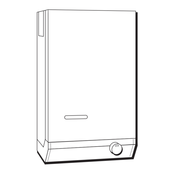
This is a Wall Mounted Fan Assisted Balanced Flue Gas Boiler.
This boiler is for use with Natural Gas (G20) only at 20 mbar and for use in GB & IE.
The Gas Safety (Installation and Use) Regulations 1998.
'' In your own interest, and that of safety, it is law that all gas appliances are installed by competent
persons, in accordance with the above regulations. Failure to install appliances correctly could
lead to prosecution.''
Installation must be in accordance with the Installation & Service Instructions and the rules in
force.
Leave these instructions and the Benchmark Log Book with the user for use on future calls.
40eL - 80eL
The code of practice for the installation,
commissioning & servicing of central heating systems
Profile
TM
Advertisement
Table of Contents

Related Manuals for Potterton Profile 40eL


Summary of Contents for Potterton Profile 40eL
- Page 1 Installation & Service Instructions Profile 40eL - 80eL About the Boiler See inside cover for models covered by these instructions. This is a Wall Mounted Fan Assisted Balanced Flue Gas Boiler. This boiler is for use with Natural Gas (G20) only at 20 mbar and for use in GB & IE.
-
Page 2: Table Of Contents
2. Installation...........13 of the controls cover. Unpack the Boiler and Flue......13 Fixing Template..........13 Potterton is a member of the Benchmark initiative and fully Boiler Mounting Plate........13 supports the aims of the programme. Benchmark has been The Flue............14 introduced to improve the standards of installation and Air/Flue Duct Assembly........14... -
Page 3: Technical Data
Technical Data Boiler model Output kW (Btu/h) 11.72 (40,000) 14.65 (50,000) 17.58 (60,000) 23.45 (80,000) Input kW (Btu/h) 14.42 (49,200) 18.02 (61,500) 21.66 (73,900) 28.88 (98,500) Gas rate m³/h (ft³/h) max 1.34 (47.5) 1.68 (59.4) 2.02 (71.3) 2.69 (95.1) Burner Pressure 12.3 (4.9) 11.5 (4.6) 13.0 (5.2) -
Page 4: Introduction
Introduction Gas Safety (Installation & Use) Regulations 1998. The boilers are for use on Natural Gas (G20) only. This appliance must be installed and serviced by a competent Samples of the Profile gas boilers have been examined by person, in accordance with the above regulations. Advantica Technologies Limited, a United Kingdom Notified Body. -
Page 5: Codes Of Practice
Health & Safety Document No. 635 "The Electrician At Service publication Part 19 - Building and Kitchen Work). If Work Regulations 1989". in doubt advice must be sought from Potterton. Gas Supply The boiler may be installed in any room, although particular... - Page 6 Flow Pipe Return Pipe Fan Mounting WARNING Plate Fan Supply Leads Gravity DHW/ Pump Over-run Thermostat Overheat Capillary Thermostat Capillary Heat Exchanger Air Pressure Pipe Fan Lead & Boiler Overheat Drain Cap Thermostat Capillary Retaining Clip Ignition Electrode Combustion Chamber Pilot Main Burner Thermostat...
-
Page 7: Air Supply
*50 (60) *300 Return (310) Flow *125 (135) Electrical (35) Connections Inside Control Gas Connection *30 (40) R.c½ (½" BSP Female) Model * Note: If pipework is to be run down the back of the boiler, the normal clearance of 28 mm between the rear of the boiler and Dimension wall can be increased to 38 mm if desired by inverting the boiler mounting plate during installation. -
Page 8: Flue Terminal Location
Flue Terminal Location Likely flue positions requiring a flue terminal guard Fig. 4 • Where a horizontal flue is sited less than Horizontal Terminal Position with Minimum Distance (mm) 2 m above a balcony, above ground, or above a flat roof to which people have Fanned Draught Balanced Flue access, a suitable terminal guard must be fitted. -
Page 9: The System
The System Combined Gravity Hot Water, Pumped Central Heating Systems If plastic pipe is used for the central heating circuit there Where a cylinder thermostat and zone valve is used to must be a run of at least 1 m of un-insulated copper pipe control the temperature of the hot water it is recommended from the boiler flow and return connections. - Page 10 Sealed Systems The boiler flow temperature is controlled at approximately Installation 82 °C. The vessel size can now be determined from the The installation must comply with the requirements of information in Table 1 where V = System volume in BS 6798: 1987 and BS 5449: Pt 1.
- Page 11 Water Level Vent Optional Optional 3 Port Zone Valve Valves By-pass balancing valve of Heat Alternative By-pass arrangement using the Exchanger Bathroom Radiator fitted with two locksheild valves Boiler Fig. 5 Cylinder Make up Vent Vessel Optional Optional Pressure 3 Port Zone Gauge Safety...
- Page 12 Cylinder By-pass using bathroom radiator connected into Gravity Circuit and fitted with two lockshield valves to be installed when a Min. Optional zone valve is fitted in Circulating Zone Valve Head 1.2m Gravity Circuit (4ft) Fig. 8 Circulation Pump Selection Model Water Flow Rate Boiler Resistance...
-
Page 13: Installation
2. Installation These instructions assume you have decided on where the boiler will be located and the type of flue system to be Boiler Pack contains: used. Boiler, Literature Pack, Auxiliary pack containing boiler mounting bracket, gas service cock and accessory packs. 2.1. -
Page 14: The Flue
2.4. The Flue Side Flue 1. Measure from outside face of wall to the side of boiler casing reference line (dimension 'x'). 2. Take air/flue duct assembly and measuring from the flanged end mark and cut the outer duct and inner flue duct to dimension 'x' plus PRF0014A 20 mm. -
Page 15: Prepare The Boiler
Flue Elbow Extension Door Flue Elbow Hinge Brackets Flue Outlet Sealing Plate Boiler Main Assembly Connector Securing Screw Combustion Chamber Access Door Front Panel Controls Cover Fig. 14 5. Insert the assembly into the wall sliding the rope Note: If side fluing, loosen the two brass securing sealing ring along the air duct into the flue sealing nuts beneath the flue elbow outlet and remove the collar. -
Page 16: Install The Boiler
2.7. Install the Boiler Air/Flue Duct Assembly Lift the boiler onto its mounting bracket. Locate the studs on the air duct flange through the boiler casing and secure using four wing nuts (accessory pack F). Wing Nuts (4 off) Fig. 16 Position boiler on its mounting bracket so that the sides of the boiler line up with the reference lines ‘C’... - Page 17 When side fluing, slide the elbow extension onto the elbow and ensure that it is pushed Red or Pink Sensing Clear Sensing Tube on fully. Engage the screw from accessory Tube (connect to red indicator) (no kinks in either tube) pack ‘C’...
-
Page 18: Connect System Pipework
22mm Pumped Return Olive 28mm Gravity 28mm Return Injector Disc 28mm 28mm Pumped Return Olive Fig. 20 Gravity Flow Injector Disc Pumped Gravity Flow Return 2.8. Connect System Pipework Connect system pipework to the boiler, compression fittings should be used. Ensure that the flow and return pipes do not rotate during tightening. -
Page 19: Overheat Thermostat Bulb Position
3 Core ETC. incorporate a suitable junction box. This may not be required if a Potterton Electronic Programmer is used as this incorporates a junction box. The principle of wiring is shown Fig. 22 in Fig. -
Page 20: Fitting Side Infill Panels
Following the pump manufacturer’s instructions connect the pump supply wires to terminals marked PUMP L, N, on the boiler terminal block. Route the cable through the plastic bush in the rear of the control box as illustrated in Fig. 24 and secure, using the cable clamp. Route a four core cable through the plastic bush in the rear of the control box and the cable clamp as illustrated in Fig. -
Page 21: Commissioning
When checking for gas soundness open only be carried out by a suitably qualified all windows and doors in the room. personnel. Potterton offer this service on a Extinguish all naked lights, cigarettes, pipes, etc. chargeable basis. Open Vented Systems Gas will flow to the pilot only. - Page 22 Refer to Fault Finding Chart Fig. 31 Pilot Burner Turn the boiler thermostat on and to a high setting and The pilot is pre-set and no adjustment is required. The after a period of time the main burner will light, this can pilot flame envelope should cover the electrode tip and be observed through the sight glass in the front cover of spark earthing strip, see Fig.
- Page 23 Pilot Screw Spacer (For test purposes only) PRF0028A Burner Pressure Seals Adjusting Screw Fig. 26 External Controls Check that any other external control connected in the system, such as clocks and thermostats, control the boiler as required. User’s Instructions A User’s Instructions leaflet is provided with this boiler but the householder must have the operation of the boiler and system explained by the Installer.
- Page 24 Central Heating Switched Live on Combined Gravity Gravity/Fully D.H.W. Pumped C.H. Systems Pumped System Selection Switch Gravity Hot Water (Shown in Fully Permanent Live on Pumped Position) Fully Pumped Systems or Pump Over Run Pump Thermostat Black 4 NO Pump Switched Live on White Fully Pumped Systems...
-
Page 25: To Service The Boiler (S) & Component Replacement (R)
Servicing is best arranged by a contract placed with that the gas rate and main burner pressure are correctly set. Potterton and further details are available from Service If the pilot flame is satisfactory, no further servicing of the Enquires - see back page. -
Page 26: S) Prepare Boiler For Servicing
Preparing the Boiler for Servicing Heat Exchanger Note: Boilers with side or rear flues have a flue elbow A. Working from above and below the heat exchanger fitted to the fluehood. use a suitable brush and remove all deposits from between the fins. -
Page 27: (S) Combustion Chamber Insulation
F. Reconnect gas supply at gas service cock and turn on gas. Spark Gap G. Refit the combustion chamber front panel. 2.5 - 4.0mm A. Carefully clean any deposits from around the fan motor and its supports. B. Very gently clean the fan impellor taking care not to damage the aluminium impellor or dislodge its balance weights. -
Page 28: (R) Gas Control Valve
Removal/Replacement of Boiler Mounted Units 6. Follow the full commissioning procedure as detailed in the Commissioning section of these instructions Gas Control Valve on page 21. This operation is most easily carried out by first removing 4.10 Main Burner the burner and gas control valve assembly as follows:- 1. -
Page 29: R) Combustion Chamber Insulation
5. Unscrew the two hexagonal head screws securing the pilot (and shield on 80) to the main burner and 4.13 Fuse 1 amp remove the pilot assembly, be careful that the pilot injector does not fall out during this operation. 4. -
Page 30: R) Overheat Thermostat
4.16 Overheat Thermostat 13.Remove the split grommet in the base of the boiler and the split grommet in the fan chamber. Feed the 4. Remove door by undoing the two lower fixing screws capillary and bulb through the holes. and lifting door off the two upper hinge brackets. 14.Replacement is the reverse of removal. - Page 31 Intentional Blank Intentional Blank Publication No. 5105703...
-
Page 32: Fault Finding
5. Fault Finding Guide Fig. 31 Fault Finding Publication No. 5105703... -
Page 33: Optional Extras And Accessories
6. Optional Extras Optional Extras Internal Fitment Kit, which is suitable for a maximum wall thickness of 510 mm and where access to the outside wall is impracticable. Pump Cover Kits, located on top of the boiler and designed to conceal the pump, and/or any motorised valves installed above the boiler. -
Page 34: Short List Of Spares
7. Short List Of Spare Parts Fig. 32 Short List Spare Parts Publication No. 5105703... - Page 35 Drg. Ref. G.C. No. Description Part No. 382 453 Pilot and Electrode Assembly 212259 Includes items 2 and 4 381 656 Pilot Injector 402915 357 932 Shear Off Union 402492 382 448 Electrode 402925 337 369 Electrode Lead 407697 248 147 Control Thermostat K36 L1014 907729 395 796...
- Page 36 All goods are sold subject to our standard Conditions of Sale which are available on request. Baxi Potterton Brownedge Road, Bamber Bridge Preston, Lancashire PR5 6SN www.potterton.co.uk...
Need help?
Do you have a question about the Profile 40eL and is the answer not in the manual?
Questions and answers