Table of Contents
Advertisement
Quick Links
Installation & Service Instructions
About the Boiler
About Safety
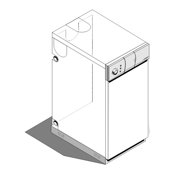
This is a Floor Standing, Horizontally Fired, Automatic Pressure Jet Oil Boiler.
The boiler can be flued conventionaly or with a kit as a balanced flue.
This boiler is for use with Kerosine and for use in GB & IE.
This boiler can be converted for use with Gas Oil (CF only, not 45/50L).
Installation must be in accordance with the Installation & Service Instructions and the rules in
force.
Leave these instructions with the user for use on future calls.
Statesman
45/50L, 50/70L,
70/90L, 90/110L
Advertisement
Table of Contents

Related Manuals for Potterton Statesman 50/70L


Summary of Contents for Potterton Statesman 50/70L
- Page 1 Installation & Service Instructions Statesman 45/50L, 50/70L, 70/90L, 90/110L About the Boiler This is a Floor Standing, Horizontally Fired, Automatic Pressure Jet Oil Boiler. The boiler can be flued conventionaly or with a kit as a balanced flue. This boiler is for use with Kerosine and for use in GB & IE. This boiler can be converted for use with Gas Oil (CF only, not 45/50L).
-
Page 2: Table Of Contents
Contents Section 1 - Technical Data..........4 Health & Safety Information..........4 Control Panel Wiring Diagram........5 Technical Data..............6 Boiler Dimensions & Clearances........7 Flue Layouts..............8 Section 2 - Pre-Installation Requirements....9 Chimneys/Flues............10 Combustion & Ventilation Air Requirements....11 Balanced & Low Level Terminal Clearances....12 Oil Tanks & Layouts............14 Floor Temperatures............16 Section 3 - Installation &... - Page 3 WARNING ! - this is about YOUR safety Safe use of Kerosines and Gas Oils Hazards These fuels give off a flammable vapour when heated even moderately. This vapour ignites easily, burns fiercely and can be explosive. Vapour can flow along at ground level and collect as an explosive mixture in drains, cellars etc. at considerable distances from open containers or spillages.
-
Page 4: Section 1 - Technical Data
1 - Technical Data • The Statesman boilers are horizontally fired, Flue Gas Sampling Point automatic pressure jet boilers. These boilers are intended for use on indirect central heating systems. To aid commissioning, a flue gas sampling point is Their use on direct systems is not recommended. built into the heat exchanger front access door. -
Page 5: Control Panel Wiring Diagram
Statesman Top Flue Knockout Top Casing Side Flue Knockout Thermostat Flue Outlet Flange Pocket Programmer (Optional) Side Flue Knockout Indicator Lights Control Flow Outlet Thermostat Thermostat Pocket Front Access Door Boiler Shell Flue Gas Burner Sampling Air Inlet Side Burner Lead Cover Viewing Window Return Inlet... -
Page 6: Technical Data
Technical Data Model 45/50 50/70 70/90 90/110 Btu/h Btu/h Btu/h Btu/h Maximum Output 51,000 68,000 89,000 110,000 Minimum Output 44,000 51,000 68,000 89,000 Factory Set Output Kerosine 51,000 60,000 17.5 79,000 99,000 Riello Burner Type RDB1 RDB1 RDB1 RDB2 Combustion Head Type Kerosine LD2SH LD2SH... -
Page 7: Boiler Dimensions & Clearances
Boiler Dimension & Clearances Model 45/50 50/70 70/90 90/110 Height Width Depth Centre of Flue from rear Flue Diameter Height between connections Height of bottom connection Distance of connection from wall Return Connections 2 off 1" B.S.P. 1" B.S.P. 1" B.S.P. 1"... -
Page 8: Flue Layouts
Flue Options: Low Level Horizontal High Level Horizontal High Level Vertical Flue Kits 1, 2, 5, & 6 Flue Kits 3, 5, 6, 7, & 8 Flue Kits 3, 4, 5, 6, 9 & 10 Suitable for all Models Suitable for all Models Suitable for all Models Kits 7 &... -
Page 9: Section 2 - Pre-Installation Requirements
These books are available from OFTEC, Century House, 100 High Street, Banstead, Surrey SM7 2NN. Training Potterton have several training centres around the country, for details of courses for oil firing telephone 0845 6007402. OFTEC also hold training courses on oil fired central heating. -
Page 10: Chimneys/Flues
Control of pollution (oil) regulations. • Local water undertakings bye-laws. Chimney Every Potterton boiler has a very high efficiency and care must be taken to ensure that the chimney is suitable. Chimneys may have been already built and completed before a choice of appliance has been made. -
Page 11: Combustion & Ventilation Air Requirements
Internal Flues c) For the satisfactory operation of any draught break or stabilizer which may be fitted. The exposed flue pipe between the boiler flue off-take and the chimney proper (either internally or externally) Air for Combustion must not be of asbestos. Vitreous Cast Iron, Steel or similar materials should be used. -
Page 12: Balanced & Low Level Terminal Clearances
Extract Fans Draught Breaks If the room in which the appliance is located also has an When an appliance with a draught break is fitted in a room extract fan the performance of the appliance must be add 550mm /kW to the free area of the combustion air unaffected when the fan is running with all doors and inlet. - Page 13 Clearances Required Around Balanced and Low Level Discharge Flues Fitted to Oil Fired Boilers Likely flue positions requiring Fig. 8 a flue terminal guard Terminal Position with Minimum Distance (mm) A Directly below an opening, air brick, opening window Where the terminal is within 1 metre of any plastic material, such material should be B Horizontally to an opening, air brick, opening window protected from the effects of combustion...
-
Page 14: Oil Tanks & Layouts
Tank Support Adequate safety may be achieved in a number of ways, for example: Steel tanks are normally supported on masonry piers. These have to maintain the tank at a sufficient height to a) Protecting the tank by a physical barrier or isolating enable access to be gained for painting. - Page 15 Storage Requirements and Tank Sizes end of the vent is fitted with a return bend and an open wire mesh balloon. Tanks are available in a wide variety of sizes and capacities. For boilers of up to 13 kW (45,000 Btu/h) A mushroom type vent may be fitted provided its free tanks with a capacity of 1200 litres (250 gallons) are area is at least equal to the cross sectional area of the...
-
Page 16: Floor Temperatures
appliances with pressure jet burners by means of the building in the event of a fire starting up within the a single pipe need to be positioned so that they will boiler. apply the 300 mm minimum required head of oil to The valve should be located just outside the building the burner when the fuel level is at its lowest point. - Page 17 Single Pipe Supply System Max. Oil Level 4 metres Above Burner Fire Valve Shut Off Sensor Valve Filter Fire Valve Max. Head 4m Pump Fire Valve De Aeration Sensor Device Fire Valve Oil Tank Below or Level Isolating with Burner Valve Oil Supply Pump...
-
Page 18: Section 3 - Installation & Commissioning
3 - Installation & Commissioning Low Level Horizontal - Kits 7, 8 & 12 Low Level Horizontal - Kits 1 & 2 With Extensions With Extensions Dress Plate (Inner Wall) Dress Plate (Outer Wall) Kit 5 Kits 7 & 8 950mm Kits 7 &... -
Page 19: Conventional Flue
Installation & Commissioning It is possible to install the boiler without removing the casing sides but care should be taken not to damage the panels when connecting the water pipes. Fitting a Balanced Flue Refer to the Instructions supplied with the flue. Fitting a Conventional Flue Local Building Regulations and Bye Laws should be consulted for details of the chimney, use a 135°... -
Page 20: Fuel Pipes
Wiring Diagrams: Refer to wiring diagrams in Section 1 of these Instructions. The mains inlet plug is provided in the bag of fittings supplied. Control Box To wire in external controls, open the door on the Assembly right hand side of the facia panel, to expose a Remove blanking plate . - Page 21 Fig. 15 Fig. 16 Installation & Commissioning Part No. 5105707...
-
Page 22: Water Connections
An Isolation Valve should be placed on the tank side Retarders of the filter, so that the oil supply can be isolated when servicing is required. There is an access door above the burner behind the heat shield, remove and check the retarders are sound Ensure that the filter is positioned correctly and that it and in position. - Page 23 Fig. 23 Remove the Air Tube Refit the Air Tube Inspection Hatch Door Bulkhead Bracket Heat Shield 45/70 Models Shown Fig. 18 Installation & Commissioning Part No. 5105707...
-
Page 24: Commissioning
Commissioning 5. Check that the water system is filled and vented. It is strongly recommended that the boiler/burner is 6. Check that all controls are calling for heat. commissioned by a qualified technician, preferably OFTEC trained and registered. 7. Switch on electricity supply. Burner 8. - Page 25 11. Switch off the boiler, remove the pressure gauge and re-fit the plug. 12. Re-fit the burner cover and boiler casing panels, 13. Switch the boiler on. Allow the burner to run for about 15 minutes. The flue gas sampling point should be used whilst adjusting the air to give clean combustion.
- Page 26 Models: 50/70, 70/90 & Remove The 3 Retarders, Examine For Model: 45/50 Damage, Replace if Necessary 90/110 has 6 Retarders Front Access Door Lift Out The Plate With This Hole Baffle Plate For Model Boiler Shell 50/70 & 70/90 Remove The Baffle Examine The Plate &...
-
Page 27: Section 4 - Servicing & Maintenance
4 - Servicing & Maintenance • If the balanced flue is dismantled for any reason and • Examine interior of boiler and if necessary clean. the flue seals disturbed, new seals must be fitted. Remove any loose debris from the combustion Refer to the Parts Catalogue for part numbers. -
Page 28: Replacement Of Parts
• Clean flue and chimney. Sight • Clean all boiler internal surfaces. Gauge Also, Isolating • De-sludge the fuel tank(s) Valve There should be a sludge valve fitted to the tank(s). • Replace/clean cartridge in main filter If a paper microbic cartridge has been in service for more than one heating season, a replacement should be fitted. -
Page 29: Limit Thermostat
Replacement of Thermostats 1. Remove the front cover. 2. Pull off the temperature control knob. 3. If a clock is fitted un-clip from the facia and disconnect the plug at the back. 4. Remove the facia retaining screws at the base Lift Off The Remove of the facia. -
Page 30: Section 5 - Fault Finding
5 - Fault Finding SYMPTOM CHECK LIST ACTION Burner Does Not 1. Mains switched on Switch on Start, Motor Does 2. Fuse in switch Fit a fuse Not Run 3. Fuse blown Replace fuse 4. All external controls call for heat Set to call for heat 5. -
Page 31: Burner Starts, No Flame But Oil To Burner
SYMPTOM CHECK FOR ACTION Burner Starts, 1. Signs of fuel in boiler Check as for 2 to 8 below No Flame But 2. Correct combustion head settings Set correctly refer to Burner Oil To Burner Instructions 3. Electrodes clean and not damaged Clean 4. -
Page 32: Flame Established But Not Maintained
SYMPTOM CHECK FOR ACTION Flame Established 1. Air in fuel line Check for joints for increases of air rectify as necessary, bleed burner But Not and restart Maintained 2. Combustion settings incorrect Adjust settings and confirm by flue gas analysis 3. -
Page 33: Other Problems
SYMPTOM POSSIBLE CAUSE ACTION 13. Bad oil cut off Bleed air from pump or replace pump assembly 14. Dirt collecting on fan Remove burner and clean 15. Combustion products leaking Check all joints, replace suspect seals SYMPTOM POSSIBLE CAUSE ACTION 1. -
Page 34: Section 6 - Spare Parts
6 - Short Spares Drg. Description Model - see key Makers Part Ref. Number Boiler thermostat A, B, C, D 26009018 Thermostat knob A, B, C, D 26002014 Limit thermostat A, B, C, D 26009097 Mains inlet plug A, B, C, D 26009004 Retarder A, B... -
Page 35: Section 7 - Flue Kit Options
7 - Flue Kit Options Dress Plate KIT 1 Horizontal Low Level Telescopic Fasteners Pack Instructions (Inner Wall) 4 - wood screws (Short Wall) 100 - 275mm 4 - wall plugs Inner Seal Outer Seal Dress Plate (Outer Wall) Gasket KIT 2 Horizontal Low Level Telescopic Fasteners Pack... - Page 36 All goods are sold subject to our standard Conditions of Sale which are available on request. Baxi Potterton Brownedge Road, Bamber Bridge Preston, Lancashire PR5 6SN www.potterton.co.uk...
Need help?
Do you have a question about the Statesman 50/70L and is the answer not in the manual?
Questions and answers