Table of Contents
Advertisement
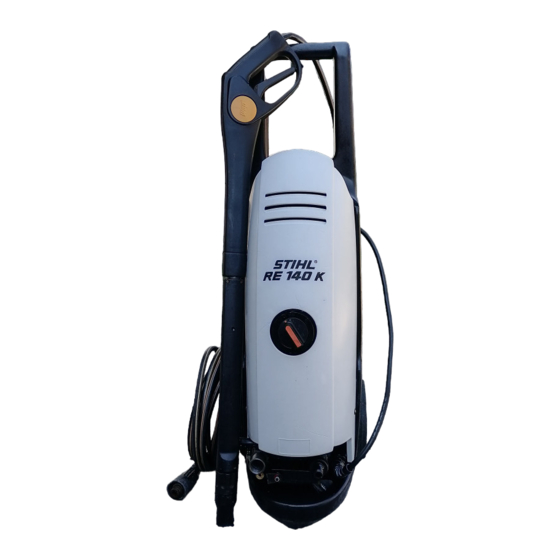
RE 140 K, 160 K
CONTENTS
1.
1.1
2.
3.
3.1
3.2
3.3
3.4
3.5
4.
4.1
4.2
5.
5.1
Removing /
5.2
Removing /
installing the motor /
5.3
6.
6.1
6.2
the control piston
6.3
Setting the pressure
6.4
6.5
6.6
7.
7.1
7.2
7.3
RE 140 K, 160 K
2
7.4
2
7.5
Disassembly /
assembly of
2
pump piston
7.6
Replacing
and oil seals
3
7.7
3
3
8.
3
3
8.1
4
8.2
9.
5
9.1
5
9.2
7
9.2.1
9.2.2
8
9.2.3
9.2.4
9.2.5
8
10.
8
9
10.1
10.2
9
11.
9
10
12.
11
12
12.1
12
12.2
Service tools
13
14
14
14
14
15
15
16
17
18
18
21
23
23
24
24
25
25
26
27
27
28
28
30
31
31
31
© 2000, Andreas Stihl AG & Co., Waiblingen
1
Advertisement
Table of Contents


Need help?
Do you have a question about the RE 140 K and is the answer not in the manual?
Questions and answers