Advertisement
Advertisement
Table of Contents

Subscribe to Our Youtube Channel
Related Manuals for Nordmende HCI90FL


Summary of Contents for Nordmende HCI90FL
- Page 1 HCI90FL INDUCTION HOB INSTALLATION AND OPERATING INSTRUCTIONS...
- Page 2 PART 2 SAFETY WARNINGS READ THESE INSTRUCTIONS CAREFULLY AND COMPLETELY BEFORE USING YOUR APPLIANCE, AND KEEP IT IN A CONVENIENT PLACE FOR REFERENCE WHEN NECESSARY. THIS MANUAL IS PREPARED FOR MORE THAN ONE MODEL IN COMMON. YOUR APPLIANCE MAY NOT HAVE SOME OF THE FEATURES THAT ARE EXPLAINED IN THIS MANUAL. PAY ATTENTION TO THE EXPRESSIONS THAT HAVE FIGURES, WHILE YOU ARE READING THE OPERATING MANUAL.
- Page 3 - For induction hobs, after use, switch off the hob element by its control and do not rely on the pan detector. - For hobs incorporating a lid, any spillage should be removed from the lid before opening. And also the hob surface should be allowed to cool before closing the lid.
- Page 4 During usage - Do not put flammable or combustible materials, in or near the appliance when it is operating. - Do not leave the cooker while cooking with solid or liquid oils. They may catch fire on condition of extreme heating. Never pour water on to flames that are caused by oil. Cover the saucepan or frypan with its cover in order to choke the flame that has occured in this case and turn the cooker off.
-
Page 5: Description Of The Appliance
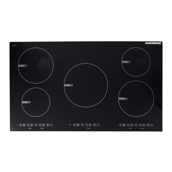
DESCRIPTION OF THE APPLIANCE Dear Customer, Please read the instructions in this user guide before using the hob and keep it for future reference. Cooking Surface for 5 heater:... - Page 6 Control Panel for 2 heater : Timer Key Lock Display Indicator Heater Boost On/Off Timer Lock Display Smart Pause Decrease Increase heat setting heat setting Decrease Increase front front heat setting heat setting back back Control Panel for 1 heater : Timer Key Lock Display...
-
Page 7: Operation Of The Appliance
OPERATION OF THE APPLIANCE Use the induction cooking zones with suitable cookware. After mains voltage is applied, all displays are come on for a moment. When this time is over, the hob is in the stand-by mode and it is ready for operation. The hob is controlled with electronic sensors which are operated by touching the related sensors. - Page 8 Switching all cooking-zones off: To turn all the cooking zones off at once, touch the key. In the stand-by mode, an "H" appears on all cooking zones which are hot. Residual heat indicator: Residual heat indicator indicates that the glass ceramic has a dangerous touch temperature in the circumference of a cooking zone.
-
Page 9: Heat Setting
Safety switch off function: Every cooking zone will be switched off after a defined maximum operation time if the heat setting is not modified. Every change in the cooking zone puts back the maximum operation time to the initial value of the operating time limitation. The maximum operation time depends on the selected temperature level. - Page 10 Timer function : The timer function is realized in two versions: Minute minder timer (1..99 min): The minute minder timer can be operated if the cooking zones are switched off. The timer display shows "00" with a blinking dot. Touch the timer setting key to increase the time or touch to decrease the time.
- Page 11 When the timer has run down, a signal sounds and the timer display shows "00" statically, the assigned cooking zone timer LED blinks. The programmed cooking zone will be switched off and the "H" will be displayed if the cooking zone is hot. The sound signal and the blinking of the timer LED will be stopped automatically after 30 seconds and/or by operating any key.
-
Page 12: Hints And Tips
HINTS AND TIPS Cookware · Use thick, flat, smooth bottomed cookwares that are the same diameter as the element. This will help reduce cooking times. · Cookware made of steel, enamelled steel, cast iron and stainless steel (if appropriately abelled by the manufacturer) will give you the best results. -
Page 13: Examples Of Cooking Applications
Examples of cooking applications The information given in the following table is for guidance only. Use for Settings Element off 1 - 3 Delicate warming 4 - 5 Gentle simmering, slow warming Reheating and rapid simmering 6 -7 Boiling, saute and searing Maximum heat Boost function Cleaning tips... -
Page 14: Installation Of The Appliance
INSTALLATION OF THE APPLIANCE WARNING: The electrical connection of this hob should be carried out by a qualified electrician, according to the instructions in this guide and in compliance with the current regulations. In the event of any damage that occurs as a result of improper connection or installation, the warranty will not be valid. This appliance must be earthed. - Page 15 · Apply the one-sided self-adhesive sealing tape supplied all the way round the lower glass edge of the cooking surface along the outer edge of the glass ceramic panel. Do not stretch it. · Screw the 4 worktop mounting brackets on the side walls of product. worktop mounting bracket ·...
- Page 16 Making an electrical connection Before making a connection, check that: · The mains voltage is the same as that quoted on the rating plate which is situated at the back of your hob. · The circuit can support the appliance load (see the rating plate). ·...
- Page 17 Electrical connection diagram 3x4 mm² 220 V~ 5x1,5 mm² 380 V~ 3x4 mm² 230 V~ 5x1,5 mm² 400 V~ 3x4 mm² 240 V~ 5x1,5 mm² 415 V~ For the induction hob, the cable must be H05VV-F 3X4 mm² 60227 IEC 53 ••. You will find the connection diagram shown on the bottom of your appliance.
- Page 18 ERROR CODES If there is an error, error code will be showed at heater displays. E1 : Cooling Fan is disabled, call authorized service agents. wait E3 : Supply coltage is over than rated values, turn the hob off by touching until “H”...
- Page 19 The symbol on the product or on its packaging indicates that this product may not be treated as household waste. Instead it shall be handed over to the applicable collection point for the recycling of electrical and electronic equipment. By ensuring this product is disposed of correctly, you will help prevent potential negative consequences for the environment and human health, which could otherwise be caused by inappropriate waste handling of this product.
Need help?
Do you have a question about the HCI90FL and is the answer not in the manual?
Questions and answers