Table of Contents
Advertisement
Advertisement
Table of Contents

Related Manuals for Elation ACL 360i


Summary of Contents for Elation ACL 360i
- Page 1 ACL 360I™ user manual ...
- Page 2 Elation Professional USA | 6122 S. Eastern Ave. | Los Angeles, CA. 90040 323-582-3322 | 323-832-9142 fax | www.elationlighting.com | info@elationlighting.com Elation Professional B.V.
-
Page 3: Table Of Contents
C O N T E N T S General Information Warranty Safety Instructions General Guidelines Fixture Overview Frost Lens Installation Fixture Installation Fixture Menu DMX Channel Functions And Values Error Codes Cleaning and Maintenance Technical Specifications Optional Accessories ACL 360I™ User Manual... -
Page 4: General Information
Please do not discard the shipping carton in the trash. Please recycle whenever possible. BOX CONTENTS (1) 10 Degree Frost Lens (1) 45 Degree Frost Lens (1) Omega Bracket (1) powerCON Cable ACL 360I™ User Manual... - Page 5 You may also visit us on the web at www.elationlighting.com any comments or suggestions. For service related issue please contact Elation Professional®. ELATION SERVICE USA - Monday - Friday 8:00am to 5:00pm PST...
-
Page 6: Warranty
No accessories should be shipped with the product. If any accessories are shipped with the product, Elation Professional® shall have no liability what so ever for loss and/or or damage to any such accessories, nor for the safe return thereof. -
Page 7: Safety Instructions
Do not operate this fixture if the power cord has become frayed, crimped and/or damaged. If the power cord is damaged, replace it immediately with a new one of similar power rating. ACL 360I™ User Manual... -
Page 8: General Guidelines
15 minutes for the fixture to cool down before replacing or serving. L E D L I F E The average LED Life (hours) may vary depending on several factors including but not limited to: Environmental Conditions, Power/Voltage, Usage Patterns (On-Off Cycling), Control and Dimming. ACL 360I™ User Manual... -
Page 9: Fixture Overview
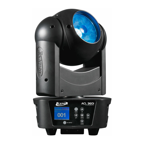
F I X T U R E O V E R V I E W LCD Control Display Fuse DC Switch NET IN/OUT (RJ45 Ethernet) UP, DOWN, LEFT, RIGHT, ENTER Buttons 5pin DMX IN/OUT MODE Button powerCON OUT powerCON IN ACL 360I™ User Manual... -
Page 10: Frost Lens Installation
The fixture includes two FROST Lens options (10° and 45°) which can be easily installed unto the fixture’s head. See below for installation instructions. 1. Place fixture on a flat surface and remove (2) screws of the lens cover assembly. 2. Remove the lens cover, ACL 360I™ User Manual... - Page 11 F R O S T L E N S I N S T A L L A T I O N [ c o n t i n u e d ] 3. Gently place the desired FROST Lens on top and in the middle of the LED reflector. ACL 360I™ User Manual...
- Page 12 F R O S T L E N S I N S T A L L A T I O N [ c o n t i n u e d ] 4. Replace the lens cover and install / tighten the (2) screws securely. ACL 360I™ User Manual...
-
Page 13: Fixture Installation
10 times the weight of the fixture. Fixture installation must always be secured with a secondary safety attachment, such as an appropriate safety cable. Never stand directly below the device when mounting, removing or servicing. ACL 360I™ User Manual... - Page 14 Fixture is fully operational in the specific mounting positions as illustrated below. S A F E T Y C A B L E ALWAYS USE A SAFETY CABLE WHENEVER INSTALLING THIS FIXTURE IN A SUSPENDED ENVIRONMENT TO ENSURE THE FIXTURE WILL NOT DROP IF THE CLAMP FAILS. ACL 360I™ User Manual...
- Page 15 Bracket using a M10 screw fitted through the center hole of the Omega Bracket. Be sure to attach an appropriate Safety Cable (not included) to the fixture using the safety cable rigging point integrated in the base assembly. ACL 360I™ User Manual...
-
Page 16: Fixture Menu
OFF automatically about 1 minute from the last button press. INFORMATION DISPLAYED DURING INITIAL POWER ON When the fixture is initially powered ON, the display shows the following information: Software Update Motor Reset Please Wait... Please Wait... ACL 360I™ User Manual... - Page 17 Temperature in Fixture Head XXX C° / F ° Error Info Error Record 1 ~ Error Record 10 Display Error Messages Model. Info ACL360i Display Model Name 1U01: ≥V1.07 Software Version 2U01: ≥V1.07 Software Versions 3U01: ≥V1.07 ACL 360I™ User Manual...
- Page 18 (8), and then set Channel 3 to a value of (164). (256+164=420) 5. After setting Channel 3 to the desired DMX address value, wait for approximately 20 seconds for the fixture to complete the address reset function. ACL 360I™ User Manual...
- Page 19 Because calibration is an extremely delicate procedure, instructions on performing this action are left out of this manual. For a first time calibrator, please contact our customer support team for step-by-step instructions. ACL 360I™ User Manual...
-
Page 20: Dmx Channel Functions And Values
128-189 TILT Clockwise from FAST to SLOW 190-193 NO Rotation 194-255 TILT Counter-Clockwise from SLOW to FAST 0-255 0 to 100% GREEN 0-255 0 to 100% BLUE 0-255 0 to 100% WHITE 0-255 0 to 100% ACL 360I™ User Manual... - Page 21 93-96 COLOR PRESET 24 97-100 COLOR PRESET 25 101-104 COLOR PRESET 26 105-108 COLOR PRESET 27 109-112 COLOR PRESET 28 113-116 COLOR PRESET 29 117-120 COLOR PRESET 30 121-124 COLOR PRESET 31 125-128 COLOR PRESET 32 ACL 360I™ User Manual...
- Page 22 COLOR PRESET 64 FLASH / STROBE 0-31 LED OFF 32-63 LED ON 64-95 Strobe Effect SLOW to FAST 96-127 LED ON 128-159 Pulse Effect in Sequences 160-223 Random Strobe Effect SLOW to FAST 224-255 LED ON ACL 360I™ User Manual...
- Page 23 0-255 0-100% DIMMING CURVE MODES 0-20 STANDARD 21-40 STAGE 41-60 61-80 ARCHITECTURAL 81-100 THEATRE 101-255 Default to Unit Setting PAN / TILT MOVEMENT SPEED 0-225 MAX to MIN SPEED 226-235 Blackout By Movement 236-255 NO FUNCTION ACL 360I™ User Manual...
- Page 24 Internal Program 1 (scene1~8) 120-139 Internal Program 2 (scene9~16) 140-159 Internal Program 3 (scene17~24) 160-179 Internal Program 4 (scene25~32) 180-199 Internal Program 5 (scene33~40) 200-219 Internal Program 6 (scene41~48) 220-239 Internal Program 7 (scene49~56) 240-255 NO FUNCTION ACL 360I™ User Manual...
- Page 25 0 to 100% SHUTTER / STROBE 0-31 LED OFF 32-63 LED ON 64-95 Strobe Effect SLOW to FAST 96-127 LED ON 128-159 Pulse Effect in Sequences 160-223 Random Strobe Effect SLOW to FAST 224-255 LED ON ACL 360I™ User Manual...
- Page 26 50-54 SALMON 55-59 TURQUOISE 60-64 LIGHT GREEN 65-69 STEEL BLUE 70-74 ORANGE 75-79 STRAW 80-84 PALE LAVENDER 85-89 PINK 90-94 95-99 GREEN 100-104 BLUE 105-109 WHITE 110-255 RESERVED COLOR PRESETS DIMMER 0-255 Intensity 100% to 0% ACL 360I™ User Manual...
- Page 27 Internal Program 3 (scene17~24 of EEPROM) 160-179 Internal Program 4 (scene25~32 of EEPROM) 180-199 Internal Program 5 (scene33~40 of EEPROM) 200-219 Internal Program 6 (scene41~48 of EEPROM) 220-239 Internal Program 7 (scene49~56 of EEPROM) 240-255 NO FUNCTION ACL 360I™ User Manual...
-
Page 28: Error Codes
(sensor failed or magnet is missing) or there is a motor PAN Er failure (defective motor or a defective motor IC drive on the main PCB). This error may also be displayed if the head/yoke was blocked during a reset function. ACL 360I™ User Manual... -
Page 29: Cleaning And Maintenance
Regular inspections are recommended to insure proper function and extended life. There are no user serviceable parts inside this fixture, please refer all other service issues to an authorized Elation service technician. Should you need any spare parts, please order genuine parts from your local Elation dealer. -
Page 30: Technical Specifications
110W Max Power Consumption 5F to 113°F (-15°C to 45°C) APPROVALS / RATINGS CE | IP30 Please Note: Specifications and improvements in the design of this unit and this manual are subject to change without any prior written notice. ACL 360I™ User Manual... - Page 31 WHITE LEDs 11,140 1,035 5,437 2,708 1,969 FULL ON 6.6 ft 9.8 ft 13.1 ft 16.4 ft 45° FROST 0.88 1.33 1.77 2.21 Diameter RED LEDs GREEN LEDs BLUE LEDs 1,032 WHITE LEDs 1,649 FULL ON ACL 360I™ User Manual...
-
Page 32: Dimensional Drawings
. e l a t i o n l i g h t i n g . c o m DIMENSIONAL DRAWINGS Please Note: Specifications and improvements in the design of this unit and this manual are subject to change without any prior written notice. ACL 360I™ User Manual... -
Page 33: Optional Accessories
O P T I O N A L A C C E S S O R I E S ORDER CODE ITEM TRIGGER CLAMP Heavy Duty Wrap Around Hook Style Clamp * * * pending * * * ACL 360i Road Case CAT005 5’ (1.5m) CAT6 EtherCON Cable PLC3 3 ft. (1m) PowerCON PRO Link Cable AC5PDMX5PRO 5 ft.
Need help?
Do you have a question about the ACL 360i and is the answer not in the manual?
Questions and answers