Makita EM2650UH Technical Information
Hide thumbs
Also See for EM2650UH:
- Original instruction manual (256 pages) ,
- Instruction manual (188 pages) ,
- Parts breakdown (8 pages)
Table of Contents
Advertisement
Quick Links
T
ECHNICAL INFORMATION
Models No.
Description
C
ONCEPT AND MAIN APPLICATIONS
These four 25.4mL Petrol Brushcutters have been developed as
the successor models of
equipped with 24.5mL 4-stroke engine.
Their main feature is the multi-position engine lubrication system.
This unique system enables the engine to be inclined to any angle
even during continuous operation with no emission of white smoke
and smell of burning engine oil for wider application range of the
brushcutters.
EM2651UH and EM2651LH additionally feature rapid start.
EM2650UH and EM2651UH are Bike handle models.
EM2650LH and EM2651LH are Loop handle models.
S
pecification
Specifications
Type
Displacement: mL (cu.in.)
Engine
Fuel
Max. output: kW
Max. torque: N.m
No load speed
: min.
*2
Engine oil
Carburetor
Starting system
Fuel tank capacity: L (oz)
Spindle thread size
Primer pump
Clutch
Handle style
Rapid start
Waist cushion
Net weight
: kg (lbs)
*4
*1 Brazil: 25E gasoline
*2 No load speed of the cutting tool
*3 Of asymmetrical design
*4 Dry weight, without universal guard, cutting tool and shoulder harness
S
tandard equipment
Cutting tool ......................................................................................... 1
Universal guard (=Protector) ............................................................. 1
Shoulder harness with double shoulder straps ................................... 1 (for EM2650UH, EM2651UH)
Shoulder harness with single shoulder strap ...................................... 1 (for EM2650LH, EM2651LH)
Socket wrench .................................................................................... 1
Hex wrench (for M4) ......................................................................... 1
Hex wrench (for M5) ......................................................................... 1
Wire clamp (for tying cables) ............................................................. 2 (for EM2650UH)
Oil bottle without oil or Oil bottle containing 80mL engine oil ......... 1
Accessory bag .................................................................................... 1
Note: The standard equipment for the tool shown above may vary by country.
O
ptional accessories
Metal blades [230mm (9") 3-tooth, 4-tooth, 8-tooth], Nylon cutting heads [Ultra auto 4, Bump & feed 4,
Bump & feed Z5], Gardening attachments (for EM2650LH, EM2651LH)
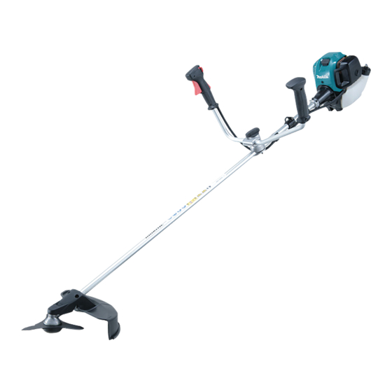
EM2650UH/ EM2650LH,
EM2651UH/ EM2651LH
Petrol Brushcutter
and
EBH252U/EBH252L
EBH253U/EBH253L
Model
EM2650UH
rpm
7370
-1 =
Bike handle
No
No
5.5 (12.1)
EM2650UH
EM2651UH
Model No.
Length (L)
Width (W)
Height (H)
EM2650LH
4-stroke
25.4 (1.5)
Straight unleaded gasoline
0.77 [at 7,000 min-
1.1 [at 5,500 min-
6,630
SAE10W-30 oil
in the Class SF or higher of API Classification
Diaphragm
Recoil starter, with mechanical decompression
0.6 (20.3)
M10, Left-handed
Yes
Yes
Loop handle
*3
No
No
5.1 (11.2)
PRODUCT
W
W
H
L
L
EM2650LH
EM2651LH
Dimensions: mm (")
EM2650UH
EM2650LH
EM2651UH
EM2651LH
1,765 (69-1/2)
620 (24-3/8)
330 (13)
474 (18-5/8)
264 (10-3/8)
EM2651UH
EM2651LH
*1
]
1
]
1
7370
6,630
Bike handle
Loop handle
*3
Yes
Yes
Yes
No
5.6 (12.3)
5.2 (11.4)
P 1/ 14
H
Advertisement
Table of Contents

Related Manuals for Makita EM2650UH


Summary of Contents for Makita EM2650UH
- Page 1 Cutting tool ..................1 Universal guard (=Protector) ............. 1 Shoulder harness with double shoulder straps ........1 (for EM2650UH, EM2651UH) Shoulder harness with single shoulder strap ........1 (for EM2650LH, EM2651LH) Socket wrench ..................1 Hex wrench (for M4) ................. 1 Hex wrench (for M5) .................
-
Page 2: Necessary Repairing Tools
(2) replace Gasket with the new one. [3] LUBRICANT / ADHESIVE APPLICATION Apply Makita grease N No.2 to Spiral spring in Recoil starter and the spline ends of Shaft. When cleaning the inside of Gear case, apply 40g Makita grease N No.2 into Gear case. - Page 3 P 3/ 14 epair [4] DISASSEMBLY/ASSEMBLY [4]-2. Engine and Shaft Fig. 1 DISASSEMBLING (1) Disconnect lead wire and grounding wire by removing each connector after removal of Air cleaner cover. (Fig. 1) (2) Remove Control cable from Insulator by loosening the adjust screw (Fig. 2) then by the disconnecting inner cable from Swivel of Carburetor.
- Page 4 P 4/ 14 epair [4] DISASSEMBLY/ASSEMBLY [4]-3. Shaft pipe complete DISASSEMBLING (1) Loosen two M6x30 Hex. socket head bolt (2pcs.) and remove Protector with Protector extension attached. (Fig. 7) (2) Enlarge the space between the side wall of Protector cover and M5x14 Hex socket head bolt, and remove Protector cover from Shaft pipe complete.
- Page 5 P 5/ 14 epair [4] DISASSEMBLY/ASSEMBLY [4]-4. Gear case assembly DISASSEMBLING (1) According to the clause of [4]-3, Remove Gear case assembly. (2) Remove M8x10 + Hex bolt that is the stopper of Grease inlet on Gear case set. (Fig. 13) (3) Remove Retaining ring R-24 with 1R006.
- Page 6 P 6/ 14 epair [4] DISASSEMBLY/ASSEMBLY [4]-5. Clutch Fig. 22 DISASSEMBLING Note: (1) Clutch can be easily removed with Impact driver 13mm Socket bit M6x25 shoulder without holding the piston. hex bolt (2pcs.) (2) Do not remove Spark plug as compressed air resistance has to be used for the disassembling.
- Page 7 P 7/ 14 epair [4] DISASSEMBLY/ASSEMBLY [4]-7. Ignition Fig. 28 CHECK OF PLUG CAP Plug cap (1) Remove Plug cap from Spark plug, then detect the continuity between Plug cap spring in Plug cap and Earth terminal of Ignition coil. It is the normal condition when Tester shows 2.0kΩ±0.5kΩ.
- Page 8 P 8/ 14 epair [4] DISASSEMBLY/ASSEMBLY [4]-8. Flywheel DISASSEMBLING Note: • Flywheel can be easily removed without holding the piston. • Do not remove Spark plug as compressed air resistance has to be used for the disassembling. • Plug cap with Plug cap spring has to be removed from Spark plug to prevent Engine from running. (Fig. 29) (1) Turn M8 Flange nut in the center of Flywheel counterclockwise using Cordless impact driver with 13mm Socket bit.
-
Page 9: Recoil Starter
Reel. (Fig. 38) Curved end of Spiral spring (2) Apply a little amount of Makita grease N No.2 to the spring. (Outer side) (3) Make a knot on the new rope end and pass it through Reel and Starter case, Curved end of Spiral then, connect the other end to Starter knob. - Page 10 P 10/ 14 epair [4] DISASSEMBLY/ASSEMBLY [4]-10. Carburetor Fig. 44 Fig. 45 DISASSEMBLING Air cleaner M5x60 Hex. socket button (1) Remove Cleaner cover assembly. (Fig. 44) element head bolts are completely (2) Remove Air cleaner element. (Fig. 45) removed. (3) Remove two M5x60 Hex. socket head bolts for fastening Carburetor and Cleaner plate assembly to Insulator.
- Page 11 P 11/ 14 epair [4] DISASSEMBLY/ASSEMBLY [4]-10. Carburetor (cont.) ASSEMBLING Carefully assemble each part in right direction and order. Fig. 50 TEST OF AIRTIGHT STRUCTURE (Nipple to connect yellow tube of Tank) Connect 1R127 to the nipple of Carburetor as drawn in Fig. 50. 1R127 Give air pressure from 1R127 and check if the pressure gauge indicates 0.05Mpa for around 10 seconds, then, there is no problem with...
-
Page 12: Maintenance
P 12/ 14 epair [4] DISASSEMBLY/ASSEMBLY [4]-13. Spark arrester (Only for some countries, i.e., having dry atmospheres at high temperature) MAINTENANCE Fig. 56 (1) Remove Cylinder cover. (2) Remove Exhaust Muffler. Spark arrester (3) Remove Spark arrester from Exhaust muffler(Fig. 56). Sweep it off if dirt or soot is on Spark arrester. - Page 13 (1) Piston can be assembled in either direction. Apply Makita grease N No. 2 to the needle bearing of Crank shaft assembly in advance. (2) Insert Piston pin through Piston and Crank shaft, and fix it with Clips by using an awl (Clip has no direction).
-
Page 14: Fastening Torque
P 14/ 14 epair [4] DISASSEMBLY/ASSEMBLY [4]-14. Engine block (cont.) ASSEMBLING (6) Adjust the valve clearance as follows: • Align the marking on Flywheel with the marking on Ignition coil. (Fig. 62) • Align the marking on Cam gear assembly with the marking on Cylinder block. (Fig. 63) •...
Need help?
Do you have a question about the EM2650UH and is the answer not in the manual?
Questions and answers