Nobles SPEED SCRUB RIDER Operator's Manual
Rider- scrubber
Hide thumbs
Also See for SPEED SCRUB RIDER:
- Specifications (2 pages) ,
- Brochure (3 pages) ,
- Operator's manual (53 pages)
Table of Contents
Advertisement
The Safe Scrubbing Alternativer
Quick-Train
Controls
t
Hygenic
Fully Cleanable Tanks
TennantTrue
Parts
IRIS
a Tennant Technology
For the latest Parts manuals and other
language Operator manuals, visit:
www.nobles.com/manuals
R
SPEED SCRUB RIDER
OPERATOR MANUAL
R
RIDER- SCRUBBER
331140
Rev. 08 (10-2015)
*331140*
Advertisement
Table of Contents
Troubleshooting

Related Manuals for Nobles SPEED SCRUB RIDER


Summary of Contents for Nobles SPEED SCRUB RIDER
- Page 1 SPEED SCRUB RIDER RIDER- SCRUBBER OPERATOR MANUAL The Safe Scrubbing Alternativer Quick-Train Controls Hygenic Fully Cleanable Tanks TennantTrue Parts IRIS a Tennant Technology 331140 For the latest Parts manuals and other language Operator manuals, visit: Rev. 08 (10-2015) www.nobles.com/manuals...
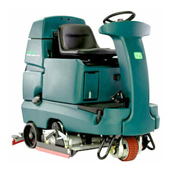
- Page 2 Installation Date - INTENDED USE The Speed Scrub Rider is an industrial/commercial rider machine designed to wet scrub both rough and smooth hard surfaces (concrete, tile, stone, synthetic, etc). Typical applications include schools, hospitals / health care facilities, office buildings, and retail centers. Do not use this machine on soil, grass, artificial turf, or carpeted surfaces. This machine is intended for indoor use only.
-
Page 3: Table Of Contents
CONTENTS CONTENTS Page Page Safety Precautions ..... . . Battery Select Mode ....Important Safety Instructions . -
Page 4: Safety Precautions
SAFETY PRECAUTIONS IMPORTANT SAFETY INSTRUCTIONS - SAVE THESE INSTRUCTIONS The following symbols are used throughout this FOR SAFETY: manual as indicated in the descriptions: 1. Do not operate machine: - Unless trained and authorized. WARNING: To warn of hazards or - Unless operator manual is read and unsafe practices that could result in understood. - Page 5 SAFETY PRECAUTIONS 4. Before leaving or servicing machine: 6. When loading/unloading machine - Stop on level surface. onto/off truck or trailer. - Turn off machine and remove key. - Drain tanks before loading machine. - Lower scrub head and squeegee 5.
- Page 6 SAFETY PRECAUTIONS The safety labels appear on the machine in the locations indicated. If these or any label becomes damaged or illegible, install a new label in its place. WARNING LABEL - WARNING LABEL - Flammable Batteries emit hydrogen materials can cause explosion gas.
-
Page 7: Operation
OPERATION OPERATION MACHINE COMPONENTS A. Recovery tank drain hose M. Solution tank drain hose B. Recovery tank cover N. Squeegee hose C. Recovery tank O. Front solution tank cover D. Operator seat P. Hour meter E. Batteries Q. Circuit breakers F. -
Page 8: Controls And Instruments
OPERATION CONTROLS AND INSTRUMENTS ec- H2O Model A. Solution tank empty indicator B. Recovery tank full indicator C. Battery charge level indicators D. Fault indicator E. Emergency Stop Button F. Directional switch G. Horn button H. On/Off key switch I. One Step scrub button J. -
Page 9: How The Machine Works
OPERATION CONVENTIONAL SCRUBBING HOW THE MACHINE WORKS Water and detergent from the solution tank flow to the floor through a solution valve. The brushes use the detergent and water solution to scrub the floor clean. As the machine propels forward, the squeegee wipes the dirty solution from the floor. -
Page 10: (Ec-H2O Model)
OPERATION ec-H2O NanoClean SCRUBBING SYSTEM (ec-H2O Model) BRUSH INFORMATION When using the ec-H2O NanoClean technology, normal water passes through a module where it is For best results, use the correct brush type for the electrically converted into a cleaning solution. The cleaning application. -
Page 11: Machine Setup
OPERATION ec-H2O NanoClean WATER CONDITIONING MACHINE SETUP CARTRIDGE (ec-H2O NanoClean model) (ec-H2O models labeled ec-H2O NanoClean) ATTACHING SQUEEGEE ASSEMBLY The ec-H2O system is equipped with a water conditioning cartridge. The cartridge is designed 1. Stop machine on a level surface. to protect the machine’s plumbing system from potential scaling. -
Page 12: Installing The Fast- Pak (Fast Model)
OPERATION INSTALLING THE FaST- PAK (FaST Model) 6. Insert the new FaST- PAK approximately half way into the FaST- PAK compartment. 1. Stop machine on a level surface. 7. Connect the FaST- PAK hose connector to 2. Turn off the machine ON/OFF key switch. the FaST supply hose connector, slide the FaST- PAK the rest of the way into the FOR SAFETY: Before leaving or servicing... -
Page 13: Filling The Solution Tank
OPERATION FILLING THE SOLUTION TANK MACHINE OPERATION FOR SAFETY: Before leaving or servicing machine, stop on level surface, turn off PRE- OPERATION CHECKLIST machine, and remove key. - Check the machine for fluid leaks. The machine is equipped with a fill port at the rear of the machine. -
Page 14: Setting Scrub Modes
OPERATION SETTING SCRUB MODES SETTING BRUSH PRESSURE Before scrubbing, select the type of scrubbing will Under normal conditions, the brush pressure be used, FaST (option), ec- H2O (option) or should be set to the minimum setting (the bottom conventional scrubbing. Then set the preferred light). -
Page 15: Economy Setting
OPERATION SCRUBBING FOR SAFETY: Do not operate machine, unless operator manual is read and understood. 1. Turn the On/Off key switch on. 2. Turn on lights (if equipped). 3. Select the preferred scrubbing settings (See SETTING SCRUB MODES). ECONOMY SETTING The machine will operate for a longer time if the Brush Pressure and Solution Flow settings are in the Economy setting. - Page 16 OPERATION 5. Place the directional switch in the direction 7. Release the propel pedal to stop the machine. the machine is to be moved (forward or Scrubbing functions stop and the automatic reverse). park brake will engage when the machine stops.
-
Page 17: Double Scrubbing
OPERATION DOUBLE SCRUBBING Place the side squeegees back on to the machine before scrubbing the floor the second time. For heavily soiled areas, use the double scrubbing method. NOTE: It is easier to put the side squeegees back on to the machine with the scrub head Double scrubbing can be performed using the partially lowered. -
Page 18: Water Pickup Mode (No Scrubbing)
OPERATION WATER PICKUP MODE (NO SCRUBBING) WHILE OPERATING THE MACHINE The machine can be used to pick up water or Drive as straight a path as possible. Avoid non- flammable liquid spills without scrubbing. bumping into posts or scraping the sides of the machine. -
Page 19: Emergency Stop Button
OPERATION Do not operate machine in areas where the ec- H2O SYSTEM INDICATOR LIGHT ambient temperature is above 43_ C (110_ F). Do The ec- H2O system indicator light will not turn on not operate scrubbing functions in areas where until the machine starts scrubbing. -
Page 20: Solution Tank Empty Indicator
OPERATION NOTE: When the alarm sounds and the light blinks red, the machine will bypass the ec-H2O BATTERY DISCHARGE INDICATOR system. To continue scrubbing, turn the ec-H2O switch off and change over to conventional The battery discharge indicator shows the charge scrubbing. -
Page 21: Fault Indicator
OPERATION FAULT INDICATOR The fault indicator light (shown in upper right) comes on when there a fault is detected in the propelling motor, vacuum fan motor, or brush motors. Refer to the table below to determine the cause for the fault or failure. Indicator(s) Cause(s) Remedy... -
Page 22: Circuit Breakers
OPERATION CIRCUIT BREAKERS FUSES Circuit breakers are resettable electrical circuit The fuse is a one-time protection device designed protection devices that stop the flow of current in to stop the flow of current in the event of a circuit the event of a circuit overload. Once a circuit overload. -
Page 23: Draining And Cleaning The Tanks
OPERATION 5. Lift the recovery tank cover. Flush the inside DRAINING AND CLEANING THE TANKS of the recovery tank with clean water. WARNING: Flammable materials can When cleaning is finished, or when the recovery cause an explosion or fire. Do not use tank full indicator comes on, the recovery tank flammable materials in tank(s). - Page 24 OPERATION 8. Remove and clean the vacuum fan filter. 12. Flush the solution tank and rinse the float Clean the filter with a damp cloth or low sensor located inside the back part of the pressure water hose if dirty. Allow the vacuum solution tank.
-
Page 25: Propel System Troubleshooting
OPERATION 16. Cylindrical scrub head: Remove and clean the debris tray. Place the tray back in the scrub head when finished. 17. Replace the solution tank drain hose cap and mount the drain hose back onto the mounting clip after after the tank is drained. PROPEL SYSTEM TROUBLESHOOTING The audio alarm (horn) will sound and/or warning lights will come on when a propelling system fault... -
Page 26: Machine Troubleshooting
OPERATION MACHINE TROUBLESHOOTING Problem Cause Remedy Trailing water- poor or no Vacuum fan turned off Turn vacuum fan on water pickup Worn squeegee blades Rotate or replace squeegee blades Squeegee out of adjustment Adjust squeegee Vacuum hose clogged Flush vacuum hoses Vacuum fan filter dirty Clean vacuum fan filter Vacuum fan cover seals worn... - Page 27 OPERATION Problem Cause Remedy FaST System does not FaST switch is turned off Turn on the FaST switch operate Accessory circuit breaker tripped Reset circuit breaker Clogged FaST- PAK supply hose Soak connector and hose in warm and/or connector water and clean FaST- PAK carton is empty or not Replace FaST- PAK carton and/or connected...
-
Page 28: Maintenance
MAINTENANCE MAINTENANCE 355033 SpeedScrub Rider 331140 (02- 09) -
Page 29: Maintenance Chart
MAINTENANCE MAINTENANCE CHART The table below indicates the Person Responsible for each procedure. O = Operator. T = Trained Personnel. No. of Person Lubricant/ Service Resp. Fluid Interval Description Procedure Points Check for damage and wear Daily Side and rear squeegees Check deflection and leveling... -
Page 30: Batteries
MAINTENANCE The electrolyte level should be slightly above the BATTERIES battery plates as shown before charging. Add distilled water if low. DO NOT OVERFILL. The electrolyte will expand and may overflow when FOR SAFETY: Before leaving or servicing charging. After charging, distilled water can be machine, stop on level surface, turn off added up to about 3 mm (0.12 in) below the sight machine, and remove key. -
Page 31: Charging The Batteries With Off- Board Charger
MAINTENANCE CHARGING THE BATTERIES WITH 5. Plug the battery charger into the wall outlet. OFF- BOARD CHARGER NOTE: If the red “ABNORMAL CYCLE” lamp IMPORTANT: Before charging, make sure that lights when the TENNANT charger is plugged into the battery charger setting is properly set for a wall outlet, the charger cannot charge the the battery type (Refer to charger’s owners battery and there is something wrong with the... -
Page 32: Checking On- Board Battery Charger Settings
MAINTENANCE CHECKING ON- BOARD BATTERY CHARGER To change the charger’s setting to “GEL” or “Acd”, SETTINGS unplug charger cord, peel up the corner of the display label and set the switches accordingly. If your machine is equipped with the on- board The charger cord must be unplugged when charger, the charger settings must be set for your resetting... -
Page 33: Charging The Batteries With The On- Board Charger
MAINTENANCE CHARGING THE BATTERIES WITH THE 5. The charger will display a sequence of codes ON- BOARD CHARGER once the cord is connected. Three- digits + the following code: NOTE: If your machine is equipped with the A = Charging current on- board battery charger, make sure that the U = Battery Voltage charger is properly set for your battery type before... -
Page 34: Electric Motors
MAINTENANCE ELECTRIC MOTORS FOR SAFETY: Before leaving or servicing machine, stop on level surface, turn off machine, and remove key. The carbon brushes on the vacuum fan motor, the propelling motor, and the scrub brush motors should be inspected after the initial 500 hours of machine operation and then every 100 hours after the initial 500 hours. -
Page 35: Scrub Brushes
MAINTENANCE REPLACING DISK BRUSHES OR PAD DRIVER SCRUB BRUSHES 1. Stop machine on a level surface. Make sure the scrub head is in the raised position. The machine can be equipped with either disk or cylindrical scrub brushes, or cleaning pads. Check 2. -
Page 36: Replacing Disk Pads
MAINTENANCE 5. Press the spring clip together with your thumb and index finger. The brush/pad driver will drop off the drive hub. REPLACING DISK PADS 6. Set the yellow spring clip to the open position 1. Remove the pad driver from the machine. to make brush installation easier. -
Page 37: Cylindrical Brushes
MAINTENANCE CYLINDRICAL BRUSHES 4. Remove idler plate from the scrub head by pressing the spring tab downward. Check the brush taper and rotate the brushes from front-to-rear every 50 hours of machine operation for maximum brush life and best scrubbing performance. The cylindrical brushes should be replaced if large amounts of bristles are missing, or if the remaining bristle length is less than 15 mm... -
Page 38: Checking Cylindrical Brush Pattern
MAINTENANCE CHECKING CYLINDRICAL BRUSH PATTERN 7. If the brush patterns are tapered, see ADJUSTING CYLINDRICAL BRUSH TAPER 1. Apply chalk, or a similar marking material, to section of this manual. a smooth and level section of the floor. NOTE: If chalk or other material is not available, allow the brush to spin on the floor for two minutes. -
Page 39: Adjusting Cylindrical Brush Taper
MAINTENANCE ADJUSTING CYLINDRICAL BRUSH TAPER 5. While holding the flat end of the idler shaft with a wrench, loosen the mounting screw on 1. Stop machine on a level surface. Make sure the outside of the idler door. the scrub head is in the raised position. 2. -
Page 40: Adjusting Cylindrical Brush Width
MAINTENANCE ADJUSTING CYLINDRICAL BRUSH WIDTH 1. Stop machine on a level surface. Make sure the scrub head is in the lowered position. 2. Turn the machine ON/OFF key switch off. FOR SAFETY: Before leaving or servicing machine, stop on level surface, turn off machine, and remove key. -
Page 41: Fast System Maintenance (Fast Model)
MAINTENANCE FaST SUPPLY HOSE CONNECTOR FaST SYSTEM MAINTENANCE (FaST Model) The FaST supply hose connector is located below the FaST- PAK holder. Soak the connector in FOR SAFETY: Before leaving or servicing warm water if detergent buildup is visible. When a machine, stop on level surface, turn off FaST- PAK carton is not installed, store the supply hose connector on the storing plug to... -
Page 42: Ec- H2O System (Ec- H2O Model)
MAINTENANCE ec- H2O SYSTEM (ec- H2O Model) ec-H2O NanoClean WATER CONDITIONING CARTRIDGE REPLACEMENT (ec-H2O models labeled ec-H2O NanoClean) FOR SAFETY: Before leaving or servicing Gray Collar machine, stop on level surface and turn off machine. 4. Fill in the installation date on the new The water conditioning cartridge is required to be cartridge label. -
Page 43: Ec-H2O Module Flush Procedure
MAINTENANCE ec-H2O MODULE FLUSH PROCEDURE (ec-H2O models manufactured before ec-H2O NanoClean models) This procedure is only required when an alarm sounds and the ec- H2O system indicator light begins to blink red. FOR SAFETY: Before leaving or servicing machine, stop on level surface and turn off machine. -
Page 44: Squeegee Blades
MAINTENANCE 5. Loosen the rear squeegee retaining band SQUEEGEE BLADES tension latch and remove the retaining band. The side squeegees control water spray and channel water into the path of the rear squeegee. The side squeegee blades are not adjustable. The rear squeegee assembly channels water into the vacuum fan suction. - Page 45 MAINTENANCE 13. Reinstall the rear squeegee under the 9. Lightly tighten the two outer knobs. squeegee mount bracket and tighten all four knobs. 10. Install the new rear squeegee blade or rotate the existing blade to the new edge. Be sure the holes in the squeegee blade are hooked onto the tabs on the squeegee assembly.
-
Page 46: Replacing Side Squeegee Blades
MAINTENANCE REPLACING SIDE SQUEEGEE BLADES LEVELING THE REAR SQUEEGEE FOR SAFETY: Before leaving or servicing Leveling of the squeegee assures the entire length of the squeegee is in even contact with the machine, stop on level surface, turn off surface being scrubbed. Perform this adjustment machine, and remove key. -
Page 47: Adjusting Rear Squeegee Blade Deflection
MAINTENANCE ADJUSTING REAR SQUEEGEE BLADE 4. If the overall squeegee blade deflection needs DEFLECTION to be adjusted, loosen the jam nuts on the squeegee casters and adjust the height. Deflection is the amount of curl the overall squeegee blade has when the machine moves forward. -
Page 48: Skirts And Seals
MAINTENANCE SOLUTION TANK SEALS SKIRTS AND SEALS FOR SAFETY: Before leaving or servicing machine, stop on level surface, turn off DISK SCRUB HEAD FLOOR SKIRT machine, and remove key. FOR SAFETY: Before leaving or servicing There are two solution tank seals. Check the seal machine, stop on level surface, turn off for damage and wear after every 100 hours of machine, and remove key. -
Page 49: Pushing, Towing, And Transporting The Machine
MAINTENANCE TRANSPORTING THE MACHINE PUSHING, TOWING, AND TRANSPORTING When transporting the machine by trailer or truck, THE MACHINE be certain to follow the tie- down procedure below: 1. Raise the squeegee and scrub head. PUSHING OR TOWING THE MACHINE If the machine becomes disabled, it can be FOR SAFETY: When loading/unloading pushed from the front or rear, but only tow it from machine onto/off truck or trailer, drain tanks... -
Page 50: Machine Jacking
MAINTENANCE FREEZE PROTECTION MACHINE JACKING FOR SAFETY: Before leaving or servicing machine, stop on level surface and turn off FOR SAFETY: Before leaving or servicing machine. machine, stop on level surface, turn off 1. Drain the solution tank and recovery tank of machine, and remove key. -
Page 51: Flushing Antifreeze From Ec- H2O Module
MAINTENANCE If the antifreeze is not properly flushed from the 4. Press and release the ec- H2O module flush ec- H2O system, the ec- H2O module may detect switch to start the flush cycle. The module is an error and not function (ec- H2O switch located under the seat. -
Page 52: Specifications
SPECIFICATIONS SPECIFICATIONS GENERAL MACHINE DIMENSIONS/CAPACITIES Item Disk Cylindrical Disk Cylindrical 650 mm (26 in) 700 mm (28 in) 800 mm (32 in) 800 mm (32 in) Length 1520 mm (60 in) Height 1270 mm (50 in) Width / frame 740 mm (29 in) 810 mm (31.7 in) 740 mm (29 in) 810 mm (31.7 in) Width / machine with... -
Page 53: Power Type
SPECIFICATIONS POWER TYPE Type Quantity Volts Ah Rating Weight (Each) Batteries (standard lead acid) 235 @ 20 hr rate 30.0 kg (66 lb) Batteries (heavy duty aead acid) 335 @ 20 hr rate 44.5 kg (97.5 lb) Batteries (Gel) 180 @ 20 hr rate 30.0 kg (66 lb) Batteries (heavy duty Gel) 220 @ 20 hr rate... -
Page 54: Machine Dimensions
SPECIFICATIONS For 650 mm (26 in) and 700 mm (28 in) squeegee 800 mm (33.25 in) For 800 mm (32 in) squeegee 1000 mm (39.25 in) 1270 mm (50 in) Frame (Disk) 740 mm (29 in) Frame (Cyl) 1520 mm 810 mm (31.7 in) (60 in) 1014751...
Need help?
Do you have a question about the SPEED SCRUB RIDER and is the answer not in the manual?
Questions and answers