ALLEN & HEATH DR66 Service Manual
6 in 6 out audio system 24-bit digital
Hide thumbs
Also See for DR66:
- Installer/user manual (44 pages) ,
- Fitting instructions (2 pages) ,
- Fitting instructions (2 pages)

Related Manuals for ALLEN & HEATH DR66


Summary of Contents for ALLEN & HEATH DR66
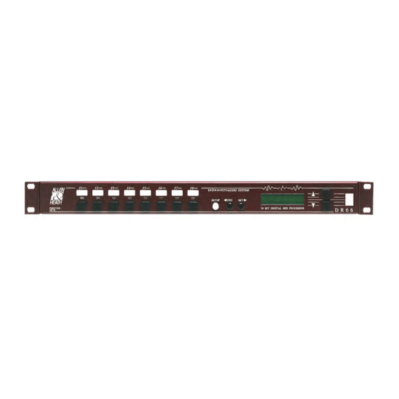
- Page 1 DR66 6 In 6 O UDIO YSTEM 24-Bit Digital Mix Processor SERVICE MANUAL PUBLICATION AP3137...
-
Page 2: How To Use This Manual
CALIBRATION and OPERATION for the DR Section B: contains the SERVICE INFORMATION which includes details of SPARE PARTS & ASSEMBLIES and CIRCUIT BOARD DIAGRAMS for the DR copyright © 1998 ALLEN & HEATH. All rights reserved. Publication..AP3137 Issue 1. DR66 S ERVICE ANUAL... - Page 3 SECTION A 6 INSTALLATION / USER GUIDE CAUTION Refer all installation, calibration and service work to qualified service personnel. DR66 S ERVICE ANUAL...
- Page 4 Warning to the Service Engineer Allen & Heath warns that any unauthorised changes or modifications to the DR66 unit may invalidate the legal compliance of the unit and could void the user’s authority to operate the equipment. DR66 S...
- Page 5 MICROPROCESSOR CPU CIRCUIT DIAGRAM sheet 5 of 6 (processing engine #2)..C2604 MICROPROCESSOR CPU CIRCUIT DIAGRAM sheet 6 of 6 (expander connectors) ..C2604 Refer to SECTION A for information on installation, calibration and operation of the DR66. DR66 S ERVICE...
-
Page 6: Service And Technical Support
The information presented in this section of the manual is intended for competent technical personnel to carry out service and product support for the DR66. We assume that the reader is familiar with the related electronic theory and audio terminology, and is able to carry out basic servicing, fault-finding and repair of digital audio equipment of this type. - Page 7 Keep all batteries away from children. IMPORTANT STATIC ELECTRICITY PRECAUTIONS Many of the components in the DR66 are extremely sensitive to static electricity. The following procedures reduce the possibility of damaging components: 1. Before handling any components or touching anything inside the unit, discharge your body’s static electric charge by touching a grounded (earthed)
- Page 8 DR66 WinDR Disk (3 of 3) 002-362 SERVICE TOOLS The tools required to service the DR66 range of products are standard to an electronics service workshop and are easily obtainable. The following items are necessary for disassembly and service access:...
-
Page 9: Ordering An Assembly
Section B ORDERING AN ASSEMBLY The following assemblies for the DR66 are supplied fully tested. Please quote the description and order code for the part required. Printed circuit (PCB) assemblies: DESCRIPTION ORDER CODE DR1 CPU PCB assembly 002-184 DR66 Converter PCB assembly... -
Page 10: Power Supply
Mains lead IEC-2pin EURO AH0205 Mains lead IEC-3pin UK AH0206 Mains lead IEC-3pin US (C33) AH0323 Transformer 25VA AM3134 Miscellaneous: DR66 Packing assembly 002-294 DR66 Acrylic Fascia AA3145 Rack Mounting brackets (per pair) AA3150-LR Front panel LCD display AE2734 EMI filter 470pF 100V... - Page 11 Section B DR66 BLOCK DIAGRAM DR66 S ERVICE ANUAL...
Need help?
Do you have a question about the DR66 and is the answer not in the manual?
Questions and answers