Maxon CM10 User Manual
Hide thumbs
Also See for CM10:
- User manual (14 pages) ,
- Service manual (4 pages) ,
- User manual (55 pages)
Table of Contents
Advertisement
Available languages
Available languages
Quick Links
User Manual
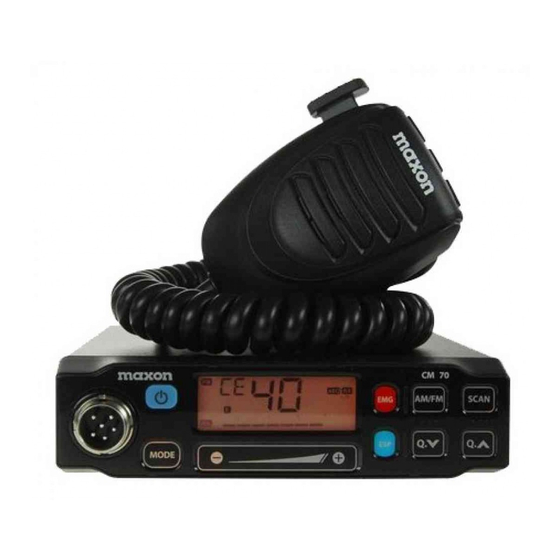
CM70
Declaration of Conformity
We,
MAXON CIC Europe
Ltd, hereby declare under our sole responsibility, that the product:
CB-Radio MAXON CM10/CM70
complies with all the technical regulations applicable to the product in accordance with EU Council
Directives, European Standards and national frequency applications:
73/23/EEC, 89/336/EEC and 99/5/EC
EN 300 135-2 / EN 300 433-2
EN 301 489-1, EN 301 489-13, EN 69050-1
All essential radio test suites have been carried out.
Due to the absence of a harmonised standard covering frequency applications, this CB radio may be used on a frequency
band allowed in the country where the product is used.
An individual licence is required for operating this radio in AM/FM on 40/40 channel in Belgium (BE), Switzerland
(CH), Spain (ES) and Italy (IT).
In Germany (DE) 80/12, 80/40, 40/12 or 40/40 FM/AM channels are allowed; Czech Republic (CZ) 80 FM only;
Estonia (ES), Finland (FI), France (FR), Ireland (IE), Latvia (LV) Netherlands (NL) Poland (PL), Portugal
(PT), and Slovakia (SK) the operation on 40/40 channels in AM/FM is licence free and free of charge.
CEPT 40CH FM only may be used licence and charges free in ALL EU Member States including Norway (NO) &
Iceland (IS), except Austria, where CB radios with multi standard programmable bands are not allowed ,
and Italy and Malta, where individual licence is required.
In order to use this radio in Belgium, Spain and Switzerland, residence must have an individual licence. Users coming
from abroad to these countries may freely use the radio in FM mode, while in order to use it in AM mode, they must hold
a licence released in their own country.
In Great Britain (UK) there is no longer a requirement to possess a Wireless Telegraphy (WT) Act Licence to operate
Citizens' Band Radio equipment, providing that the equipment is operated in accordance with the WT (Exemption)
(Amendment) Regulations 2006.
In Germany, in some border areas, CB radio cannot be used as a base station from channel 41-80. (Refer to local
Circulation Card for
authority (notification office) for details. Travellers arriving in Italy must get an Italian Authorization.
travellers from Germany is necessary in Spain, Finland, Switzerland and Liechtenstein.
Maxon CIC Europe Ltd declares, under their sole responsibility that this apparatus fulfils the requirement of Directive
99/5/EC of the European Parliament and the 9 Council of March of 1999, transposed to the Spanish legislation by means
of Real Decree 1890/2000, on November 20th.
Maxon CIC Europe Ltd declara, bajo su responsabilidad, que este aparato cumple con lo dispuesto en la Directiva 99/5/EC
del Parlamento Europeo y del Consejo de 9 Marzo de 1999, transpuesta a la legislación española mediante el Real Decreto
1890/2000, de 20 de noviembre.
Maxon House, Cleveland Road
Hemel Hempstead, Herts. HP2 7EY
United Kingdom
----------------------------------------------
Hugh Han
Managing Director
June 2008
Page 68 of 68
Advertisement
Table of Contents

Related Manuals for Maxon CM10


Summary of Contents for Maxon CM10
-
Page 1: Declaration Of Conformity
Real Decree 1890/2000, on November 20th. Maxon CIC Europe Ltd declara, bajo su responsabilidad, que este aparato cumple con lo dispuesto en la Directiva 99/5/EC del Parlamento Europeo y del Consejo de 9 Marzo de 1999, transpuesta a la legislación española mediante el Real Decreto 1890/2000, de 20 de noviembre. - Page 2 User Manual CM70 Main Schematic Drawing Page 67 of 68...
- Page 3 User Manual CM70 Compander Circuit Page 66 of 68...
-
Page 4: Block Diagram
User Manual CM70 Block Diagram Page 65 of 68... - Page 5 User Manual CM70 Diagrams (Bottom Layout) Page 64 of 68...
- Page 6 User Manual CM70 Diagrams (Top Layout) Page 63 of 68...
-
Page 7: Updated Information On National Restrictions
User Manual CM70 Updated Information on National Restrictions BELGIUM, SPAIN and SWITZERLAND In order to use this transceiver in Belgium, Spain and Switzerland, users must have an individual licence. Users coming from abroad may freely use the radio in FM mode, while in order to use it in AM mode they must hold a licence issued in their country of residence. - Page 8 User Manual CM70 Table of Restrictions The following information is only to be used as an indication. They are believed to be correct at the time of printing this manual. It is however the user’s responsibility to check that, in the country where radio is used, providing the regulations for the use of CB transceivers have not been modified.
- Page 9 User Manual CM70 Tabela cz stotliwo ci Radiotelefon CM70 jest wyposa ony w nowoczesny uk ad programowania obs uguj cy wiele standardów, który umo liwia programowanie ró nych pasm cz stotliwo ci, parametrów technicznych i trybów pracy zgodnie z przepisami obowi zuj cymi w kraju, w którym urz dzenie jest u ywane. Dost pnych jest 10 programowanych pasm cz stotliwo ci przedstawionych w poni szej tabeli: OZNACZENIE DANE TECHNICZNE (kana , tryb...
-
Page 10: Instalacja Radiotelefonu Cb
User Manual CM70 Instalacja Przed przyst pieniem do monta u jednostki g ównej w samochodzie, nale y starannie wybra dla niej najlepsze miejsce. Dost p do elementów steruj cych powinien by swobodny, a manipulacja nimi nie mo e utrudnia prowadzenia pojazdu. Do zamontowania mo e pos u y obejma b d ca w komplecie. Obejma powinna by mocowana nad lub pod radiotelefonem CB, a samo urz dzenie mo na przechyla zgodnie z potrzebami w zale no ci od rodzaju monta u (pod desk rozdzielcz... - Page 11 User Manual CM70 MIKROFON 16. Przycisk w czaj cy nadawanie PTT W cz przycisk PTT, aby rozpocz nadawanie i wy cz, aby powróci do trybu odbioru. 17. Przycisk zmiany kana u w gór Po ka dym naci ni ciu tego przycisku numer kana u zwi kszy si o 1 w gór . * Mo e by u ywany zamiast przycisku 18.
- Page 12 User Manual CM70 12. Gniazdo EXT zewn trznego g o nika To gniazdo s u y do pod czenia (opcjonalnego) zewn trznego g o nika. 13. Gniazdo miernika poziomu sygna u To gniazdo s u y do pod czenia zewn trznego (opcjonalnego) miernika poziomu sygna u. 14.
- Page 13 9. Przycisk ESP (Elektroniczny procesor mowy) Elektroniczny procesor mowy (ESP) jest now funkcj zastosowan wy cznie w radiotelefonie CB Maxon CM70. CB radio. ESP s u y jako kompresor modulacji nadawanego sygna u i ekspander odbieranego sygna u.
- Page 14 User Manual CM70 Ten przycisk pozwala szybko prze czy si na jeden z dwóch zaprogramowanych kana ów ratunkowych (9 lub 19). Po ka dym naci ni ciu przycisku urz dzenie prze cza si na kana 9, potem na kana 19, a nast pnie przechodzi do kana u roboczego.
- Page 15 User Manual CM70 C. Symbol LOCK (Blokada kana ów) Symbol LOCK pojawia si po w czeniu blokady prze czania kana ów. D. Symbol AM Symbol AM pojawia si , gdy radiotelefon CB nadaje i odbiera sygna z modulacj AM. E. Symbol FM Symbol FM pojawia si , gdy radiotelefon CB nadaje i odbiera sygna z modulacj FM.
-
Page 16: Funkcje I Elementy Sterowania
User Manual CM70 Funkcje i elementy sterowania Panel przedni 1. Przycisk W /WY Przycisk w cza i wy cza radiotelefon CB 2. Wielofunkcyjny wy wietlacz Du y pod wietlany na czerwono wy wietlacz zapewnia czytelno informacji. Na wy wietlaczu pojawiaj si opisy wszystkich uruchomionych funkcji oraz kilka innych informacji (programowanych przez u ytkownika), takich jak: numer kana u lub pe ny 5-znakowy zapis cz stotliwo ci. -
Page 17: Dane Techniczne
User Manual CM70 Dane techniczne Ogólne kana ów………………………………………..………...……………………………...…..40 AM/FM 4W Zakres cz stotliwo ci….………………………………….………….…...…………..…65 do 27,99125 MHz Kontrola cz stotliwo ci……………………………………………….………..…………………tla fazowa PLL Temperatura pracy…………………………………………..……..……..………..………………-10 / +55 C Zasilanie……………………...…………………………..…………...……….....13,2 V pr d sta y 15% Wymiary zewn trzne………….……………………………………182 (d .) X 37 (wys.) X 139 (g .) mm Waga…………………………………………………………………..……..…………………...………………850 g Odbiornik System odbioru………………………………Superheterodyna z podwójn przemian cz stotliwo ci... - Page 18 User Manual CM70 Spis tre ci Dane techniczne ......................42 Funkcje i elementy sterowania ..................42 Mikrofon Dane ......................42 Instalacja ........................42 Instalacja radiotelefonu CB ...................42 Instalacja anteny ......................42 Sprawdzenie dzia ania ....................42 Tabela cz stotliwo ci ....................42 Wybieranie przedzia u cz stotliwo ci ................42 Ograniczenia korzystania z radiotelefonów CB w Europie ..........61 Aktualne informacje o ograniczeniach korzystania z radiotelefonów CB ......62 Schematy .......................
- Page 19 User Manual CM70 Tabella delle bande di frequenza Il ricetrasmettitore CM70 include un circuito programmabile multi-standard avanzato, che consente di programmare su bande di frequenza, parametri e modalità operative diversi, in conformità alle normative vigenti nel paese in cui viene utilizzato il prodotto. Sono disponibili 10 bande di frequenza programmabili, come indicato dalla tabella seguente: CODICE SPECIFICHE (CH, modalità...
-
Page 20: Installazione Dell'antenna
User Manual CM70 Montaggio È opportuno individuare la posizione più comoda per il montaggio dell'unità nel veicolo, in modo che la radio sia facile da raggiungere e da utilizzare durante la guida. Per montare la radio utilizzare la staffa e i materiali forniti. - Page 21 User Manual CM70 MICROFONO 16. Tasto PTT (Push-to-Talk) Tasto trasmettitore. Premere il tasto PTT per trasmettere e rilasciarlo per ritornare in modalità di ricezione. 17. Tasto UP (selettore canale) Ogni volta che il tasto viene premuto, il numero di canale incrementa di uno. * Utilizzabile al posto di 18.
- Page 22 User Manual CM70 13. Jack S-METER Questo jack consente il collegamento di un dispositivo S-METER esterno (facoltativo). 14. Presa ANTENNA Presa per antenna. Consultare la sezione INSTALLAZIONE DELL'ANTENNA. 15. CAVO ALIMENTAZIONE 13.8 CC Ingresso cavo alimentazione 13.8 CC. Page 47 of 68...
- Page 23 9. Tasto ESP (Electronic Speech Processor) La sofisticata funzione ESP (Electronic Speech Processor) è un'esclusiva della radio CB Maxon CM70. La tecnologia ESP (Electronic Speech Processor) funge da compressore della modulazione durante la trasmissione e da espansore della modulazione durante la ricezione.
-
Page 24: Livello Squelch
User Manual CM70 canale operativo normale. Quando viene selezionato uno dei due canali di emergenza, sul display LCD apparirà l'icona EMG (emergenza). La modalità operativa (AM o FM) per i canali di emergenza è pre- programmata come settaggio di fabbrica, in base alla tabella seguente. CODICE PAESE CH-9 CH-19... - Page 25 User Manual CM70 C. Icona LOCK L'icona LOCK è visibile quando viene attivata la funzione di blocco. D. Icona AM L'icona AM è visibile quando la radio riceve e trasmette in modalità AM (onde medie). E. Icona FM L'icona FM è visibile quando la radio riceve e trasmette in modalità FM (modulazione di frequenza). F.
-
Page 26: Comandi E Operatività
User Manual CM70 Comandi e operatività Pannello frontale 1. Accensione/Spegnimento Utilizzare questa manopola per ACCENDERE o SPEGNERE la radio 2. Display LCD L'ampio display retroilluminato in rosso garantisce una perfetta leggibilità. Sul display LCD sono visualizzate tutte le funzioni abilitate oltre a numerose altre funzioni (programmabili dall'utente), quali lettura del canale o lettura della frequenza completa a 5 cifre. - Page 27 User Manual CM70 Specifiche Generale Canali………………………………………..………...……………………………..…..40 Ch AM/FM 4 W Gamma di frequenza……………………………………………………………..da 26.565 a 27.99125 MHz Controllo della frequenza………………………………………………………………………………………PLL Intervallo di temperatura operativa……………………………………………..………….….-10 / +55 C Voltaggio in ingresso CC…………………………...…………………...……………………13,2 V CC 15% Dimensioni……………………………….…………………………180 (larg.) X 37 (alt.) X 139 (prof.) mm Peso……………………………………………………………………………………………………..……0,850 kg Ricevitore Sistema di ricezione………………………………………………….Supereterodina a doppia conversione...
- Page 28 User Manual CM70 Sommario Specifiche ........................42 Comandi e operatività ....................4-8 Microfono ........................48 Installazione ........................49 Installazione dell'unità principale ...................49 Installazione dell'antenna .....................49 Test di operatività ......................49 Tabella delle bande di frequenza ...................50 Selezione delle bande di frequenza .................50 Tabella delle limitazioni ....................61 Informazioni aggiornate sulle restrizioni nazionali ............62 Schemi ........................
- Page 29 User Manual CM70 Frequenzbandtabelle Der CM70-Transceiver verfügt über eine fortgeschrittene Multistandard-Schaltung, die eine Programmierung des Funkgeräts in Bezug auf verschiedene Frequenzbänder, Spezifikationen und Betriebsarten ermöglicht (in Übereinstimmung mit den Vorschriften des Landes, in dem das Produkt verwendet wird). Es sind 10 verschiedene Frequenzbänder verfügbar, die in der folgenden Tabelle aufgeführt sind: SPEZIFIKATIONEN (Kanäle, LÄNDERCODE...
-
Page 30: Installation Des Hauptgeräts
User Manual CM70 Installation Suchen Sie vor dem Einbau des Hauptgeräts im Fahrzeug zuerst den besten Einbauort, damit das Funkgerät gut zugänglich und leicht zu bedienen ist, aber trotzdem kein Sicherheitsrisiko für Fahrer und Beifahrer darstellt. Benutzen Sie die mitgelieferte Halterung und das Montagematerial für den Einbau des Funkgeräts. Die Schrauben der Halterung müssen fest angezogen werden, damit sie sich durch die Vibrationen während der Fahrt nicht lockern können. - Page 31 User Manual CM70 MIKROFON 16. PTT-(Push-to-Talk)-Taste Das ist die Sendetaste. Drücken Sie die PTT-Taste, solange Sie senden (sprechen) wollen. Bei Loslassen der Taste wird wieder in den Empfangsmodus geschaltet. 17. Aufwärts-Taste (für die Kanalwahl) Bei jedem Drücken dieser Taste gehen Sie eine Kanalnummer nach oben. * Kann anstelle von verwendet werden.
- Page 32 User Manual CM70 12. Buchse für externen Lautsprecher (EXT) Diese Buchse dient zum Anschluss eines (optionalen) externen Lautsprechers. 13. Buchse für Signalpegelmessgerät (S-METER) Diese Buchse dient zum Anschluss eines (optionalen) externen Signalpegelmessgeräts. 14. Antennenbuchse Antennenbuchse - siehe Abschnitt INSTALLATION DER ANTENNE. 15.
- Page 33 , um die Lautstärke und den Rauschpegel zu erhöhen oder zu reduzieren. 9. ESP-Taste (elektronischer Sprachprozessor) Der elektronische Sprachprozessor (ESP) ist eine spezielle erweiterte Funktion des Maxon CM70 CB- Funkgeräts. Der ESP fungiert beim Senden als Modulationskompressor und im Empfangsmodus als Modulationsverstärker.
- Page 34 User Manual CM70 Das SCAN-Symbol ist sichtbar, wenn die SCAN-Funktion (automatischer Suchlauf nach belegten Kanälen) aktiviert ist. 3. EMG-Taste (Notrufkanäle) Diese Taste ermöglicht den schnellen Zugriff auf die beiden vorprogrammierten Notrufkanäle (Kanal 9 oder 19). Beim ersten Drücken der Taste schaltet das Funkgerät auf Kanal 9, beim nächsten Drücken auf Kanal 19 und dann wieder auf den normalen Betriebskanal.
- Page 35 User Manual CM70 C. LOCK-Symbol Das LOCK-Symbol ist sichtbar, wenn die LOCK-Funktion aktiviert wurde. D. AM-Symbol Das AM-Symbol ist sichtbar, wenn das Funkgerät im AM-Modus (Amplitudenmodulation) empfängt und sendet. E. FM-Symbol Das FM-Symbol ist sichtbar, wenn das Funkgerät im FM-Modus (Frequenzmodulation) empfängt und sendet. F.
-
Page 36: Steuerung Und Bedienung
User Manual CM70 Steuerung und Bedienung Vorderseite 1. Strom Ein/Aus Mit diesem Knopf wird das Funkgerät ein- und ausgeschaltet. 2. LCD-Display Dieses große, rote Display mit Hintergrundbeleuchtung bietet eine gute Lesbarkeit. Das LCD-Display zeigt alle aktivierten Funktionen sowie mehrere andere Merkmale (vom Benutzer programmierbar), wie z. B. die Kanalnummer oder den vollständigen fünfstelligen Frequenzwert. -
Page 37: Allgemeine Daten
User Manual CM70 Allgemeine Daten Kanäle………………………………………..………...……………………………..40 Kanäle AM/FM 4 W Frequenzbereich………………………………...………………………………..….26,565 bis 27,99125 MHz Frequenzsteuerung……………………………………..………………………………………………….……PLL Betriebstemperaturbereich……………………..……………………………………..…….….-10 C/+55 C Eingangsgleichspannung………...…………………………………………….…13,2 V Gleichstrom 15 % Größe……………………………………….……………………………...……182 (L) x 37 (H) x 139 (T) mm Gewicht…………………………………………………………………………………………………..……0,850 kg Empfänger Empfangssystem…………………………………………...…………...….Doppelüberlagerungsempfänger Zwischenfrequenzen…………………………………………………….1. ZF: 10,695 MHz, 2. ZF: 455 MHZ Empfindlichkeit ………………………………………….…………...………….0,5 V bei 20 db SINAD (FM) Audioverzerrung………………………………………………………..…………..weniger als 8 % @ 1 KHz Spiegelfrequenzunterdrückung…………………………………………………………………………...65 dB... - Page 38 User Manual CM70 Inhalt Technische Daten ......................32 Steuerung und Bedienung ..................33-37 Mikrofon ........................38 Installation ........................39 Installation des Hauptgeräts ..................39 Installation der Antenne ....................39 Funktionsprüfung ......................39 Frequenzbandtabelle ....................40 Frequenzbandauswahl ....................61 Einschränkungstabelle ....................62 Aktuelle Informationen zu nationalen Einschränkungen ...........63 Schaltpläne ......................63-67 Konformitätserklärung ....................68 Page 31 of 68...
- Page 39 User Manual CM70 Table des bandes de fréquences L'émetteur/récepteur CM70 inclut un circuit multistandard programmable avancé qui permet la programmation de différentes bandes de fréquences, spécifications et modes de fonctionnement, en conformité avec les réglementations du pays dans lequel il est utilisé. Dix bandes de fréquences programmables sont disponibles, comme l'indique le tableau suivant : SPÉCIFICATIONS (voie, mode de CODE...
-
Page 40: Installation De L'unité Principale
User Manual CM70 Installation Avant d'installer l'unité principale dans un véhicule, vérifier et sélectionner l'emplacement le plus approprié, pour que la radio soit facile d'accès et d'utilisation confortable, sans toutefois gêner le conducteur ni interférer avec la conduite. Utiliser le support et le matériel fournis pour l'installation. Serrer fermement les vis, pour que le support ne se relâche pas sous l'effet des vibrations du véhicule. - Page 41 User Manual CM70 MICROPHONE 16. Touche PTT Interrupteur d'émission. Chaque pression sur la touche PTT ( Push-To-Talk - Appuyer pour émettre) permet de transmettre. Relâcher la touche pour passer en mode de réception. 17. Sélecteur de voie supérieure Chaque fois que cette touche est actionnée, le numéro de voie monte d'une unité. * Peut être utilisée au lieu de la touche 18.
- Page 42 User Manual CM70 13. Prise S-METER Cette prise permet de connecter un dispositif S-METER externe en option. 14. Connecteur d'antenne Prise permettant le raccordement d'une antenne. Consulter la section relative à l'installation de l'antenne. 15. Cordon d'alimentation 13,8 V CC Cordon électrique de 13,8 volts CC.
- Page 43 - Traitement électronique de la voie) est une fonction avancée exclusive de la radio CB Maxon CM70. Le traitement électronique de la voix agit comme un compresseur de modulation en mode de transmission, et comme un expanseur de modulation en mode de réception. La fonction ESP permet d'obtenir des signaux sonores plus puissants et plus clairs dans les zones bruyantes, particulièrement pour les communications longue distance ou en présence de faibles signaux.
- Page 44 User Manual CM70 3. Touche EMG (voies d'urgence) Cette touche permet d'accéder rapidement à l'une des deux voies d'urgence préprogrammées (voie 9 ou voie 19). Chaque fois que la touche est actionnée, la radio sélectionne la voie 9 puis la voie 19 et, de nouveau, la voie de communication normale.
-
Page 45: Dual Watch
User Manual CM70 C. Icône LOCK L'icône LOCK s'affiche lorsque la fonction de verrouillage est activée. D. Icône AM L'icône AM s'affiche lorsque la radio reçoit et transmet en mode AM (modulation d'amplitude). E. Icône FM L'icône FM s'affiche lorsque la radio reçoit et transmet en mode FM (modulation de fréquence). F. -
Page 46: Commandes Et Fonctionnement
User Manual CM70 Commandes et fonctionnement Panneau avant 1. Marche/Arrêt Ce bouton allume et éteint la radio 2. Écran LCD Ce grand écran rétroéclairé rouge permet une bonne lisibilité. Il affiche toutes les fonctions activées ainsi que d'autres caractéristiques programmées par l'utilisateur, telles que la voie ou la fréquence à cinq chiffres. Le système inclut également un indicateur de puissance des signaux reçus et transmis à... -
Page 47: Spécifications
User Manual CM70 Spécifications Généralités Voies ......................... 40, AM/FM 4W Plage de fréquences................26.565 à 27.99125 MHz Commande de fréquences ....................PLL Température de fonctionnement ................ -10 / +55 C Tension CC en entrée ..................13,2 V CC 15% Dimensions ................182 (L) X 37 (H) X 139 (P) mm Poids ........................... - Page 48 User Manual CM70 Sommaire Spécifications .......................22 Commandes et fonctionnement ................. 23-27 Microphone ........................28 Installation ........................29 Installation de l'unité principale ..................29 Installation de l'antenne ....................29 Essai fonctionnel ......................29 Table des bandes de fréquences ..................30 Sélection des bandes de fréquences ................30 Table de restrictions......................61 Informations à...
- Page 49 User Manual CM70 Tabla de bandas de frecuencia El transceptor CM70 incluye un circuito programable multiestándar avanzado que permite al usuario programar diferentes bandas de frecuencia, especificaciones y modos de funcionamiento (de conformidad con la normativa del país en que se utilice el producto). Hay disponibles 10 bandas de frecuencias programables, conforme a la siguiente tabla: CÓDIGO ESPECIFICACIONES (Canales, modos...
-
Page 50: Instalación De La Unidad Principal
User Manual CM70 Instalación Antes de instalar la unidad principal en un vehículo, compruebe y seleccione el lugar más cómodo, de manera que la radio sea fácilmente accesible y se pueda operar con ella con comodidad y sin interferir en la conducción del vehículo. - Page 51 User Manual CM70 MICRÓFONO 16. Botón PTT (Push-to-Talk) Botón de transmisor. Pulse el botón PTT para transmitir y suéltelo para regresar al modo de recepción. 17. Botón Arriba (selector de canal) Cada vez que se pulsa este botón, aumenta en 1 el número de canal. * Se puede utilizar en lugar de 18.
- Page 52 User Manual CM70 12. Conector (de altavoz externo) EXT Este conector permite la conexión de un altavoz externo (opcional). 13. Conector S-METER Este conector permite la conexión de un S-METER externo (opcional). 14. Conector de antena (ANTENNA) Conector de antena. Consulte la sección INSTALACIÓN DE LA ANTENA. 15.
- Page 53 9. Botón ESP (Electronic Speech Processor: procesador electrónico de voz) ESP (procesador electrónico de voz) es una función avanzada exclusiva de la radio Maxon CM70 CB. ESP funciona como compresor de modulación durante la transmisión y como expansor de modulación durante el modo de recepción.
-
Page 54: Tono De Pitido
User Manual CM70 3. Botón EMG (canales de emergencia) Este botón permite un acceso rápido a uno de los dos canales de emergencia preprogramados (CH9 o CH19). Cada vez que se pulsa este botón, la radio selecciona CH9, luego CH19 y, después, de nuevo el canal de funcionamiento normal. - Page 55 User Manual CM70 C. Icono LOCK El icono LOCK está visible cuando está activada la función LOCK (bloqueo). D. Icono AM El icono AM está visible cuando la radio recibe y transmite en modo AM (modulación de amplitud). E. Icono FM El icono FM está...
-
Page 56: Control Y Utilización
User Manual CM70 Control y utilización Panel delantero 1. Encendido/apagado Este control enciende y apaga la radio 2. Pantalla LCD Esta pantalla grande y con iluminación posterior resulta fácilmente legible. La pantalla LCD muestra todas las funciones activadas, así como otras funciones (programables por el usuario), como la lectura de canales o la lectura de frecuencias completa de 5 dígitos. -
Page 57: Especificaciones
User Manual CM70 Especificaciones Generales Canales………………………………………..…………...……………………………..40 canales AM/FM 4W Rango de frecuencias….……………………………………….………….…...…………..26.565 a 27.99125 Control de frecuencia……………………………………………….……………………………..……………PLL Rango de temperaturas de funcionamiento………………………………………..……….-10 / +55 C Tensión de entrada de CC……………………...………………………………...……..…13,2 V CC 15% Tamaño…………………………………….……………………………………….182(L) X 37(A) X 139(P) mm Peso………………………………………………………………………………………...…………………0,850 kg Receptor Sistema de recepción………………………………………………….Superheterodino de conversión dual Frecuencia intermedia …………………………………………….….1ª... - Page 58 User Manual CM70 Contenido Especificaciones ......................12 Control y utilización ....................13-17 Microfóno ........................18 Instalación ........................19 Instalación de la unidad principal ..................19 Instalación de la antena ....................19 Prueba de funcionamiento ....................19 Tabla de bandas de frecuencia ..................20 Selección de bandas de frecuencia ................20 Tabla de restricciones ....................61 Información actualizada sobre restricciones nacionales ............62 Diagramas ......................
-
Page 59: Frequency Bands Table
User Manual CM70 Frequency Bands Table The CM70 transceiver includes an advanced multi-standard programmable circuit, which allows the user to program different frequency bands, specifications and operating modes (in conformity with the regulations in the country where the product is being used). 10 programmable frequency bands are available, as per the below table: COUNTRY SPECIFICATIONS (CH, operating... -
Page 60: Installation Of Main Unit
User Manual CM70 Installation Before installing the main unit in a vehicle, check and select the most convenient location, so the radio will be easy to reach and comfortable to operate, without disturbing or interfering with operating the vehicle. Use the supplied bracket and hardware to install the radio. The bracket screws must be well tightened in order not to become loose with vehicle vibrations. - Page 61 User Manual CM70 MICROPHONE 16. PTT (Push-to-Talk) Key Transmitter key. Press the PTT key to transmit and release it to return to the receive mode. 17. UP (Channel Selector) Key Each time this key is pressed, the channel number will move upward by one channel. * Can be used instead of 18.
- Page 62 Volume and Squelch level. 9. ESP (Electronic Speech Processor) Key The ESP (Electronic Speech Processor) is an exclusive advanced feature of the Maxon CM70 CB radio. ESP (Electronic Speech Processor), works as a modulation compressor during transmission and as a modulation expander during receive mode.
- Page 63 User Manual CM70 one of the emergency channels is selected, the EMG icon will appear on the LCD display. The operating mode (AM or FM) for the emergency channels are factory pre-programmed as per the following table. COUNTRY CODE CH-9 CH-19 4.
- Page 64 User Manual CM70 C. LOCK Icon The LOCK icon is visible when the LOCK function has been enabled. D. AM Icon The AM icon is visible when the radio receives and transmits in AM mode (amplitude modulation). E. FM Icon The FM icon is visible when radio receives and transmits in FM mode (frequency modulation).
-
Page 65: Control And Operation
User Manual CM70 Control and Operation Front Panel 1. Power On/Off This Button switches the radio ON and OFF 2. LCD Display This large, red backlit system allows clear readability. The LCD display shows all enabled functions as well as several other features (programmable by the user), such as the channel readout or the full 5-digit frequency readout. -
Page 66: Specifications
User Manual CM70 Specifications General Channels………………………………………..………...……………………………..…. 40 Ch AM/FM 4W Frequency Range….………………………………….………….…...…………..….26.565 to 27.99125 MHz Frequency Control……………………………………………….……………………………..…………………PLL Operating Temperature Range……………………………………………..………………….….-10 / +55 C DC Input Voltage……………………...…………………………………...………....…13.2 V DC 15% Size…………………………………….………………………………………..….182(L) X 37(H) X 139(D) mm Weight…………………………………………………………………………………...……………………0.850 kg Receiver Receiving System…………………………………………………….….Dual Conversion Super Heterodyne Intermediate Frequency……………………………….…….……….1 IF: 10.695 MHz, 2 IF: 455 MHZ... - Page 67 User Manual CM70 Contents Specifications ........................3 Control and Operation ....................4-7 Microphone ........................8 Installation ........................9 Installation of Main Unit ....................9 Antenna Installation .......................9 Operational test ......................9 Frequency Bands Table ....................10 Frequency Band Selection .....................10 Table of Restrictions .....................61 Updated Information on National Restrictions ..............62 Diagrams .......................
Need help?
Do you have a question about the CM10 and is the answer not in the manual?
Questions and answers