Table of Contents
Advertisement
Advertisement
Table of Contents

Related Manuals for Midea LRSJ-60/NYN1


Summary of Contents for Midea LRSJ-60/NYN1
-
Page 1: Applicable Models
MDV Swimming Pool Type Heat Pump Water Heater Technical Manual Applicable Models: LRSJ-60/NYN1 LRSJ-80/NYN1 LRSJ-120/NYN1 LRSJ-140/NYN1 Midea reserves the right to discontinue, or change at any time, specifications or designs without notices and without incurring obligations. -
Page 2: Table Of Contents
Contents Part 1 General Information ................3 1. Measurements....................... 4 2. External Appearance .................... 4 3. Nomenclature......................5 4. Features......................... 6 Part 2 Outdoor Units...................7 1. Specifications ....................... 8 2. Capacity&COP table ................... 17 3. Dimensions ......................17 4. Service Space ..................... 18 5. -
Page 3: Part 1 General Information
Part 1 General Information 1. Measurements ..............4 2. External Appearance ............4 3. Nomenclature ..............5 4. Features ................6... -
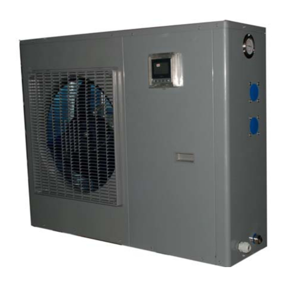
Page 4: Measurements
1. Measurements Dimension Net weight / Gross weight Model Power Supply (mm: W*H*D) (kg) CE-LRSJ-60/NYN1 1015*705*385 64/73 220~240V-1ph-50Hz CE-LRSJ-80/NYN1 220~240V-1ph-50Hz 1015*705*385 66/77 CE-LRSJ-120/NYN1 220~240V-1ph-50Hz 1050*855*315 75/85 CE-LRSJ-140/NYN1 220~240V-1ph-50Hz 1050*855*315 75/85 2. External Appearance LRSJ-60/NYN1 LRSJ-80/NYN1 LRSJ-120/NYN1 LRSJ-140/NYN1... -
Page 5: Nomenclature
3. Nomenclature Household Water Heating Unit 10 11 Design code Refrigerant code Water supply pump lift code Other functions code Power supply specification code Heating mode code whether the system with pump Rated hot water output, unit: 100 W Installation type code cooling recovery code Export model code Export model code... -
Page 6: Features
4. Features 4.1 Titanium heat exchanger a. Excellent prevent eroding material,keep the machine long life. b. High energy efficiency. 4.2 LCD display and build in high pressure meter in refrigerant side User can see the machine running parameter and the state quickly. Engineer can see the machine discharge pressure quickly, get hold of the machine running reliablity . -
Page 7: Part 2 Outdoor Units
Part 2 Outdoor Units 1. Specifications..............8 2. Capacity & COP table .............17 3. Dimensions..............17 4. Service Space..............18 5. Wiring Diagrams .............19 6. System refrigerant Diagrams.........22 7. Exploded View..............22 8. PCB explain ..............22... -
Page 8: Specifications
1. Specifications HPWH SPECIFICATION Model CE-LRSJ-60/NYN1 CE-LRSJ-80/NYN1 CE-LRSJ-120/NYN1 CE-LRSJ-140/NYN1 Power supply Ph-V-hz 220-240V 50Hz 1Ph 220-240V50Hz1Ph 220-240V 50Hz 1Ph 220-240V 50Hz 1Ph Capacity Water Input 1.15 1.52 2.40 2.55 Heating Outdoor ambient (-7℃~38℃) (-7℃~38℃) (-7℃~38℃) (-7℃~38℃) temperature Capacity 10.35 Water Input 1.25... - Page 9 2. Capacity & COP curve...
- Page 10 MODEL : 6 kw...
- Page 12 MODEL :8 kw...
- Page 14 MODEL :12 kw...
-
Page 17: Capacity&Cop Table
Dimensions MODEL 12KW 14KW 1015 1050... -
Page 18: Service Space
4. Service Space... -
Page 19: Wiring Diagrams
5. Wiring Diagrams 6Kw and 8Kw wiring diagrams:... - Page 20 12Kw and 14Kw wiring diagrams:...
-
Page 21: System Refrigerant Diagrams
6. System Rfrigerant Diagrams titanium heat four-way exchanger valve water high pressure pump protection valve evaporator comp. -
Page 22: Exploded View
7. Exploded View MODEL: LRSJ-120/NYN1 & LRSJ-140/NYN1 、... - Page 23 Part Name Quantity Part Name Quantity 12.9 Rear net Wire joint 12.10 Side board Wire clamp Target switch 12.11 Wire joint Main capillary ass'y Handle Titanium heat exchanger Wire controller Hight pressure meter Front side board right side board Front panel Base ass'y Grille Solenoid...
-
Page 24: Pcb Explain
8. PCB explain... - Page 25 ■ A : appliance type dial code CE-LRSJ-60/NYN1 CE-LRSJ-80/NYN1 self-checking self-checking adress :0 adress :1 CE-LRSJ-120/NYN1 CE-LRSJ-140/NYN1 self-checking self-checking adress :2 adress :3...
-
Page 26: Part 3 Installation
Part 3 Installation 1. Precautions ..............277 2. Installation information ..........288 3. Unit Appearance .............29 4. Accessories ..............30 5. Inspecting and Handling the Unit........30 6. Water pipline diagrame ..........30 7. Water pump selection.............31 8. Tools required for installation ........31 9. Electric connection............31... -
Page 27: Precautions
1. Precautions To prevent injury to the user or other people and property damage, the following instructions must be followed. Incorrect operation due to ignoring of instructions may cause harm or damage. The safety precautions listed here are divided into two categories. In either case, important safety instructions are listed to which close attention must be paid. -
Page 28: Installation Information
■ Do not remove the front panel. Some parts inside are dangerous to touch, and a machine malfunction may be caused. ■ Never expose babies, plants or animals directly to the air flow. Adverse influence to babies, animals and plants may be resulted. 2. -
Page 29: Unit Appearance And Composition
■ Carry the unit onto the site In order to avoid scratch or deformation of the unit surface, apply guard boards to the contacting surface. No contact of fingers and other things with the vanes. Don’t incline the unit more than 45° in moving, and keep it vertical when installing. ■... -
Page 30: Accessories
4. Accessories Check whether the following assemblies are complete. Name Quantity Note Purpose Installation& Operation Manual —— Installation and Operation instruction Seal ring —— Discharge condensate water Water outlet jointing pipe —— Discharge condensate water 5. Inspecting and Handling the Unit After delivery, the package should be checked and any damage should be reported immediately to the carrier claims agent. -
Page 31: Water Pump Selection
8.6 Hydraulic circuit test pressure: 3 bars - Hydraulic circuit operating pressure: 1.5 bar pressure drop 2.2 mCE (0.22 bar) 7. Water pump selection Model Water flow Recommendatory flow LRSJ-60/NYN1 0.8~20m3/h 3m3/h LRSJ-80/NYN1 0.8~20m3/h 4m3/h 5m3/h LRSJ-120/NYN1 1.5~20m3/h 5.8m3/h LRSJ-140/NYN1 1.5~20m3/h... -
Page 32: Electric Wiring
Diameter of the main line (a): Get from the power supply specification table according to the sum of horsepower of the unit. Diameter of the wiring from the junction box to the power supply equipment: When the water heaters are less than 5 sets, the diameter the wiring from the junction box to the power supply equipment should be the same as the main line (a);... -
Page 33: Part 4 Trial Operation
Part 4 Trial Operation 1. Confirmation Before the Trial Operation ......34 2. Operating Instruction .............34 3. Fault code list........4. Self-checking........ -
Page 34: Confirmation Before The Trial Operation
1. Confirmation Before the Trial Operation 1.1 All the installation is complete. 1.2 Water heater is installed correctly. 1.3 The pipelines and wiring are correct. 1.4 The accessories are installed correctly. 1.5 The drainage is smooth. 1.6 The thermal insulation is sound. 1.7 The earthing wire is connected correctly. - Page 35 Names of keys on the wire controller and the keypad operation description Application of wire controller Preparation before running the unit. When you run the unit for the first time, all the indicators on the wire controller will light for 3s, and then, display the fiducial web page.
- Page 36 Temperature set Temp. displayed is the setting water temp. Default is 28℃ and the Cool mode setting range is 10~30℃the heat mode setting range is 20~35℃ Power on/Power off Press Power On/Power Off button after all the above have finished and the system will run as the setting.
- Page 37 3. Fault code list 4. Self-checking function Nomal display : T6 ; Mode code :(0 6KW; 1 8KW; 2 12KW; 3 14KW) ; Operate mode:(1 cooling;16 water heating;4 pump ) ; Fan speed(0 stop;1 low ;2 hight) ; T4; Tp; T3;...
Need help?
Do you have a question about the LRSJ-60/NYN1 and is the answer not in the manual?
Questions and answers