
Related Manuals for Toro Z Master Commercial 2000 74141TE


Summary of Contents for Toro Z Master Commercial 2000 74141TE
-
Page 1: Side Discharge
Form No. 3375-556 Rev A Z Master ® Commercial 2000 Series Riding Mower with 48in TURBO FORCE ® Side Discharge Mower Model No. 74141TE—Serial No. 313000001 and Up *3375-556* A Register at www.Toro.com. Original Instructions (EN) -
Page 2: Introduction
WARNING Removing standard original equipment parts and accessories may alter the warranty, traction, and safety of the machine. Failure to use original Toro parts could cause serious injury or death. Making unauthorized changes to the engine, fuel or venting system, may violate regulations. -
Page 3: Table Of Contents
Checking the Tire Pressure ........38 Safety ................4 Adjusting the Caster Pivot Bearing ......39 Safe Operating Practices........... 4 Adjusting the Electric Clutch........39 Toro Riding Mower Safety ........5 Cooling System Maintenance ........40 Sound Pressure ............6 Cleaning the Engine Screen........40 Sound Power ............6 Cleaning the Engine Cooling Fins and Vibration Level ............ -
Page 4: Safety
Safety • Warning–Fuel is highly flammable. – Store fuel in containers specifically designed for this purpose. This machine meets or exceeds European Standards in effect at the time of production. However, improper use – Refuel outdoors only and do not smoke while or maintenance by the operator or owner can result in refuelling. -
Page 5: Toro Riding Mower Safety
• Never operate the machine with damaged guards or without safety protective devices in place. The following list contains safety information specific to Toro • Do not change the engine governor settings or overspeed products or other safety information that you must know that the engine. -
Page 6: Sound Pressure
• Follow the manufacturer's recommendations for wheel weights or counterweights to improve stability. • Use extreme care with grass catchers or other attachments. These can change the stability of the machine and cause loss of control. Sound Pressure This unit has a sound pressure level at the operator’s ear of 91 dBA, which includes an Uncertainty Value (K) of 1 dBA. -
Page 7: Slope Indicator
Slope Indicator G011841 Figure 3 This page may be copied for personal use. 1. The maximum slope you can safely operate the machine on is 15 degrees. Use the slope chart to determine the degree of slope of hills before operating. Do not operate this machine on a slope greater than 15 degrees. Fold along the appropriate line to match the recommended slope. -
Page 8: Safety And Instructional Decals
Safety and Instructional Decals Safety decals and instructions are easily visible to the operator and are located near any area of potential danger. Replace any decal that is damaged or lost. 58-6520 1. Grease Battery Symbols Some or all of these symbols are on your battery 1. - Page 9 106-5517 1. Warning—do not touch the hot surface. 112-3858 1. Read the Operator's 3. Remove the ignition key Manual. before adjusting the height of cut. 2. Read the instructions 4. Height of cut settings. before servicing or performing maintenance. 112-9028 1.
- Page 10 117-3848 1. Thrown object hazard—keep bystanders a safe distance from the machine. 2. Thrown object hazard, mower—do not operate the without deflector, discharge cover or grass collection system in place. 3. Cutting/dismemberment of hand or foot—stay away from moving parts; keep all guards and shields in place. 117-0346 1.
- Page 11 117-8639 1. Belt routing 2. Grease pulley, maintenance interval—50 hours 121–4777 1. Height of cut adjustment 2. Read the Operator’s Manual on information on how to lock and unlock the deck position. 119-2501 1. Choke 3. Slow 2. Fast 4. PTO (Power Take-off) 114–4468 1.
-
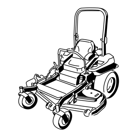
Page 12: Product Overview
A selection of Toro approved attachments and accessories is available for use with the machine to enhance and expand its capabilities. Contact your Authorized Service Dealer or Distributor or go to www.Toro.com for a list of all approved attachments and accessories. G017418 Figure 5 4. -
Page 13: Specifications
Specifications Operation Note: Specifications and design are subject to change Note: Determine the left and right sides of the machine without notice. from the normal operating position. Width: Adding Fuel 48 inch Deck Without Deck 45.3 inches (115.1 cm) • For best results, use only clean, fresh, unleaded gasoline Deflector Up 51.5 inches (130.8 cm) -
Page 14: Checking The Engine Oil Level
Filling the Fuel Tank DANGER Note: Do not fill the fuel tank completely full. Fill the fuel In certain conditions during fueling, static tank to the bottom of the filler neck. The empty space in the electricity can be released causing a spark which tank allows the gasoline to expand. -
Page 15: Breaking In A New Machine
Breaking In a New Machine New engines take time to develop full power. Mower decks and drive systems have higher friction when new, placing additional load on the engine. Allow 40 to 50 hours of break-in time for new machines to develop full power and best performance. -
Page 16: Operating The Parking Brake
The use of protective equipment for eyes, ears, feet and head DANGER is recommended. Operating on wet grass or steep slopes can cause sliding and loss of control. Wheels dropping over edges can cause rollovers, which may result in serious injury, death or drowning. -
Page 17: Operating The Mower Blade Control Switch (Pto)
Operating the Mower Blade Operating the Choke Control Switch (PTO) Use the choke to start a cold engine. 1. If the engine is cold, use the choke to start the engine. The blade control switch (PTO) starts and stops the mower blades and any powered attachments. -
Page 18: Using The Fuel Shut-Off Valve
Starting and Stopping the Engine Starting the Engine 1. Raise the ROPS up and lock into place, sit on the seat and fasten the seat belt. 2. Move the motion controls to neutral locked position. G008947 3. Set the parking brake; refer to Setting the Parking Figure 16 Brake. -
Page 19: The Safety Interlock System
G008947 Figure 19 1. Off 3. Start 2. Run Stopping the Engine CAUTION Children or bystanders may be injured if they move or attempt to operate the machine while it is unattended. Always remove the ignition key and set the parking brake when leaving the machine unattended, even if just for a few minutes. -
Page 20: Driving Forward Or Backward
Understanding the Safety Interlock CAUTION System Machine can spin very rapidly. Operator may lose control of machine and cause personal injury or The safety interlock system is designed to prevent the engine from starting unless: damage to machine. • The parking brake is engaged. •... -
Page 21: Stopping The Machine
take off (blade control switch (PTO), and turn the ignition key to off. Set the parking brake when you leave the machine; refer to Setting the Parking Brake in Operation. Remember to remove the key from the ignition switch. CAUTION Children or bystanders may be injured if they move or attempt to operate the machine while it is unattended. -
Page 22: Adjusting The Anti-Scalp Rollers
Adjusting the Height-of-Cut Pin Mower deck size Height-of-cut Increments range 48 inch 1-1/2 to 5 inches 1/4 inch (6 mm) (38 to 127 mm) The height-of-cut is adjusted by relocating the clevis pin into different hole locations. 1. Move the transport lock to the lock position. 2. -
Page 23: Positioning The Seat
Using the Drive Wheel Release Valves WARNING Hands may become entangled in the rotating drive components below the engine deck, which could result in serious injury. Stop the engine, remove the key, and allow all moving parts to stop before accessing the drive g017628 wheel release valves. -
Page 24: Using The Side Discharge
5. To run the machine, move the bypass levers to the WARNING forward position (Figure 29). Loading a unit onto a trailer or truck increases the possibility of backward tip-over and could cause Using the Side Discharge serious injury or death. The mower has a hinged grass deflector that disperses •... -
Page 25: Transporting Machines
Transporting Machines Use a heavy-duty trailer or truck to transport the machine. Ensure that the trailer or truck has all necessary brakes, lighting, and marking as required by law. Please carefully read all the safety instructions. Knowing this information could help you, your family, pets or bystanders avoid injury. -
Page 26: Operating Tips
File down any nicks and sharpen the it is late fall when grass grows more slowly. blades as necessary. If a blade is damaged or worn, replace it immediately with a genuine TORO replacement blade. Mowing Direction Alternate mowing direction to keep the grass standing straight. -
Page 27: Maintenance
Maintenance Recommended Maintenance Schedule(s) Maintenance Service Maintenance Procedure Interval • Change the engine oil. After the first 8 hours • Change the hydraulic system filter and oil. After the first 50 hours • Check the safety system. • Check the engine oil level. •... -
Page 28: Lubrication
Lubrication Yearly—Grease the front caster pivots (more often in dirty or dusty conditions). 1. Disengage the blade control switch (PTO), move the Greasing and Lubrication motion control levers to the neutral locked position, and set the parking brake. Grease more frequently when operating conditions are extremely dusty or sandy. -
Page 29: Lubricate The Caster Wheel Hubs
Lubricate the Caster Wheel 14. Torque the nut to 8-9 N-m (75-80 in-lb), loosen, then re-torque to 2-3 N-m (20-25 in-lb). Make sure that the Hubs axle does not extend beyond either nut. Install the seal guards over the wheel hub and insert Service Interval: Yearly the wheel into the caster fork. -
Page 30: Engine Maintenance
Engine Maintenance WARNING Contact with hot surfaces may cause personal injury. Keep hands, feet, face, clothing and other body parts away the muffler and other hot surfaces. Servicing the Air Cleaner Service Interval: Every 250 hours—Replace the primary air filter. Figure 36 Every 250 hours—Check the secondary air filter. -
Page 31: Servicing The Engine Oil
Servicing the Engine Oil Oil Type: Detergent oil (API service SF, SG, SH, SJ, or SL) Crankcase Capacity: with a filter change, 71 ounces (2.1 L); without a filter change, 61 ounces (1.8 L) Viscosity: See the table below. G008804 Figure 37 Note: Use of multi-grade oils (5W-20, 10W-30, or 10W-40) will increase oil consumption. -
Page 32: Changing The Engine Oil
Changing the Engine Oil Service Interval: After the first 8 hours Every 100 hours (more often in dirty or dusty conditions). Note: Dispose of the used oil at a recycling center. 1. Park the machine so that the rear is slightly lower than the front to ensure the oil drains completely. -
Page 33: Servicing The Spark Plug
Removing the Spark Plug 1. Stop the engine, remove the key, and wait for all moving parts to stop before leaving the operating position. 2. Disengage the PTO, move the motion control levers to the neutral locked position and set the parking brake. G017452 3. -
Page 34: Check Spark Arrester (If Equipped)
Installing the Spark Plug Fuel System Tighten the spark plug(s) to 16 ft.-lb (22 N-m). Maintenance Replacing the Fuel Filter Service Interval: Every 500 hours/Yearly (whichever comes first) (more often in dirty or dusty conditions). The fuel filter is located near the engine on the front or rear side of the engine. -
Page 35: Servicing The Fuel Tank
Servicing the Fuel Tank Electrical System Maintenance Do not attempt to drain the fuel tank. Ensure that an Authorized Service Dealer drains the fuel tank and services any components of the fuel system. Servicing the Battery Service Interval: Monthly DANGER Battery electrolyte contains sulfuric acid which is a deadly poison and causes severe burns. -
Page 36: Servicing The Fuses
5. Remove the wing nut securing the battery clamp prevent battery damage when the temperature is below (Figure 46). 32°F (0°C). 6. Remove the clamp (Figure 46). 1. Charge battery for 10 to 15 minutes at 25 to 30 amps or 30 minutes at 10 amps. -
Page 37: Drive System Maintenance
Drive System Maintenance Checking the Seat Belt Service Interval: Before each use or daily Visually inspect seat belt for wear, cuts, and proper operation of retractor and buckle. Replace before operating if damaged. Checking the Rollover Protection System (ROPS) G017436 Knobs Figure 48 Service Interval: Before each use or daily... -
Page 38: Adjusting The Tracking
8. Tighten the stop plate (Figure 50). Figure 50 Left control lever shown 1. Control lever 3. Stop plate 2. Bolt Figure 49 1. ROPS knob (locked 3. Roll bar in the upright Checking the Tire Pressure position) position 2. Pull ROPS knob out and 4. -
Page 39: Adjusting The Caster Pivot Bearing
Adjusting the Caster Pivot 2. If adjustment is needed, then set at .015 inches (0.381 mm) for each of the three adjustment slot positions. Bearing Tighten the lock nuts until there is slight binding on the feeler gauge but it can be moved easily within the Service Interval: Every 500 hours/Yearly (whichever comes air gap (Figure 53). -
Page 40: Cooling System Maintenance
Belt Maintenance Cooling System Maintenance Inspecting the Belts Cleaning the Engine Screen Service Interval: Every 50 hours Service Interval: Before each use or daily Check the belts for squealing when the belt is rotating, blades slipping when cutting grass, frayed belt edges, burn marks and Before each use remove any build-up of grass, dirt or cracks are signs of a worn mower belt. -
Page 41: Replacing The Hydraulic Pump Drive Belt
g017496 Figure 57 1. Position the belt cover 3. Install the bolt 2. Slide belt cover under the side catches Replacing the Hydraulic Pump Drive Belt Figure 56 1. Clutch pulley 5. Square hole in the idler 1. Disengage the PTO and set the parking brake. arm for the ratchet 2. -
Page 42: Controls System Maintenance
Controls System Maintenance Adjusting the Control Handle Position There are two height positions for the control levers; high and low. Remove the bolts to adjust the height for the operator. 1. Disengage the PTO, move the motion control levers to the neutral locked position, and set the parking brake. -
Page 43: Adjusting The Motion Control Linkage
6. Run the unit at least 5 minutes with the drive levers at full forward speed to bring hydraulic oil up to operating temperature. Note: The motion control lever needs to be in neutral while making any necessary adjustments. 7. Bring the motion control levers into the neutral position. -
Page 44: Adjusting The Motion Control Neutral Lock Pivot
1. Allow the hydraulic oil to cool down. Check the oil 2. Most resistance (firmest feel) level when the oil is cold. 3. Damper 2. Check expansion reservoir and if necessary add Toro ® 4. Medium resistance (medium feel) HYPR-OIL ™... -
Page 45: Changing The Hydraulic System Filter And Oil
Changing the Hydraulic System Filter and Oil The filter and oil are changed at the same time. Do Not reuse oil. Once the new filter is installed and oil is added any air in the system must be purged. The bleeding process is repeated until the oil remains at the FULL COLD line in the reservoir after purging. -
Page 46: Mower Deck Maintenance
Bleeding the Hydraulic System Mower Deck 1. Raise the rear of machine up and support with jack Maintenance stands (or equivalent support) just high enough to allow drive wheels to turn freely. Leveling the Mower Deck Setting Up the Machine Note: Ensure the mower deck is leveled before matching the height-of-cut (HOC). - Page 47 6. Insert the height adjustment pin into the 3 inch (7.6 cm) cutting height location. 7. Release the transport lock and allow the deck to lower to the cutting height. 8. Raise the discharge chute. 9. On both sides of the deck, measure from the level surface to the front tip of the blade (Postion A).
-
Page 48: Servicing The Cutting Blades
File down any nicks and sharpen the blades as necessary. If a blade is damaged or worn, replace it immediately with a genuine Toro replacement blade. For convenient sharpening and replacement, you may want to keep extra blades on hand. -
Page 49: Inspecting The Blades
Inspecting the Blades Checking for Bent Blades 1. Disengage the blade control switch (PTO), move the Service Interval: Before each use or daily motion control levers to the neutral locked position 1. Inspect the cutting edges (Figure 74). If the edges and set the parking brake. - Page 50 Toro replacement blades. Replacement blades made 2. Check the balance of the blade by putting it on a blade by other manufacturers may result in non-conformance with balancer (Figure 78). If the blade stays in a horizontal safety standards.
-
Page 51: Removing The Mower Deck
Removing the Mower Deck Before servicing or removing the mower deck, the spring loaded deck arms must be locked out. 1. Stop engine, wait for all moving parts to stop, and remove key. Engage parking brake. 2. Remove the height adjustment pin and lower the deck to the ground. -
Page 52: Replacing The Grass Deflector
Replacing the Grass Deflector Cleaning WARNING Cleaning Under the Mower An uncovered discharge opening could allow the lawn mower to throw objects in the operator's or Service Interval: Before each use or daily bystander's direction and result in serious injury. 1. -
Page 53: Storage
Storage C. Stop the engine, allow it to cool, and drain the fuel tank; refer to Servicing the Fuel Tank in the Maintenance Section. Cleaning and Storage D. Restart the engine and run it until it stops. 1. Disengage the power take off (blade control switch E. -
Page 54: Troubleshooting
Troubleshooting Problem Possible Cause Corrective Action Starter does not crank 1. Blade control switch (PTO) is engaged. 1. Move blade control switch (PTO) to disengaged. 2. Parking brake is not on. 2. Set the parking brake. 3. Drive levers are not in neutral lock 3. - Page 55 Problem Possible Cause Corrective Action Machine does not drive. 1. By pass valves is not closed tight. 1. Tighten the by pass valves. 2. Pump belt is worn, loose or broken. 2. Change the belt. 3. Pump belt is off a pulley. 3.
-
Page 56: Schematics
Schematics g018479 Wire Diagram (Rev. A) - Page 57 Notes:...
- Page 58 Notes:...
- Page 59 The Way Toro Uses Information Toro may use your personal information to process warranty claims, to contact you in the event of a product recall and for any other purpose which we tell you about. Toro may share your information with Toro's affiliates, dealers or other business partners in connection with any of these activities. We will not sell your personal information to any other company.
- Page 60 Instructions for Obtaining Warranty Service The Toro Company and its affiliate, Toro Warranty Company, pursuant to If you think that your Toro Product contains a defect in materials or an agreement between them, jointly promise to the original purchaser workmanship, follow this procedure: to repair the Toro Products listed below if defective in materials or 1.
Need help?
Do you have a question about the Z Master Commercial 2000 74141TE and is the answer not in the manual?
Questions and answers