Table of Contents
Advertisement
TopPage
CHAPTER 1. SPECIFICATION
[1]
SPECIFICATION ...........................................1-1
[2]
EXTERNAL DIMENSION ..............................1-2
[3]
CAPACITY TABLE.........................................1-2
[4]
ELECTRICAL PARTS....................................1-4
[5]
WIRING DIAGRAMS .....................................1-4
CHAPTER 2. EXPLANATION OF CIRCUIT AND OP-
ERATION
[1]
BLOCK DIAGARM.........................................2-1
[2]
FUNCTIONS..................................................2-2
[1]
TIONS............................................................3-1
[2]
TROUBLESHOOTING GUIDE ......................3-2
Parts marked with "
" are important for maintaining the safety of the set. Be sure to replace these parts with specified ones for maintaining the
safety and performance of the set.
SERVICE MANUAL
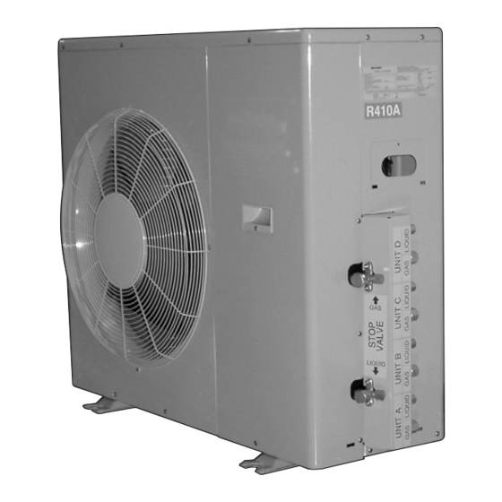
MULITI SPLIT TYPE
ROOM AIR CONDITIONERS
OUTDOOR UNIT
MODEL
AE-XM30GR
In the interests of user-safety (Required by safety regulations in some countries)
the set should be restored to its original condition and only parts identical to those
specified should be used.
CONTENTS
[1]
REFRIGERATION SYCLE ..................... . ....... 4-1
[2]
WORKS.................................................. . ....... 4-3
[1]
OUTDOOR UNIT ................................... . ....... 5-1
S9619AEXM30GR
This document has been published to be used for
after sales service only.
The contents are subject to change without notice.
AEXM30GR
Advertisement
Table of Contents

Related Manuals for Sharp AE-XM30GR


Summary of Contents for Sharp AE-XM30GR
-
Page 1: Table Of Contents
MULITI SPLIT TYPE ROOM AIR CONDITIONERS OUTDOOR UNIT MODEL AE-XM30GR In the interests of user-safety (Required by safety regulations in some countries) the set should be restored to its original condition and only parts identical to those specified should be used. -
Page 2: Specification
AE-XM30GR CHAPTER 1. AE-XM30GR SPECIFICATION Service Manual [1] SPECIFICATION MODEL INDOOR UNIT OUTDOOR UNIT ITEMS AY-XPM7FR/9FR/12FR AE-XM30GR Cooling capacity 4-INDOOR OPERTION 9K&7K&7K&7K 8.4(4.3–9.0)* Heating capacity 4-INDOOR OPERTION 9K&7K&7K&7K 9.0(4.4–10.6)* Moisture removal (at cooling)✩ Liters/h 1.0&0.8X3* Electrical data Phase Single Rated frequency... -
Page 3: External Dimension
AE-XM30GR [2] EXTERNAL DIMENSION 51.3 ¿4.5 [3] CAPACITY TABLE Recommended Combination Indoor Units Outdoor Units AY-XPM7/9/12FR,GS-XPM9/12/18FGR,GS-XPM7/9/12FR AE-XM30FR 1 – 2... - Page 4 AE-XM30GR COOLING CAPACITY TABLE Combination of Indoor Power Consumption Operating Cooling Capacity (kW) Running Current (A) Units Status RATING (Min.-Max.) RATING (Min.-Max.) RATING (Min.-Max.) 2.65 2.65 1.55 1.55 8.4 (4.3-9.0) 13.7 (4.9-16.0) 2990 (1070-3490) 2.73 2.04 2.04 1.59 8.4 (4.3-9.0) 13.7 (4.9-16.0)
-
Page 5: Electrical Parts
AE-XM30GR Combination of Indoor Power Consumption Heating Capacity (kW) Running Current (A) Operat- Units ing Status RATING (Min.-Max.) RATING (Min.-Max.) RATING (Min.-Max.) 4.86 3.24 8.1 (3.6-9.0j 11.2 (3.8-15.1) 2450 (830-3300) 5.40 2.70 8.1 (3.6-9.0j 11.2 (3.8-15.1) 2450 (830-3300) 5.54 2.16 7.7 (3.6-9.0j... - Page 6 AE-XM30GR CONTROL P.W.B and DISPLAY P.W.B 1 – 5...
- Page 7 AE-XM30GR from CONTROL PWB from ELECTROLTIC CN14 CAPACITOR C10 "-" from ELECTROLTIC CAPACITOR C10 "+" from COMPRESSOR CORD W "ORANGE" from COMPRESSOR CORD V "WHITE" from COMPRESSOR CORD U "RED" from CONTROL PWB BCN2 from CONTROL PWB BCN1 IPM P.W.B.
- Page 8 AE-XM30GR 1 – 7...
-
Page 9: Block Diagarm
AE-XM30GR CHAPTER 2. AE-XM30GR EXPLANATION OF CIRCUIT AND OPERATION Service Manual [1] BLOCK DIAGARM 20 A Fuse Fuse Power supply Smoothing Active filter Filter AC power circuit circuit circuit circuit CPU oscillator circuit DC power supply circuit DC over voltage... -
Page 10: Functions
AE-XM30GR [2] FUNCTIONS 1. FREQUENCY CONTROL 2. OVER CURRENT PROTECTION 1) AC current peak control DC over current detection, AC over current detection To protect against over current due to sudden change in load, the compressor is Cooling mode Heating mode stopped if 55A DC is exceeded in the DC section. - Page 11 AE-XM30GR 9. PUMP DOWN SWITCH When the PUMP DOWN SWITCH (SW1) is pressed for 5 seconds or More than More than More than more, the total A/C system will start its TEST RUN automatically and 20 min. 20 min. 20 min.
-
Page 12: Chapter 3. Function And Operation Of Pro- Tective Procedures Protective Functions And Opera- Tions
CHAPTER 3. FUNCTION AND OPERATION OF PROTECTIVE PROCEDURES [1] PROTECTIVE FUNCTIONS AND OPERATIONS Operation Function Description Detection time Restart condition Compressor is stopped if a current approxi- During compres- Automatically restarts after DC over current mately 25A or more flows in the power tran- 4 times sor operation safety time (180 seconds) -
Page 13: Troubleshooting Guide
Operation Function Description Detection time Restart condition Lowers the operating frequency if the tem- IPM overheat pre- perature of IPM rises high temperature. vention control. During compres- Automatically restarts after Stops the compressor if the tem-perature No limit IPM high tempera- sor operation safety time.(180 sec.) srays high for 2 minuteS at minumum fre-... - Page 14 3 – 3...
- Page 15 3 – 4...
- Page 16 Figure 1 Temperature properties of indoor thermistors Room temperature Thermistor Signal Color thermistor TH1 (CN6 3 - 4 ) Room temperature Yellow Heat exchange Heat exchange Orange Heat exchange thermistor thermistor TH2 (CN6 1 - 2 ) Pipe temperature Black TH2 (Orange), TH3 (Black) Pipe temperature 25ºC resistance 4.431 k...
- Page 17 Thermistor Connector Color Connector pin Outdoor temp. thermistor CN8A Green No. 5 to 6 Suction thermistor CN8A Black No. 7 to 8 Thermistor unit A (suction) CN8C Blue No. 1 to 2 Thermistor unit B (suction) CN8C White No. 3 to 4 Thermistor unit C (suction) CN8C Brown...
- Page 18 3 – 7...
- Page 19 2. When one room is not cooled (other rooms are cooled) 3 – 8...
- Page 20 3. When all rooms are not heated Does the air get cooler in the cooling operation mode? Refer to 1 All rooms are Press the ON switch on the not cooled. remote control to run the air conditioner. Set the temperature to 32 in the heating mode and start operation.
-
Page 21: Chapter 4. Refrigeration Cycle
Expansion valve B Heat exchanger UNIT A Expansion valve A Heat exchanger STOP valve (Gas) INDOOR UNIT OUTDOOR UNIT (AE-XM30GR) 2. [18] class indoor unit is connected UNITA STOP valve (Liquid) Expansion valve D UNIT C Expansion valve C Heat exchanger... - Page 22 UNIT D UNIT C UNIT B UNIT A INDOOR UNIT OUTDOOR UNIT (AE-XM30GR) Cooling heating 3. Cycle temperature and pressure in stop valve (AE-XM30GR) Running unit no operation mode Cool (MAX) Cool (Test run) Heat (MAX) Heat (Test run) AY-XPM9FR &...
-
Page 23: Refrigerant Pipe Installation Works
AE-XM30GR 4. PERFORMANCE CURVES At Heating for AY-XPM9FR (for AE-XM30GR) NOTE: Total cooling capacity and total input with 4 units running. (Running frequency: 70HZ) 3200 (Running frequency: 70HZ) 3000 3200 2800 3000 2600 2800 2400 2600 2400 Outside air temp. (ºC) 7 .0... -
Page 24: Pump Down
AE-XM30GR 8) Fully open the stop valve (gas side) with hexagon socket screw 4. MISWIRING CHECK key. Turn all the way up to contact. Miswiring check must be performed after installation, reinstallation and 9) Disconnect the gauge manifold hose from the service port. -
Page 25: Chapter 5. Disassembling Procedure
AE-XM30GR CHAPTER 5. AE-XM30GR DISASSEMBLING PROCEDURE Service Manual [1] OUTDOOR UNIT 1. PROCEDURE 4. Remove the 6 screws fixing the rear guard. 1. Remove the 5 screws fixing the front panel R and slide the front panel R down. 5. Remove the 11 screws fixing the side cover R. - Page 26 AE-XM30GR 7. Cut the insulators. 12.Remove the terminal cover and disconnect 3 terminals. 8. Remove the 2 screws fixing the control box cover. CAUTION: Discharge electrolytic capacitor before touching this capac- itor or other components or wirings. Screws NOTE: Caution to the connectors' position when reinstalling.
- Page 27 AE-XM30GR 15..Remove the 3 screws fixing the bulkhead. 17.Remove the 1 nut fixing the propeller fan. L oos e 18.remove the 2 screws fixing the motor angle. 19.Cut the fixing bands. 16.Remove the 3 screws fixing the active coil. 5 – 3...
- Page 28 AE-XM30GR 20.Remove the 4 screws fixing the fan motor. B lack 2. Position of the thermistors NOTE: Caution to the position when reinstalling. Green Y ellow B rown Orange White B lue 5 – 4...
- Page 29 AE-XM30GR 3. How to disassemble the control box assembly 1. Remove the 4 screws fixing the PWB. 2. Unlock the spacer's lock. The position of setting Ferrite core (FC1 – FC12) FC10 FC12 FC11 5 – 5...
- Page 30 AE-XM30GR 4. Mounting position of thermistors and expansion valves Mounting position of thermistors and expansion valves are shown below. Thermistor • Check the cord color of thermistor before mounting. • Thermistor Suction, UNIT A, UNIT B, UNIT C and UNIT D are mounted on GAS side pipes.
-
Page 31: Parts Guide
AE-XM30GR PartsGuide PARTS GUIDE MULITI SPLIT TYPE ROOM AIR CONDITIONERS OUTDOOR UNIT AE-XM30GR MODEL CONTENTS OUTDOOR UNIT PARTS 1 PACKING PARTS OUTDOOR UNIT PARTS 2 INDEX OTHER OUTDOOR UNIT HOW TO ORDER REPLACEMENT PARTS To have your order filled promptly and correctly, please furnish the following information. - Page 32 AE-XM30GR [1] OUTDOOR UNIT PARTS 1 2-37 2-23 2-40 1-44 4-10 4-10 1-45 2-24 2-26 1-50 2-25 1-48 2-20 4-11 1-60 2-17 2-28 1-61 1-12 1-66 4-12 2-20 2-19 1-58 1-36 4-14 2-55 1-66 1-63 4-13 1-76 2-38 1-52 2-41...
- Page 33 AE-XM30GR PRICE PART PARTS CODE DESCRIPTION RANK MARK RANK [1] OUTDOOR UNIT PARTS 1 Fan motor CMOTLB051JBEZ Terminal board angle LANG-A540JBWZ Cord holder LHLD-A539JBFA Cord clamp holder LHLD-A544JBFA 1-5-1 Terminal board QTANZA020JBZZ 1-5-2 Terminal board QTANZA021JBZZ 1-11 Control box ass'y...
- Page 34 AE-XM30GR [2] OUTDOOR UNIT PARTS 2 3-14 3-21 2-33 3-35 3-25 1-69 3-35 3-24 3-10 1-54 3-17 1-78 2-35 1-79 3-12 3-1-1 3-23 3-17 1-73 3-1-1 3-17 3-1-1 3-18 3-22 2-67 2-69 3-13 3-1-2 2-68 3-33 3-11 3-31 3-34 3-30...
- Page 35 AE-XM30GR PRICE PART PARTS CODE DESCRIPTION RANK MARK RANK [2] OUTDOOR UNIT PARTS 2 1-54 Compressor cord QW-IZA100JBZZ 1-69 Thermistor RH-HXA032JBZZ 1-73 Thermistor RTHM-A022JBEO 1-78 Thermistor RH-HXA054JBZZ 1-79 Thermistor spring MSPR-A027JBEO 2-16 Flare coupling base PDAI-A114JBTB 2-29 Flare cou. Sub-s...
- Page 36 AE-XM30GR PRICE PART PARTS CODE DESCRIPTION RANK MARK RANK [3] OTHER OUTDOOR UNIT 1-30 Relay(MRY1) RRLYDA012JBZZ 1-31 Photo coupler(PC2-11,13,15,17,19) VHGPC817X3+1BS 1-32 Photo coupler(PC1) VHGPC81716N1BS 1-33 15V regurater(IC10) VHIKA7815AP-1 1-34 Photo coupler(PC12,14,16,18) VHGPC853X++-1S 1-37 QW-VZE596JBZZ Lead wire(AF1(L)-COIL) 1-38 Lead wire(AF1(Io)-C9(-)) QW-VZE597JBZZ...
- Page 37 AE-XM30GR INDEX PRICE PART PRICE PART PARTS CODE PARTS CODE RANK MARK RANK RANK MARK RANK MSPR-A046JBEO 2-2-35 [ C ] MSPR-A129JBEO 2-2-69 CCHS-A856JBKZ 1-2-14 CCIL-A112JBEZ 2-3-8 [ N ] CMOTLB051JBEZ 1-1-1 NFANPA108JBFA 1-2-36 CPADBA072JBKZ 4-5-1 [ P ] CPADBA073JBKZ...
- Page 38 AE-XM30GR PRICE PART PARTS CODE RANK MARK RANK QW-VZE605JBZZ 3-1-55 QW-VZE624JBZZ 3-1-25 QW-VZE625JBZZ 3-1-26 QW-VZF079JBZZ 3-1-8 QW-VZF080JBZZ 3-1-20 QW-VZF081JBZZ 3-1-22 QW-VZF172JBZZ 3-1-72 QW-VZF208JBZZ 3-1-81 QW-VZF209JBZZ 3-1-82 QW-VZF210JBZZ 3-1-56 QW-VZF211JBZZ 3-1-57 QW-VZF212JBZZ 3-1-9 [ R ] RC-AZA046JBEO 1-1-70 RFIL-A064JBE0 3-1-10-1 RH-HXA032JBZZ 1-1-69 "...
- Page 40 EndPage COPYRIGHT © 2006 BY SHARP CORPORATION ALL RIGHTS RESERVED. No part of this publication may be reproduced, stored in retrieval systems, or transmitted in any form or by any means, electronic, mechanical, photocopying, re- cording, or other wise, without prior written permission...
- Page 41 Mar.2010 ※ Ref No. is the representative model's. Please confirm each service manual in case of other models. (RMOTSA017JBZZ : AE-X24GR , RMOTSA024JBZZ : AE-XM30GR , RMOTSA031JBZZ : AE-X2M18KR) Note These changed parts are used in Mar.2010 by running change.
- Page 42 Air conditioner AE-XM30GR,etc. Date:24/Mar/2009 Ref.No.:EHH-276 Change of Active filter Technical Report Active filter has been changed as follows. General Model Model name Destination Effective from AE-XM30GR Europe Jun-06 Reason Standardization Interchange × ability Parts Part code Effective Description from Q'ty...
Need help?
Do you have a question about the AE-XM30GR and is the answer not in the manual?
Questions and answers