Advertisement
Table of Contents
JUNE 2002
ME800A-PLUS
ME800AE-PLUS
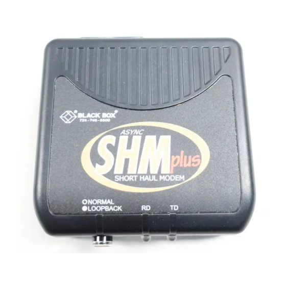
Short-Haul Modem B (SHM-B)
Plus Async
CUSTOMER SUPPORT INFORMATION
Order toll-free in the U.S.: Call 877-877-BBOX (outside U.S. call 724-746-5500)
FREE technical support 24 hours a day, 7 days a week: Call 724-746-5500 or fax 724-746-0746
Mailing address: Black Box Corporation, 1000 Park Drive, Lawrence, PA 15055-1018
Web site: www.blackbox.com • E-mail: info@blackbox.com
Advertisement
Table of Contents

Related Manuals for Black Box SHM-B Plus Async Series


Summary of Contents for Black Box SHM-B Plus Async Series
- Page 1 Order toll-free in the U.S.: Call 877-877-BBOX (outside U.S. call 724-746-5500) FREE technical support 24 hours a day, 7 days a week: Call 724-746-5500 or fax 724-746-0746 Mailing address: Black Box Corporation, 1000 Park Drive, Lawrence, PA 15055-1018 Web site: www.blackbox.com • E-mail: info@blackbox.com...
- Page 2 Industrie Canada. TRADEMARKS USED IN THIS MANUAL BLACK BOX and the logo are registered trademarks of Black Box Corporation. Any other trademarks mentioned in this manual are acknowledged to be the property of the trademark owners.
- Page 3 SHM-B PLUS ASYNC NORMAS OFICIALES MEXICANAS (NOM) ELECTRICAL SAFETY STATEMENT INSTRUCCIONES DE SEGURIDAD 1. Todas las instrucciones de seguridad y operación deberán ser leídas antes de que el aparato eléctrico sea operado. 2. Las instrucciones de seguridad y operación deberán ser guardadas para referencia futura.
- Page 4 NOM STATEMENT 10. El equipo eléctrico deber ser situado fuera del alcance de fuentes de calor como radiadores, registros de calor, estufas u otros aparatos (incluyendo amplificadores) que producen calor. 11. El aparato eléctrico deberá ser connectado a una fuente de poder sólo del tipo descrito en el instructivo de operación, o como se indique en el aparato.
-
Page 5: Table Of Contents
SHM-B PLUS ASYNC Contents Chapter Page 1. Specifications .............. 5 2. Introduction ............... 8 3. Installation and Configuration ........9 3.1 Making the Four-Wire Connection ....9 3.2 Making the RS-232 Connections ...... 12 3.3 Setting the DTE/DCE Switch (S1) ....13 3.4 Setting the Flow-Control Switch (S3) .... -
Page 6: Specifications
CHAPTER 1: Specifications 1. Specifications Data Rate and Maximum Distance: Data Rate (bps) AWG (mm) 24 (0.5) 26 (0.4) Distance in miles 115,200 57,600 38,400 19,200 9600 4800 2400 1200 NOTE: The above specifications are valid for 24- or 26-AWG unshielded twisted-pair telephone cable insulated by polyethylene with a mutual capacitance of 0.083 pF/mile (0.52 pF/km). - Page 7 SHM-B PLUS ASYNC Equipment Interface: TIA/EIA RS-232/ITU V.24 interface with a hardware handshake (selected through use of an external switch); Data Carrier Detect (DCD) true (high) indicates operating short-haul modem at the remote end of the loop; interface is switch-selectable for DTE/DCE configuration (pins 2 and 3 reversed, pins 4 and 5 reversed with pin 8, pin 6 reversed with pin 20) Connectors: (1) DB25 female, (1) 4-screw terminal...
- Page 8 CHAPTER 1: Specifications Power: From external power supply (no more than 16 Vrms is present in unit): Input (ME800A-PLUS): 115 VAC ±10%, 60 Hz, 5 watts (12 watts maximum); Input (ME800AE-PLUS): 230 VAC ±10%, 50/60 Hz; Output (both models): 17 VAC, 700 mA Size: 1.3"H x 4"W x 4.2"D (3.3 x 10.2 x 10.7 cm) Weight: 1.4 lb.
-
Page 9: Introduction
SHM-B PLUS ASYNC 2. Introduction The Short-Haul Modem Model B Plus Async (SHM-B Plus Async) is a standalone asynchronous full-duplex 4-wire line driver/receiver which allows two TIA/EIA RS-232 devices to communicate at distances of up to 4.8 miles (7.7 km) or at data rates up to 115.2 kbps. In addition to the transmitter and receiver circuits, the SHM-B Plus Async includes RS-232 control-line interfaces, status-monitor LEDs, and a loopback switch. -
Page 10: Installation And Configuration
CHAPTER 3: Installation and Configuration 3. Installation and Configuration You can install and configure the SHM-B Plus Async in three basic steps: making the four-wire connections, making the RS-232 connection, and setting the switches. 3.1 Making the Four-Wire Connections Connect a pair of SHM-B Plus Async modems to each other through either their terminal blocks or their RJ-11 connectors. - Page 11 SHM-B PLUS ASYNC Figure 3-1. Bottom view. Pair 1 Pair 2 SHM #2 SHM #1 Figure 3-2. Wiring diagram—terminal block.
- Page 12 CHAPTER 3: Installation and Configuration b) RJ-11 JACK: 1. Connect pairs of modems using a crossover RJ-11 cable (refer to Figure 3-3). A crossover cable has the RJ-11 tabs on the same side of the cable. 2. Insert the RJ-11 cable into the RJ-11 jack on the modem.
-
Page 13: Making The Rs-232 Connections
SHM-B PLUS ASYNC 3.2 Making the RS-232 Connection Connect the SHM-B Plus Async to your computer or terminal with a standard RS-232 cable that has a DB25 male connector on the SHM-B end. Refer to your equipment’s installation manual if you need information on the exact RS-232 signals required for your equipment. -
Page 14: Setting The Dte/Dce Switch (S1)
CHAPTER 3: Installation and Configuration 3.3 Setting the DTE/DCE Switch (S1) Refer to Figure 3-1. Switch S1 is used to reverse the TD, RD, and hardware flow-control lines on the SHM-B Plus Async’s RS-232 interface. This eliminates the need to swap these signals in your RS-232 cables. - Page 15 SHM-B PLUS ASYNC Table 3-2. The SHM-B’s RS-232 DCE pinout. PIN NUMBER SIGNAL NAME DIRECTION Shield (SHD) ————— Transmitted Data (TD)* To DCE Received Data (RD)* From DCE Request to Send (RTS)* To DCE Clear to Send (CTS)* From DCE Data Set Ready (DSR)* From DCE Signal Ground (SGND)
-
Page 16: Setting The Flow-Control Switch (S3)
CHAPTER 3: Installation and Configuration 3.4 Setting the Flow-Control Switch (S3) You can set the SHM-B Plus Async to use software or hardware or software flow control in order to make it compatible with a broad range of equipment. RS-232C H (RTS/DTR C TANDARD ANDSHAKING... - Page 17 SHM-B PLUS ASYNC Because DTR, DSR, RTS, and CTS are tied together internally, dropping any one of these four signals to a negative state will also drop DCD on the remote side to a negative state. DCD will also go LOW if the remote SHM-B is powered down, or if the twisted-pair wire is broken.
-
Page 18: Operation
CHAPTER 4: Operation 4. Operation After completing the wiring and configuration procedure and connecting the SHM-B Plus Async to your equipment, plug its wall transformer into the SHM-B and a working AC outlet. Check the SHM-B operation at both ends of the link by pressing the LOOPBACK switch, S2, first on one modem and then on the other. - Page 19 SHM-B PLUS ASYNC When in loopback mode, the switch-button indicator will appear white. If a CRT terminal is connected to the SHM-B, typing characters on the keyboard should result in the same characters appearing on the CRT screen. If no characters appear, check your RS-232 connections and the setting of S1.
-
Page 20: Troubleshooting
CHAPTER 5: Troubleshooting 5. Troubleshooting The following information will help you troubleshoot your SHM-B Plus Async installation if problems develop. If your particular situation isn’t listed here, call Technical Support for assistance. Have ready a description of the problem with your installation, the makes and models of the attached equipment, your equipment’s DTE/DCE configuration and flow-control type (hardware or software), your RS-232 cable pinouts,... - Page 21 SHM-B PLUS ASYNC SYMPTOM: No data transfer in one or both directions (to, from, or to-and-from the SHM-B Plus Async). 1. Monitor the TD LED on the sending-end modem while sending data. The light should flash red/green. If not, check the DCE/DTE switch on that unit. Once you get a TD LED flashing on that unit, the RD LED should simultaneously flash on the other SHM-B unit.
- Page 22 CHAPTER 5: Troubleshooting 5. If pin 8 (Data Carrier Detect) is low, this indicates: • a defective transmission line or connection, • a defective remote SHM-B, or • a remote SHM-B without power. SYMPTOM: TD and RD LEDs indicate data activity, but data communication doesn’t exist.
- Page 23 SHM-B PLUS ASYNC 3. Wire the SHM-B units back-to-back, eliminating the twisted-pair; see if you still have errors. • If you do have errors, then test each SHM-B individually in the following way: loop back one SHM-B’s Transmit to its own Receive by using two short pieces of wire.
- Page 24 CHAPTER 5: Troubleshooting 3. Check the path of your four-wire circuit for potential sources of interference (fluorescent lighting, electrical motors, etc.). Such sources of electrical noise can provide an environment in which unwanted signals are induced onto your four-wire circuit. Also, check to see if an adjacent four-wire cable carrying a separate data stream is creating crosstalk.
- Page 25 NOTES...
- Page 26 © Copyright 2002. Black Box Corporation. All rights reserved. 1000 Park Drive • Lawrence, PA 15055-1018 • 724-746-5500 • Fax 724-746-0746...
Need help?
Do you have a question about the SHM-B Plus Async Series and is the answer not in the manual?
Questions and answers