Table of Contents
Advertisement
Quick Links
Advertisement
Table of Contents

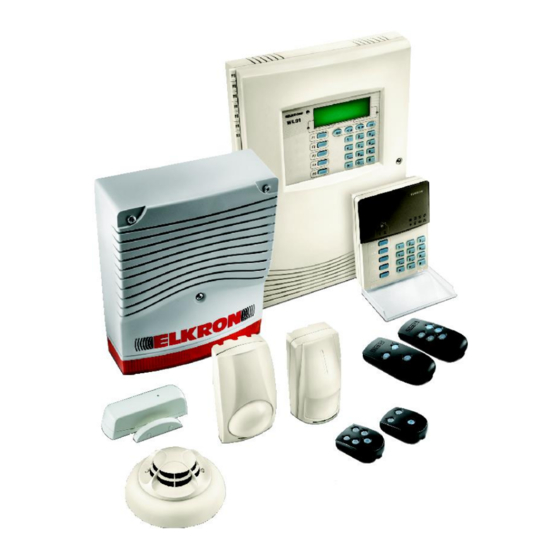
Related Manuals for Elkron wl31


Summary of Contents for Elkron wl31
- Page 1 WL31 WL31TG Bidirectional wireless system 0681 IS0244-AA 1/32 WL31...
- Page 2 All information included in this document has been collected and carefully verified; nevertheless Elkron S.p.A. can not be held responsible for possible mistakes and omissions. Elkron S.p.A. reserves the right to modify or improve at any time and without notice the products described in this manual.
-
Page 3: Table Of Contents
SETTING ..................................19 SETTINGS [3]................................19 SETTINGS - EXCLUDE/INCLUDE [30]........................19 SETTINGS - TIME AND DATE [31] .........................19 TIME AND DATE - SET TIME [310].........................20 TIME AND DATE - SET DATE [311]........................20 SETTING - LANGUAGE [32] ...........................20 LANGUAGE - SELECT LANGUAGE [320]......................20 3/32 WL31... - Page 4 7.2 FUNCTIONS ALLOCATED TO THE “FUNCTION” KEY OF THE CENTRAL UNIT KEYBOARDS ....24 7.2.1 REMOTE COMMUTATION ........................25 8.0 YOUR SYSTEM..............................26 8.1 FUNCTIONS ALLOCATED TO THE “FUNCTION” KEY OF THE CENTRAL UNIT KEYBOARDS ....26 8.2 FUNCTIONS ALLOCATED TO THE “FUNCTION” KEY OF THE REMOTE CONTROLS AND OF THE REMOTE KEYBOARDS............................27 4/32 WL31...
-
Page 5: Description Of The Central Unit Keyboard
1.1 FUNCTION KEYS PERSONALIZING LABELS Deactivation Service Activation Fire alarm Toggle (status commutation) Panic alarm Emergency NOT USED 5/32 WL31... -
Page 6: Meaning Of The Icons
This is on to signal that the main board is connected with a PC. REMOTE MANAGEMENT FROM PSTN LINE MEMORY (edition WL31TG) This is on to record an in-coming call (on the PSTN line) for a MODEM connection (Fast Link). 6/32 WL31... -
Page 7: Information On The System's Status
At the end of the visualization, if the event is not present anymore, the icon will be cancelled (memory reset). The icons which memorize events which depend on the system’s status will be automatically cancelled at the next activation. 7/32 WL31... -
Page 8: Function Keys Programming
Using this command it is possible to manage, for example, the opening of SERVICE COMMAND an automatic gate or the opening of a horizontally pivoted garage door The five function keys (F1…F5) can be personalized using the specific labels which should be positioned under the supplied transparent keys cover. 8/32 WL31... -
Page 9: Description Of The Remote Keyboard
This is useful to reduce consumption and extend the batteries’ life. These show the system status. System Status LEDs LED on in a GREEN colour = DEACTIVATED SECTOR LED on in a RED colour = ACTIVATED SECTOR 9/32 WL31... -
Page 10: Programmability Of The Remote Keyboard Function Keys
Using this command it is possible to manage, for example, the opening of SERVICE COMMAND an automatic gate or the opening of a horizontally pivoted garage door. The five function keys (F1…F5) can be personalized using the specific labels to be positioned under the supplied transparent keys cover. 10/32 WL31... -
Page 11: Remote Control Description
LONG PRESSURE: Activation of service exit 1 KEY 3 SHORT PRESSURE: Activation of service exit 1 LONG PRESSURE: Activation of service exit 2 KEY 4 SHORT PRESSURE: Activation of service exit 2 SHORT PRESSURE: System status request KEY 5 LONG PRESSURE: System status request 11/32 WL31... -
Page 12: Functions Which Can Be Allocated To The Function Keys
Open the remote control, remove from the plastic sheet supplied the required label, insert it in its specific location on the cover, as shown by the figure and close the remote control again. 12/32 WL31... -
Page 13: Using The System
A = press the key to totally activate the system R = your system is now totally activated (Remember that in the factory setting there is only one sector) 13/32 WL31... -
Page 14: Deactivating The System From The Central Unit Keyboard
A = press the to totally deactivate the system; R = your system has been totally deactivated (Remember that in the factory setting there is only one sector): 14/32 WL31... -
Page 15: Activating The System From A Remote Keyboard
(all red = system activated); A = press the F2 key to totally deactivate the system; R = Your system is now totally deactivated (Remember that in the factory setting there is only one sector): GREEN 15/32 WL31... -
Page 16: Access To The Central Unit Menu
It moves to the following data in a sequence of data to be input 5.3 SYSTEM ACCESS CODE To manage the WL31 system up to 18 different codes can be used: 1 MASTER, 1 TECHNICIAN, 16 USERS. In this manual, for each menu item, the codes which can access it are shown. -
Page 17: How To Access The Cascading Menu
ESC key. To exit from all menus press the ESC key many times until the display shows the «((( ELKRON )))» message. 5.5 HOW TO QUICKLY ACCESS A MENU ITEM... -
Page 18: Functions
Confirm your choice by pressing the OK key. EVENT MEMORY EVENT MEMORY [2] Purpose: This enables you to look through the last 500 registered events on the WL31 central unit display. For every event the following is supplied: • The consecutive number in the list, •... -
Page 19: Setting
This enables you to set the current day, month and year on the system. These will then be used by the EVENT MEMORY. The information relating to the time and date is constantly shown on the display, in the pre-set format and alternated. Submenu Fast code Time and date - Set time Time and date - Set date 19/32 WL31... -
Page 20: Time And Date - Set Time [310]
2. Select the user you are interested in and press OK to confirm. 3. Using the keys scroll the «Assoc. sectors» or «Nominate user» sub-menus and confirm by pressing the OK key. 20/32 WL31... -
Page 21: Settings - Control Delay [35]
ENGAGING - TIME CONTROLS [42] Purpose: This enables and disables the time programmer management. How to do it: 1. Press the OK key. 2. Using the keys, select the «Activated» or «Deactivated» function and press the OK key to confirm it. 21/32 WL31... -
Page 22: Engaging - Advanced Settings [43]
• MM30WL magnetic contact sensor (including the relating auxiliary Inputs), • WL31 central unit wire inputs. How to do it: 1. Start the test by pressing the OK key; the display shows the “test underway….” Message. 2. Afterwards stimulate each input (walk through the area protected by volume sensors, open doors and windows equipped with opening detectors, etc.): the activation of the relating red LED indicates that the alarm has been... -
Page 23: Test - Fire Det. [51]
WL31 central unit display confirms that it has been correctly received. 3. Once the inputs’ stimulation phase is finished, press the OK key: the display will show “TEST FAILED”, which contains the list of devices programmed as theft that failed to reply. -
Page 24: Telephonic Trx
30 = deactivation of alarm system • 511 = Activation of cable output 1 • 510 = Deactivation of cable output 1 • 521 = Activation of cable output 2 • 520 = Deactivation of cable output 2 24/32 WL31... -
Page 25: Remote Commutation
0,5 s Received 1: WIRE OUTPUT 1 2: WIRE OUTPUT 2 bip-bip 0,5 s + ASSOCIATED VOICE command complete Send the control: MESSAGE 1: ACTIVATE 0: DEACTIVATE Error: command not bip-bip-bip-bip-bip-bip performed 25/32 WL31... -
Page 26: Your System
The following are some tables where you will be able to copy the divisions and the allocations of your alarm system as well as the functions of the remote control and keyboard keys. SECTOR 3 SECTOR 4 SECTOR 1 SECTOR 2 8.1 FUNCTIONS ALLOCATED TO THE “FUNCTION” KEY OF THE CENTRAL UNIT KEYBOARDS 26/32 WL31... -
Page 27: Functions Allocated To The "Function" Key Of The Remote Controls And Of The Remote Keyboards
LONG PRESSURE _____________________ SHORT PRESSURE ____________________ SHORT PRESSURE ____________________ LONG PRESSURE _____________________ LONG PRESSURE _____________________ SHORT PRESSURE ____________________ SHORT PRESSURE ____________________ LONG PRESSURE _____________________ LONG PRESSURE _____________________ SHORT PRESSURE ____________________ LONG PRESSURE _____________________ SHORT PRESSURE ____________________ LONG PRESSURE _____________________ 27/32 WL31... - Page 28 LONG PRESSURE _____________________ SHORT PRESSURE ____________________ SHORT PRESSURE ____________________ LONG PRESSURE _____________________ LONG PRESSURE _____________________ SHORT PRESSURE ____________________ SHORT PRESSURE ____________________ LONG PRESSURE _____________________ LONG PRESSURE _____________________ SHORT PRESSURE ____________________ LONG PRESSURE _____________________ SHORT PRESSURE ____________________ LONG PRESSURE _____________________ 28/32 WL31...
- Page 29 LONG PRESSURE _____________________ SHORT PRESSURE ____________________ SHORT PRESSURE ____________________ LONG PRESSURE _____________________ LONG PRESSURE _____________________ SHORT PRESSURE ____________________ PRESSIONE BREVE ___________________ LONG PRESSURE _____________________ LONG PRESSURE _____________________ PRESSIONE BREVE ___________________ LONG PRESSURE _____________________ PRESSIONE BREVE ___________________ LONG PRESSURE _____________________ 29/32 WL31...
- Page 30 30/32 WL31...
- Page 31 31/32 WL31...
- Page 32 ELKRON S.p.A. Via G. Carducci, 3 – 10092 Beinasco (TO) – ITALY 32/32 WL31 Tel. +39 (0)11.3986711 – Fax +39 (0)11.3499434 www.elkron.it - mailto: info@elkron.it...
Need help?
Do you have a question about the wl31 and is the answer not in the manual?
Questions and answers