Table of Contents
Advertisement
Quick Links
•
GSM and GPRS
•
Voice / Fax / SMS and Data
•
Quad Band 850 / 900 / 1800 1900 MHz
•
Accepts Standard SIM Card
•
Miniature size 88 x 60 x 26mm
•
Can Be Used On Standard GSM Network
•
RS232 Interface
•
One user programmable input/Output Port
•
GSM100T: TCP/IP stack available for data and
internet
•
AT command set:
GSM 07.05 and 07.07 and WAVECOM
•
GPRS Class B Class 10:
36Kbps download / 24Kbps upload
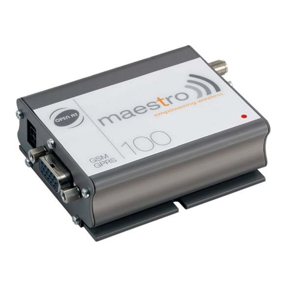
Compact "Plug And Play" Quad band GSM modems can be directly connected to the serial port of a desktop or
notebook computer through the RS232 interface. A standard SIM card can be inserted in the integral card-holder
within the metal enclosure.
The modems' metal casing makes it an appropriate solution for tough industrial applications such as Telemetry,
Wireless Local Loop (payphones) or as part of a fleet management system. The small size makes it simple to
integrate in a space constraint environment. The modem is supplied with power cable. Other accessories available
are an antenna (with 1m coax cable), RS232 connecting cable with Telephone interface, DIN Rail mounting adaptor
and power supply unit.
About GPRS: GPRS stands for General Packet Radio Services. The user can remain "ON" all the time and the
data communication speed rivals that of a cable modem.
Ordering Information
Part No
GSM100
GSM100T
GSM20-ANT
GSM20-CAB232
GSM20-DINRL
GSM20-PSU
DS100-1 May '07
GSM & GPRS Modem
GSM Quad Band Modem, GPRS Class 10
As GSM100 with Additional TCP/IP Stack
Antenna with flying lead and connector
Power Supply (12Vdc to 110-240Vac)
www.rfsolutions.co.uk
Description
RS232 Cable Interface to PC
DIN Rail Mount Bracket
©2007 REG No 277 4001, ENGLAND.
Advertisement
Table of Contents

Related Manuals for Maestro GSM100


Summary of Contents for Maestro GSM100
- Page 1 Ordering Information Part No Description GSM100 GSM Quad Band Modem, GPRS Class 10 GSM100T As GSM100 with Additional TCP/IP Stack GSM20-ANT Antenna with flying lead and connector GSM20-CAB232 RS232 Cable Interface to PC GSM20-DINRL DIN Rail Mount Bracket...
-
Page 2: Table Of Contents
GSM & GPRS Modem CONTENTS SAFETY PRECUTIONS CHAPTER 1 INTRODUCTION CHAPTER 2 INSTALLATION CHAPTER 3 WORKING WITH MAESTRO 100 CHAPTER 4 SPECIFICATION CHAPTER 5 APPENDIX CHAPTER 6 TROUBLESHOOTING ©2007 REG No 277 4001, ENGLAND. Page 1 DS100-1 May ’07 www.rfsolutions.co.uk... -
Page 3: Safety Precutions
GSM & GPRS Modem SAFETY PRECUTIONS The modem generates radio frequency (RF) power. When using the modem care must be taken on safety issues related to RF interference as well as regulations of RF equipment. Do not use your phone in aircraft, hospitals, petrol stations or in places where using GSM products is prohibited. -
Page 4: Chapter 1 Introduction
CHAPTER 1 INTRODUCTION Maestro 100 is a ready-to-use GSM modem for voice, data, fax and SMS services. It also supports GPRS Class 10 for hi-speed data transfer. Maestro 100 can be easily controlled by using AT command for all kinds of operations. With standard 9-pin RS232 port and telephone-like audio plug (via optional cable) the Maestro 100 can be set up with minimal effort. - Page 5 GSM & GPRS Modem 1.2.3. 15-PIN D-SUB Female connector (RS232 / Audio) The connector provides serial link and audio link to the modem. Pin number Name EIA designation Type Note Data Carrier Detect Output Transmit Data Input BOOT Input Not used MICROPHONE (+) Input With 2V DC bias...
-
Page 6: Optional Accessories
GSM & GPRS Modem A cable, included in the package shall be used for power supply connection: 5-32V DC Supply Stripped wire Connector Micro-Fit 3.0 Fuse holder Fuse rating : Parameters Typical Remark I/O In LOW voltage 0.5V I/O In HIGH voltage I/O out max. - Page 7 GSM & GPRS Modem ‘Y’ cable Direct connection with standard 9-pin RS-232 port (DTE) Direct connection with common handset of telephone for voice call Shielded cable Pin Assignment Sub-D 15 Sub-D 9 Plug Cable length 1.1m (w/ connector) (male) (female) 4P4C Sub-D 9 pin 4p4c plug...
-
Page 8: Chapter 2 Installation
GSM & GPRS Modem CHAPTER 2 INSTALLATION 2.1 Mounting the modem Use 2 pcs of M3 screw to mount the modem When using optional DIN rail mount please refer to document “Installation of DIN rail mount” Screw mounting slot Bottom view 2.2 Installing the SIM card Use a ball pen or paper clip to press the SIM holder eject button. -
Page 9: Connect The Modem To External Device
Note : The modem CANNOT be connected to the ‘Line’ jack of a landline telephone directly. Connection example using optional ‘Y’ cable: 4p4c Handset of phone Maestro Sub-D 15 pin DB-9 RS-232 port of PC 2.5 Connecting the DC power supply Connect the open ending of the included power cord to a DC supply. -
Page 10: Working With Maestro 100
GSM & GPRS Modem CHAPTER 3 WORKING WITH MAESTRO 100 3.1. Checking the modem (using Microsoft Windows XP HyperTerminal as example) 3.1.1. On the first time power-up you can use a terminal software to communicate with the modem through an RS-232 serial port. Following example is using the HyperTerminal in Windows XP . - Page 11 GSM & GPRS Modem 3.1.3. Choose the correct Com port and baud rate settings (9600bps for Eco; 115200bps for others, 8bits, no parity bit, 1 stop bit). 3.1.4. modem On the terminal screen, type “AT” to check the “OK” response from the ©2007 REG No 277 4001, ENGLAND.
-
Page 12: Basic Operation
GSM & GPRS Modem 3.2. Basic Operation : Followings are examples of some AT commands. Please refer to the AT Command guide for a full description. Note : Issue AT+CMEE=1 to have extended error code (+CME ERROR) Description AT commands Modem response Comments Network Registration AT+CREG? -
Page 13: Chapter 4 Specification
GSM & GPRS Modem CHAPTER 4 SPECIFICATION Bands 850 / 900 / 1800 / 1900 Mhz Support Data, SMS, Voice and Fax Max Power Output: 2W(900Mhz), 1W(1800Mhz) Group 3 FAX support (Class 1 and 2) GPRS Class B Class 10 (4Rx+1Tx or 3Rx+2Tx) at maximum speed.* SimToolKit Class 2 AT command set (GSM 07.05, GSM 07.07 and WAVECOM proprietary) * Note : Available slot for GPRS connection is network dependent. -
Page 14: Appendix
GSM & GPRS Modem CHAPTER 5 APPENDIX 5.1 Factory settings The modem has the following factory settings. Please refer to the AT command document for the meaning of each setting. Related AT commands Factory Settings Description AT+IPR 115200 (9600 for Eco) DTE-DCE data rate AT+IFC DTE-DCE flow control... -
Page 15: Chapter 6 Troubleshooting
6.3 The modem does not response to the terminal program Check if the RS-232 cable has been connected properly Check if your program has proper setting. Factory setting of the modem is: 115200bps (9600bps for Maestro 100 Eco) 8 data bits no parity bit 1 stop bit 6.4 No voice could be heard for the modem’s speaker output when a call is...
Need help?
Do you have a question about the GSM100 and is the answer not in the manual?
Questions and answers