Table of Contents
Advertisement
Quick Links
INSTRUCTION MANUAL
INSTALLATION, COMMISSIONING & SERVICING
FLOOR STANDING EXTERNAL OIL FIRED CONDENSING BOILER USING
BALANCED FLUE SYSTEM
GREENSTAR CAMRAY EXTERNAL &
EXTERNAL SYSTEM 12/18, 18/25, 25/32
FOR FULLY PUMPED OPEN VENT OR SEALED CENTRAL HEATING SYSTEM AND DOMESTIC HOT
WATER CYLINDERS
THE APPLIANCE IS FOR USE WITH KEROSENE (28 SECOND
OIL) ONLY
GB
Advertisement
Table of Contents

Related Manuals for Worcester GREENSTAR CAMRAY EXTERNAL


Summary of Contents for Worcester GREENSTAR CAMRAY EXTERNAL
- Page 1 INSTRUCTION MANUAL INSTALLATION, COMMISSIONING & SERVICING FLOOR STANDING EXTERNAL OIL FIRED CONDENSING BOILER USING BALANCED FLUE SYSTEM GREENSTAR CAMRAY EXTERNAL & EXTERNAL SYSTEM 12/18, 18/25, 25/32 FOR FULLY PUMPED OPEN VENT OR SEALED CENTRAL HEATING SYSTEM AND DOMESTIC HOT WATER CYLINDERS...
- Page 2 LABC will then arrange regular inspection visits during the work to ensure that the installation complies with the regulations. IF YOU ARE IN ANY DOUBT CONTACT THE WORCESTER TECHNICAL HELPLINE. DISTANCE LEARNING AND TRAINING COURSES ARE AVAILABLE FROM WORCESTER. PLEASE LEAVE THESE INSTRUCTIONS WITH THE COMPLETED COMMISSIONING FORM AND THE USER MANUAL WITH THE OWNER OR WITH THE APPLIANCE AFTER INSTALLATION OR SERVICING.
-
Page 3: Table Of Contents
FAULT FINDING & DIAGNOSIS FAULT FINDING 52-54 FAULT FINDING LOGIC FOR 535 SE/LD RDB CONTROL BOX COMBUSTION RECORD SERVICE INTERVAL RECORD NOTES INSTALLATION & SERVICING INSTRUCTIONS FOR WORCESTER GREENSTAR CAMRAY EXTERNAL & CONTENTS EXTERNAL SYSTEM 12/18-18/25-25/32 8 716 115 667a (05.2009) -
Page 4: Safety Precautions And Installation Regulations
The Control of Pollution (Oil) Regulations. OFTEC Standards. Where no specific instruction is given, reference should be made to the relevant codes of practice. INSTALLATION & SERVICING INSTRUCTIONS FOR WORCESTER GREENSTAR CAMRAY EXTERNAL & SAFETY PRECAUTIONS EXTERNAL SYSTEM 12/18-18/25-25/32 8 716 115 667a (05.2009) -
Page 5: General Information
Users Instructions ..................1 Hardware Pack....................1 100mm Ø Services Duct................1 Condensate Trap Kit..................1 Warranty Return Envelope ................1 Cabinet Key.......................1 INSTALLATION & SERVICING INSTRUCTIONS FOR WORCESTER GREENSTAR CAMRAY EXTERNAL & GENERAL INFORMATION EXTERNAL SYSTEM 12/18-18/25-25/32 8 716 115 667a (05.2009) -
Page 6: Technical Data
Weight (excluding packaging) External System Expansion vessel (External System only) litres Emissions class for NOx and CO class Typical NOx emission figures mg/kWhr INSTALLATION & SERVICING INSTRUCTIONS FOR WORCESTER GREENSTAR CAMRAY EXTERNAL & TECHNICAL DATA EXTERNAL SYSTEM 12/18-18/25-25/32 8 716 115 667a (05.2009) -
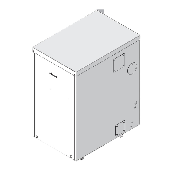
Page 7: Layout & Components Camray External
31 FLUE GAS SAMPLING POINT 32 MODE SWITCH 33 BOILER OVERHEAT RESET BUTTON 34 FLUE OVERHEAT RESET BUTTON 35 TEMPERATURE CONTROL KNOB INSTALLATION & SERVICING INSTRUCTIONS FOR WORCESTER GREENSTAR CAMRAY EXTERNAL & LAYOUT & COMPONENTS EXTERNAL SYSTEM 12/18-18/25-25/32 8 716 115 667a (05.2009) -
Page 8: Layout & Components Camray External System
36 MODE SWITCH 37 SYSTEM PRESSURE GUAGE 38 BOILER OVERHEAT RESET BUTTON 39 FLUE OVERHEAT RESET BUTTON 40 TEMPERATURE CONTROL KNOB INSTALLATION & SERVICING INSTRUCTIONS FOR WORCESTER GREENSTAR CAMRAY EXTERNAL & LAYOUT & COMPONENTS EXTERNAL SYSTEM 12/18-18/25-25/32 8 716 115 667a (05.2009) -
Page 9: Cleaning Primary Systems
Drain and thoroughly flush the system to remove the flushing agent and any debris. Refil with clean water and inhibitor to manufacturers instructions. INSTALLATION & SERVICING INSTRUCTIONS FOR WORCESTER GREENSTAR CAMRAY EXTERNAL & CLEANING PRIMARY SYSTEMS EXTERNAL SYSTEM 12/18-18/25-25/32 8 716 115 667a (05.2009) -
Page 10: Mains Supply
• Any system connected to the boiler must not have a separate electrical supply. INSTALLATION & SERVICING INSTRUCTIONS FOR WORCESTER GREENSTAR CAMRAY EXTERNAL & MAINS SUPPLY EXTERNAL SYSTEM 12/18-18/25-25/32 8 716 115 667a (05.2009) -
Page 11: Oil Supply
The table and illustration above is a guide only and does not in any way override the de- as the sole fire protection device. aerator manufacturers instructions. INSTALLATION & SERVICING INSTRUCTIONS FOR WORCESTER GREENSTAR CAMRAY EXTERNAL & OIL SUPPLY EXTERNAL SYSTEM 12/18-18/25-25/32... -
Page 12: Water Systems & Pipework
• A pressure gauge (G), 3 bar minimum is fitted to the appliance • An automatic air vent (N) must be fitted. INSTALLATION & SERVICING INSTRUCTIONS FOR WORCESTER GREENSTAR CAMRAY EXTERNAL & WATER SYSTEMS & PIPEWORK EXTERNAL SYSTEM 12/18-18/25-25/32 8 716 115 667a (05.2009) -
Page 13: Water Systems & Pipework
Auto air vent Non return 1000mm above valve the highest point of the system Stop cock Fill Point INSTALLATION & SERVICING INSTRUCTIONS FOR WORCESTER GREENSTAR CAMRAY EXTERNAL & WATER SYSTEMS & PIPEWORK EXTERNAL SYSTEM 12/18-18/25-25/32 8 716 115 667a (05.2009) -
Page 14: Condensate Pipework
H - Drainage holes 50mm from base of tube (12mm Ø at 25mm centres) facing away from building. Limestone chippings. INSTALLATION & SERVICING INSTRUCTIONS FOR WORCESTER GREENSTAR CAMRAY EXTERNAL & CONDENSATE PIPEWORK EXTERNAL SYSTEM 12/18-18/25-25/32 8 716 115 667a (05.2009) -
Page 15: Pressure Relief Pipework
(as shown) to help prevent freezing. External boiler casing. Drain pipe. Hard standing. Typical pressure relief drain pipe routing. INSTALLATION & SERVICING INSTRUCTIONS FOR WORCESTER GREENSTAR CAMRAY EXTERNAL & PRESSURE RELIEF PIPEWORK EXTERNAL SYSTEM 12/18-18/25-25/32 8 716 115 667a (05.2009) -
Page 16: Boiler Location & Clearances
FRONT 600mm 50mm 50mm 2500mm 10mm 10mm 2500mm Plan Plan view view FRONT FRONT 600mm 600mm INSTALLATION & SERVICING INSTRUCTIONS FOR WORCESTER GREENSTAR CAMRAY EXTERNAL & BOILER LOCATION & EXTERNAL SYSTEM 12/18-18/25-25/32 8 716 115 667a (05.2009) CLEARANCES... -
Page 17: Low Level Flue Terminal Positions
750mm wide. boundary C, D boundary INSTALLATION & SERVICING INSTRUCTIONS FOR WORCESTER GREENSTAR CAMRAY EXTERNAL & CABINET MOUNTED LOW LEVEL EXTERNAL SYSTEM 12/18-18/25-25/32 8 716 115 667a (05.2009) TERMINAL... -
Page 18: High Level Flue Terminal Positions
• **Minimum distance of the flue terminal to a facing wall, fence, building or property boundary is 2500mm. Flat roof boundary Pitched roof C, D boundary INSTALLATION & SERVICING INSTRUCTIONS FOR WORCESTER GREENSTAR CAMRAY EXTERNAL & HIGH LEVEL TERMINAL POSITIONS EXTERNAL SYSTEM 12/18-18/25-25/32 8 716 115 667a (05.2009) -
Page 19: Balanced Flue Options
* Rear exit only. ** Horizontal flue runs should be kept as short as possible. Vertical terminal (side outlet) INSTALLATION & SERVICING INSTRUCTIONS FOR WORCESTER GREENSTAR CAMRAY EXTERNAL & BALANCED EXTERNAL OILFIT EXTERNAL SYSTEM 12/18-18/25-25/32 8 716 115 667a (05.2009) - Page 20 Part No. 7 716 190 050 FRONT RIGHT HAND FLUE OUTLET A + B + C Plan view FRONT INSTALLATION & SERVICING INSTRUCTIONS FOR WORCESTER GREENSTAR CAMRAY EXTERNAL & CABINET MOUNTED BALANCED EXTERNAL SYSTEM 12/18-18/25-25/32 8 716 115 667a (05.2009) HORIZONTAL FLUE OPTIONS...
-
Page 21: Unpacking The Boiler
Lift carton up and away from the boiler. Remove the plastic bag from the boiler and place safely aside. INSTALLATION & SERVICING INSTRUCTIONS FOR WORCESTER GREENSTAR CAMRAY EXTERNAL & UNPACKING THE BOILER EXTERNAL SYSTEM 12/18-18/25-25/32 8 716 115 667a (05.2009) -
Page 22: Pipework & Flue Positions
105 94 RIGHT HAND SIDE Fire valve capillary & drain access Flue Services Condensate 124 90 LEFT HAND SIDE INSTALLATION & SERVICING INSTRUCTIONS FOR WORCESTER GREENSTAR CAMRAY EXTERNAL & PIPEWORK & FLUE POSITIONS EXTERNAL SYSTEM 12/18-18/25-25/32 8 716 115 667a (05.2009) -
Page 23: Boiler Installation
100mm sealing ring where the duct enters the casing and seal the joint to the exterior wall and inside the cabinet with a suitable sealant. INSTALLATION & SERVICING INSTRUCTIONS FOR WORCESTER GREENSTAR CAMRAY EXTERNAL & BOILER INSTALLATION EXTERNAL SYSTEM 12/18-18/25-25/32 8 716 115 667a (05.2009) -
Page 24: Flue Installation
(if necessary). Refer to the flue manual supplied with the flue kit for flue installation. INSTALLATION & SERVICING INSTRUCTIONS FOR WORCESTER GREENSTAR CAMRAY EXTERNAL & FLUE INSTALLATION EXTERNAL SYSTEM 12/18-18/25-25/32 8 716 115 667a (05.2009) -
Page 25: Combustion Chamber
( J ). Check that all the baffles (K) and baffle retainer (L) are correctly fitted to the secondary heat exchanger. INSTALLATION & SERVICING INSTRUCTIONS FOR WORCESTER GREENSTAR CAMRAY EXTERNAL & COMBUSTION CHAMBER EXTERNAL SYSTEM 12/18-18/25-25/32 8 716 115 667a (05.2009) -
Page 26: Pipework Connections
Rotate the cover plate and seal so it does not cover the capillary, then secure with the screws provided. INSTALLATION & SERVICING INSTRUCTIONS FOR WORCESTER GREENSTAR CAMRAY EXTERNAL & PIPEWORK CONNECTIONS EXTERNAL SYSTEM 12/18-18/25-25/32 8 716 115 667a (05.2009) - Page 27 IMPORTANT: Insulate all external condensate pipework or run in 32mm pipework to prevent freezing. 50mm (min.) 500ml INSTALLATION & SERVICING INSTRUCTIONS FOR WORCESTER GREENSTAR CAMRAY EXTERNAL & PIPEWORK CONNECTIONS EXTERNAL SYSTEM 12/18-18/25-25/32 8 716 115 667a (05.2009)
-
Page 28: Oil Burner And Pump
(not supplied) to the oil pump and the return line connection and tighten to secure. (on 12/18 model only) Brass air deflector washer Locating circlip INSTALLATION & SERVICING INSTRUCTIONS FOR WORCESTER GREENSTAR CAMRAY EXTERNAL & OIL BURNER & PUMP EXTERNAL SYSTEM 12/18-18/25-25/32 8 716 115 667a (05.2009) -
Page 29: Refitting Components
Attach air duct and tighten clip (D) to secure to the burner air intake. Plug burner lead (E) into control box (F). INSTALLATION & SERVICING INSTRUCTIONS FOR WORCESTER GREENSTAR CAMRAY EXTERNAL & REFITTING COMPONENTS EXTERNAL SYSTEM 12/18-18/25-25/32 8 716 115 667a (05.2009) -
Page 30: Electrics
NOTE: A frost thermostat is fitted as standard to the external appliance to provide frost protection. 1 2 3 CAMRAY EXTERNAL SYSTEM SHOWN INSTALLATION & SERVICING INSTRUCTIONS FOR WORCESTER GREENSTAR CAMRAY EXTERNAL & ELECTRICS EXTERNAL SYSTEM 12/18-18/25-25/32 8 716 115 667a (05.2009) - Page 31 Orange Brown Brown Green/Yellow 1 2 3 4 5 6 1 2 3 4 5 6 Green/Yellow Black Grey Riello Burner INSTALLATION & SERVICING INSTRUCTIONS FOR WORCESTER GREENSTAR CAMRAY EXTERNAL & ELECTRICS EXTERNAL SYSTEM 12/18-18/25-25/32 8 716 115 667a (05.2009)
- Page 32 Orange Brown Brown Green/Yellow 1 2 3 4 5 6 1 2 3 4 5 6 Green/Yellow Black Grey Riello Burner INSTALLATION & SERVICING INSTRUCTIONS FOR WORCESTER GREENSTAR CAMRAY EXTERNAL & ELECTRICS EXTERNAL SYSTEM 12/18-18/25-25/32 8 716 115 667a (05.2009)
- Page 33 OUTSIDE BOILER should be connected to the remote junction bo. INSIDE BOILER 1 2 3 1 2 3 4 5 6 INSTALLATION & SERVICING INSTRUCTIONS FOR WORCESTER GREENSTAR CAMRAY EXTERNAL & ELECTRICS EXTERNAL SYSTEM 12/18-18/25-25/32 8 716 115 667a (05.2009)
-
Page 34: Electrics
OUTSIDE BOILER should be connected to the remote junction box. INSIDE BOILER 1 2 3 1 2 3 4 5 6 INSTALLATION & SERVICING INSTRUCTIONS FOR WORCESTER GREENSTAR CAMRAY EXTERNAL & ELECTRICS EXTERNAL SYSTEM 12/18-18/25-25/32 8 716 115 667a (05.2009) -
Page 35: Pre-Commissioning Checks - Appliance
Complete the installation part of the Guarantee Registration Card and complete CD10 or its equivalent, to inform the LABC of the installation. INSTALLATION & SERVICING INSTRUCTIONS FOR WORCESTER GREENSTAR CAMRAY EXTERNAL & PRE-COMMISSIONING EXTERNAL SYSTEM 12/18-18/25-25/32 8 716 115 667a (05.2009) -
Page 36: Filling The System
The (A) in use and (B) must be bled. Bleed air from the primary heat exchanger air vent (B). INSTALLATION & SERVICING INSTRUCTIONS FOR WORCESTER GREENSTAR CAMRAY EXTERNAL & FILLING THE SYSTEM EXTERNAL SYSTEM 12/18-18/25-25/32 8 716 115 667a (05.2009) -
Page 37: Starting The Appliance
The internal filter is accessed by removing the oil pump cover. Safely dispose of the container/discharge. INSTALLATION & SERVICING INSTRUCTIONS FOR WORCESTER GREENSTAR CAMRAY EXTERNAL & STARTING THE APPLIANCE EXTERNAL SYSTEM 12/18-18/25-25/32 8 716 115 667a (05.2009) - Page 38 * 25/32 model for 25kW remove the plastic air guide (see following page ). only, do not over tighten) and refit the burner cover. INSTALLATION & SERVICING INSTRUCTIONS FOR WORCESTER GREENSTAR CAMRAY EXTERNAL & STARTING THE APPLIANCE EXTERNAL SYSTEM 12/18-18/25-25/32...
- Page 39 Remove the two screws (C) securing the plastic air guide. Remove air guide (D) and reassemble the burner in reverse order. INSTALLATION & SERVICING INSTRUCTIONS FOR WORCESTER GREENSTAR CAMRAY EXTERNAL & STARTING THE APPLIANCE EXTERNAL SYSTEM 12/18-18/25-25/32 8 716 115 667a (05.2009)
-
Page 40: Starting The Appliance
GREENST AR CAMRAY EXTERNAL SYSTEM 1 2/ 1 8 reset reset INSTALLATION & SERVICING INSTRUCTIONS FOR WORCESTER GREENSTAR CAMRAY EXTERNAL & STARTING THE APPLIANCE EXTERNAL SYSTEM 12/18-18/25-25/32 8 716 115 667a (05.2009) -
Page 41: Water Treatment
. INSTALLATION & SERVICING INSTRUCTIONS FOR WORCESTER GREENSTAR CAMRAY EXTERNAL & WATER TREATMENT EXTERNAL SYSTEM 12/18-18/25-25/32 8 716 115 667a (05.2009) -
Page 42: Finishing Commissioning - Appliance
The drain points are normally on the lowest points of the system. NOTE: Release drain point (D) to drain the secondary heat exchanger. INSTALLATION & SERVICING INSTRUCTIONS FOR WORCESTER GREENSTAR CAMRAY EXTERNAL & FINISHING COMMISSIONING - EXTERNAL SYSTEM 12/18-18/25-25/32 8 716 115 667a (05.2009) -
Page 43: Inspection And Service
The expansion vessel pressure must be checked and adjusted if necesary. INSTALLATION & SERVICING INSTRUCTIONS FOR WORCESTER GREENSTAR CAMRAY EXTERNAL & INSPECTION AND SERVICE EXTERNAL SYSTEM 12/18-18/25-25/32 8 716 115 667a (05.2009) - Page 44 Locating circlip G - Retaining screws - cover H - Cover - oil pump INSTALLATION & SERVICING INSTRUCTIONS FOR WORCESTER GREENSTAR CAMRAY EXTERNAL & INSPECTION AND SERVICE EXTERNAL SYSTEM 12/18-18/25-25/32 8 716 115 667a (05.2009)
- Page 45 Combustion chamber access door tightening appliance case. A fire valve sensor clip (Q) is sequence. provided for this purpose. INSTALLATION & SERVICING INSTRUCTIONS FOR WORCESTER GREENSTAR CAMRAY EXTERNAL & INSPECTION AND SERVICE EXTERNAL SYSTEM 12/18-18/25-25/32 8 716 115 667a (05.2009)
- Page 46 Lift baffle to remove the baffle retainer then pull down to remove the baffle through the combustion chamber. COMBUSTION CHAMBER ACCESS DOOR INSTALLATION & SERVICING INSTRUCTIONS FOR WORCESTER GREENSTAR CAMRAY EXTERNAL & BAFFLE ARRANGEMENT 12/18 EXTERNAL SYSTEM 12/18-18/25-25/32 8 716 115 667a (05.2009)
- Page 47 Lift baffle to remove the baffle retainer then pull down to remove the baffle through the combustion chamber. COMBUSTION CHAMBER ACCESS DOOR INSTALLATION & SERVICING INSTRUCTIONS FOR WORCESTER GREENSTAR CAMRAY EXTERNAL & BAFFLE ARRANGEMENT18/25 EXTERNAL SYSTEM 12/18-18/25-25/32 8 716 115 667a (05.2009)
- Page 48 Lift baffle to remove the baffle retainer then pull down to remove the baffle through the combustion chamber. COMBUSTION CHAMBER ACCESS DOOR INSTALLATION & SERVICING INSTRUCTIONS FOR WORCESTER GREENSTAR CAMRAY EXTERNAL & BAFFLE ARRANGEMENT 25/32 EXTERNAL SYSTEM 12/18-18/25-25/32 8 716 115 667a (05.2009)
- Page 49 0.85 80 ° EH 2.58 3.27 12 .5 30. 8 30.0 T2 L/H 25/32 guide ( see page 38 ). INSTALLATION & SERVICING INSTRUCTIONS FOR WORCESTER GREENSTAR CAMRAY EXTERNAL & INSPECTION AND SERVICE EXTERNAL SYSTEM 12/18-18/25-25/32 8 716 115 667a (05.2009)
-
Page 50: Short Parts List 12/18 Riello
28 Pressure relief valve Part Number: 8 716 142 422 0 29 System pressure gauge Part Number: 8 716 107 638 0 INSTALLATION & SERVICING INSTRUCTIONS FOR WORCESTER GREENSTAR CAMRAY EXTERNAL & INSPECTION AND SERVICE EXTERNAL SYSTEM 12/18-18/25-25/32 8 716 115 667a (05.2009) -
Page 51: Short Parts List 18/25 Riello
Part Number: 8 716 142 422 0 26 System pressure gauge Part Number: 8 716 107 638 0 INSTALLATION & SERVICING INSTRUCTIONS FOR WORCESTER GREENSTAR CAMRAY EXTERNAL & SHORT PARTS LIST 12/18 EXTERNAL SYSTEM 12/18-18/25-25/32 8 716 115 667a (05.2009) -
Page 52: Short Parts List 25/32 Riello
Part Number: 8 716 142 422 0 25 System pressure gauge Part Number: 8 716 107 638 0 INSTALLATION & SERVICING INSTRUCTIONS FOR WORCESTER GREENSTAR CAMRAY EXTERNAL & SHORT PARTS LIST 18/25 EXTERNAL SYSTEM 12/18-18/25-25/32 8 716 115 667a (05.2009) - Page 53 Find symptom list below. correct and complete we cannot guarantee that every eventuality has been covered. the lockout indicator on the Worcester, Bosch Group cannot be held responsible for costs incurred by persons not deemed burner. to be competent. To reset, wait 2 minutes then press the lockout indicator/reset button.
-
Page 54: Fault Finding
Whilst every effort has been taken to ensure the information given is correct and complete we cannot guarantee that every eventuality has been covered. Worcester, Bosch Group cannot be held responsible for costs incurred by persons not deemed to be competent. - Page 55 CIRCUMSTANCES MUST Find symptom in list below. AN APPLIANCE BE LEFT Worcester, Bosch Group cannot be held responsible for costs incurred by persons not deemed OPERATING WITH ANY to be competent. CONTROL LINKED OUT OR OVER RIDDEN.
-
Page 56: Fault Finding Logic For 535 Se/Ld Rdb Control Box
FAULT FINDING & DIAGRAMS Replace Replace Boiler not control box nozzle operating with a heating / hot water demand Replace Pipe to Reset Eectrodes & Unblock or Reset air Replace electrodes/ nozzle combustion leads OK? replace pipe setting control box leads holder OK? head... -
Page 57: Combustion Record
Service Interval Record overleaf. Service Provider. Before completing the appropriate Service Interval Record overleaf, please ensure you have carried out the service as described in this manual. Always use Worcester, Bosch Group specified spare parts when replacing all controls. - Page 58 SERVICE 2 SERVICE 1 DATE DATE ENGINEER NAME ENGINEER NAME COMPANY NAME COMPANY NAME TEL No. TEL No. OFTEC REG No. OFTEC REG No. PUMP PRESSURE: PUMP PRESSURE: NOZZLE CHANGED? NOZZLE CHANGED? F.G.T. °C FLUE PRESSURE: F.G.T. °C FLUE PRESSURE: COMMENTS COMMENTS SIGNATURE...
-
Page 59: Notes
NOTES INSTALLATION & SERVICING INSTRUCTIONS FOR WORCESTER GREENSTAR CAMRAY EXTERNAL & NOTES EXTERNAL SYSTEM 12/18-18/25-25/32 8 716 115 667a (05.2009) -
Page 60: 716 115 667A (05.2009)
EXCELLENCE COMES AS STANDARD Worcester, Bosch Group Cotswold Way, Warndon, Worcester WR4 9SW. Tel. 01905 754624 Fax. 01905 754619 Worcester, Bosch Group is a brand name of Bosch Thermotechnology Ltd. www.worcester-bosch.co.uk 8 716 115 667a (05.2009)
Need help?
Do you have a question about the GREENSTAR CAMRAY EXTERNAL and is the answer not in the manual?
Questions and answers