Table of Contents
Advertisement
Advertisement
Table of Contents

Related Manuals for thomann t.bone IEM 100


Summary of Contents for thomann t.bone IEM 100
- Page 1 IEM 100 UHF wireless system user manual...
- Page 2 Musikhaus Thomann e.K. Treppendorf 30 96138 Burgebrach Germany Telephone: +49 (0) 9546 9223-0 E-mail: info@thomann.de Internet: www.thomann.de 29.05.2012...
-
Page 3: Table Of Contents
Table of contents Table of contents General notes............................... 5 Safety instructions............................. 7 Features and scope of delivery......................11 Installation and starting up........................ 15 4.1 General information........................15 4.2 Transmitter............................17 4.3 Receiver............................... 20 4.4 Taking the system into operation....................21 Components and functions ....................... - Page 4 Table of contents Technical specifications........................41 8.1 Transmitter............................41 8.2 Receiver............................... 42 8.3 Frequency charts..........................43 Protecting the environment......................54 UHF wireless system...
-
Page 5: General Notes
General notes General notes This user manual contains important information on safe operation of the device. Read and follow all safety notes and all instructions. Save this manual for future reference. Make sure that it is available to all persons using this device. If you sell the device to other users, be sure that they also receive this manual. - Page 6 General notes Signal word Meaning DANGER! This combination of symbol and signal word indicates an immediate dangerous situation that will result in death or serious injury if it is not avoided. CAUTION! This combination of symbol and signal word indicates a possible dangerous situation that can result in minor injury if it is not avoided.
-
Page 7: Safety Instructions
Safety instructions Safety instructions Intended use This device is intended to be used for the wireless transmission of audio signals to earplugs. Use the device only as described in this user manual. Any other use or use under other oper‐ ating conditions is considered to be improper and may result in personal injury or property damage. - Page 8 Safety instructions CAUTION! Possible hearing impairment The use of earphones at high volume over a longer period of time can cause per‐ manent hearing damage. Adjust the output volume of your audio device to a medium value and use the earphones no longer than about one hour a day.
- Page 9 Safety instructions NOTICE! External power supply The device is powered by an external power supply. Before connecting the external power supply, ensure that the input voltage (AC outlet) matches the voltage rating of the device and that the AC outlet is protected by a residual cur‐ rent circuit breaker.
- Page 10 Safety instructions NOTICE! Possible damage by leaking batteries Leaking batteries can cause permanent damage to the device. Take batteries out of the device if it is not going to be used for a longer period. UHF wireless system...
-
Page 11: Features And Scope Of Delivery
Features and scope of delivery Features and scope of delivery The UHF wireless system IEM 100 is suitable for use as in-ear monitoring system especially for professional events, on rock stages and concert halls, theatres and musicals. IEM 100... - Page 12 Features and scope of delivery the t.bone IEM 100 770 MHz Your UHF wireless system IEM 100 consists of the following components: (item no. 269815) 9.5" stereo transmitter IEM 100 ST – Very high sensitivity at very high signal-to-noise ratio –...
- Page 13 Features and scope of delivery the t.bone IEM 100 800 MHz Your UHF wireless system IEM 100 consists of the following components: (item no. 137618) 9.5" stereo transmitter IEM 100 ST – Very high sensitivity at very high signal-to-noise ratio –...
- Page 14 Features and scope of delivery the t.bone IEM 100 863 MHz Your UHF wireless system IEM 100 consists of the following components: (item no. 137793) 9.5" stereo transmitter IEM 100 ST – Very high sensitivity at very high signal-to-noise ratio –...
-
Page 15: Installation And Starting Up
Installation and starting up Installation and starting up 4.1 General information Unpack and check carefully there is no transportation damage before using the unit. Keep the equipment packaging. To fully protect the device against vibration, dust and moisture during transportation or storage use the original packaging or your own packaging material suitable for transport or storage, respectively. - Page 16 Installation and starting up Notes on wireless transmission This devices utilizes frequencies that are not harmonized within the European Union (EU) and therefore may only be used in certain EU member states. In all European countries, the frequencies used for the transmission of audio signals are strictly regulated. Before you start, make sure the frequencies are allowed in the respective country and check whether the operation must be reported to the appropriate authority.
-
Page 17: Transmitter
Installation and starting up 4.2 Transmitter XLR connections for signal input on the transmitter XLR/1/4" combo sockets for signal input on the transmitter. Drawing and table indicate the XLR pin assignment (balanced wiring) as well as the pin assignment of a suitable 1/4" phone plug. - Page 18 Installation and starting up Signal Ground, shielding Phone socket for headphones Drawing and table indicate the pin assignment of a 1/4" TRS phone plug to be used. outlet Signal (left) Signal (right) Ground, shielding Rack mounting The unit has been designed for rack mounting in a standard 19-inch rack; it occupies one rack unit.
- Page 19 Installation and starting up Connecting the operating supply voltage NOTICE! External power supply The device is powered by an external power supply. Before connecting the external power supply, ensure that the input voltage (AC outlet) matches the voltage rating of the device and that the AC outlet is protected by a residual cur‐ rent circuit breaker.
-
Page 20: Receiver
Installation and starting up Mounting the antenna Attach the included antenna to the back of the transmitter. To improve the transmission quality and for adaptation to the specific spatial conditions the antenna can be rotated and swivelled. If there is not enough space for the direct mounting of the antenna on the unit, e.g. due to limited space in the rack, you can use the supplied coaxial cable to mount the antenna apart from the unit. -
Page 21: Taking The System Into Operation
Installation and starting up 4.4 Taking the system into operation Make sure that the receiver is switched off, the main switch (14) is set to the ‘OFF’ position. Attach the receiver with the clip to your belt or guitar strap. Insert the earplugs into the ear canal carefully and observe the markings ‘L’... -
Page 22: Components And Functions
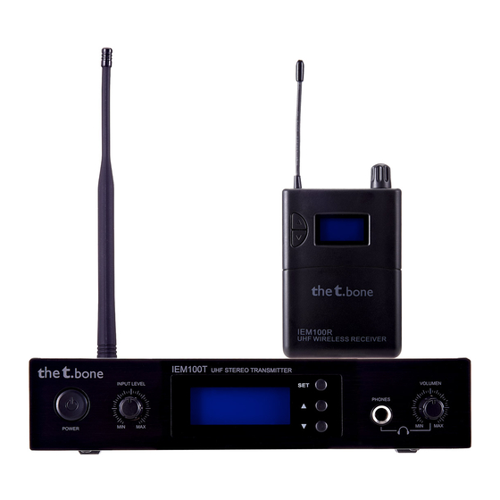
Components and functions Components and functions 5.1 Transmitter Front panel of the transmitter ö % & .bone IEM100T UHF STEREO TRANSMITTER INPUT LEVEL VOLUMEN PHONES POWER UHF wireless system... - Page 23 Components and functions 1 POWER Main switch to turn the device on or off. For turning on, keep this button pressed for one second. 2 INPUT LEVEL Control for adjusting the input sensitivity. 3 Display 4 SET Enter button for menu control. Buttons for increasing / decreasing the currently indicated value.
- Page 24 Components and functions Rear panel of the transmitter PUSH PUSH DC INPUT 12V-18V 300mA -12 dB 0 dB RoHS AF INPUT POWER LEFT INPUT RIGHT INPUT FREQ. ANTENNA 768~788MHz UHF wireless system...
- Page 25 Components and functions 8 DC INPUT Connect the cable of the supplied mains adapter to this socket. If using another power adapter make sure it provides the correct voltage, plug polarity and sufficient power. 9, 10 LEFT INPUT / RIGHT INPUT XLR/1/4"...
- Page 26 Components and functions Display of the transmitter A Limiter Indicates Limiter action as protection against volume peaks. B Stereo/Mono Indicates the selected operating mode (stereo or mono). C Level indicator for left and right channel. Indicates that the unit is locked to prevent unintentional operation. E Indicates the frequency that is assigned to the set combination of frequency group and channel ( Ä...
-
Page 27: Receiver
Components and functions 5.2 Receiver Front panel of the receiver 13 Flexible antenna. 14 ON/OFF/MAX Main switch and volume control. Turn this knob clockwise past the point of resist‐ ance to turn on the receiver. Turn it further to increase the volume. Turn this knob counter-clockwise to reduce the volume. - Page 28 Components and functions 19 ESC Function „Cancel/EXIT“ in the menu. Buttons for increasing / decreasing the currently indicated value. Top panel of the receiver 21 PHONES 1/8" mini phone socket (stereo) for the earplugs. PHONES 22 RF This LED lights up on incoming radio signal. UHF wireless system...
- Page 29 Components and functions Rear panel of the receiver 23 Indication of the frequency range in which the device operates. The specification here must match the specification printed on the back of the transmitter. 24 Clip to attach the transmitter to your belt or guitar strap. FREQ.
- Page 30 Components and functions Display of the receiver H GR Indicates the selected frequency group. I CH Indicates the selected channel. J LIM Indicates Limiter action as protection against volume peaks. K HF Indicates the activated high frequency boost function. L Battery level indicator. Replace the batteries when only one bar remains displayed. M Radio signal strength indicator (one to five bars).
- Page 31 Components and functions Indicates that the unit is locked to prevent unintentional operation. P Indicates the frequency that is assigned to the set combination of frequency group and channel ( Ä Chapter 8.3 ‘Frequency charts’ on page 43). IEM 100...
-
Page 32: Operating
Operating Operating 6.1 Setting up the transmitter Selecting frequency group and channel Press the [SET] button repeatedly until the ‘GROUP’ field (frequency group) flashes in the dis‐ play. Use the buttons to increase or decrease the indicated value by one. When the desired value is shown press the [SET] button to confirm the setting and proceed to the next menu item. - Page 33 Operating Transmitter and receiver must be set to the same combination of frequency group and channel. If you use multiple wireless systems from this device family, for best results you should assign all systems to the same frequency group, but give each system a different channel.
- Page 34 Operating Locking against changes Press the [SET] button repeatedly until ‘ON’ or ‘OFF’ and the symbol are flashing in the dis‐ play. Use the buttons to toggle between locked status (display = ‘ON’ ) and normal operation (display = ‘OFF’ ). In locked status, you can view the system settings, but you can't change them.
-
Page 35: Setting Up The Receiver
Operating 6.2 Setting up the receiver The [SET] and [ESC] buttons that you need to set up the receiver are located behind the battery compartment lid. IEM 100... - Page 36 Operating Selecting frequency group and channel Press the [SET] button repeatedly until the ‘GROUP’ field (frequency group) flashes in the dis‐ play. Use the buttons to increase or decrease the indicated value by one. When the desired value is shown press the [SET] button to confirm the setting and proceed to the next menu item.
- Page 37 Operating Turning on the treble boost Press the [SET] button repeatedly until ‘ON’ or ‘OFF’ and the ‘HF’ field are flashing in the dis‐ play. Use the button to turn the treble boost function on or off (display = ‘ON’ or ‘OFF’...
-
Page 38: Troubleshooting
Troubleshooting Troubleshooting In the following we list a few common problems that may occur during operation. We give you some suggestions for easy troubleshooting: UHF wireless system... - Page 39 Troubleshooting Symptom Remedy No sound 1. Check the power supply of the transmitter and receiver. 2. Make sure that both transmitter and receiver operate in the same frequency range and that the transmitting antenna is designed for this frequency range. The frequency range is stated on the devices.
- Page 40 3. Interference can also be caused by televisions, radios or mobile phones. The sound is distorted. Change the ‘INPUT LEVEL’ control setting on the transmitter. If the procedures recommended above do not succeed, please contact our Service Center. You can find the contact information at www.thomann.de. UHF wireless system...
-
Page 41: Technical Specifications
Technical specifications Technical specifications 8.1 Transmitter Input 2 × XLR / 1/4" phone combo socket (balanced) Headphones output 1/4" phone socket (stereo) Modulation type Frequency modulation (FM) Transmission level 10 dBm Input impedance 100 kΩ Maximum audio input level +12 dBV Gain range 40 dB NF frequency response... -
Page 42: Receiver
Technical specifications Operating voltage supply DC 12…18 V , 300 mA, via supplied power adapter Dimensions (W × D × H, without antenna) 212 mm × 160 mm × 44 mm Weight 960 g 8.2 Receiver Modulation type Frequency modulation (FM) Image rejection >... -
Page 43: Frequency Charts
Technical specifications 8.3 Frequency charts the t.bone IEM 100 770 MHz (Item no. 269815) Frequency group 1 Channel 1 Channel 2 Channel 3 Channel 4 Channel 5 Channel 6 Channel 7 Channel 8 768.000 MHz 768.625 MHz 768.975 MHz 769.350 MHz 770.175 MHz... - Page 44 Technical specifications the t.bone IEM 100 770 MHz (Item no. 269815) Frequency group 3 Channel 1 Channel 2 Channel 3 Channel 4 Channel 5 Channel 6 Channel 7 Channel 8 768.425 MHz 769.775 MHz 770.600 MHz 771.050 MHz 772.075 MHz 773.150 MHz...
- Page 45 Technical specifications the t.bone IEM 100 770 MHz (Item no. 269815) Frequency group 5 Channel 1 Channel 2 Channel 3 Channel 4 Channel 5 Channel 6 Channel 7 Channel 8 769.125 MHz 769.750 MHz 770.475 MHz 771.300 MHz 772.250 MHz 773.850 MHz...
- Page 46 Technical specifications the t.bone IEM 100 770 MHz (Item no. 269815) Frequency group 7 Channel 1 Channel 2 Channel 3 Channel 4 Channel 5 Channel 6 Channel 7 Channel 8 769.625 MHz 770.975 MHz 771.375 MHz 772.250 MHz 773.275 MHz 774.350 MHz...
- Page 47 Technical specifications the t.bone IEM 100 770 MHz (Item no. 269815) Frequency group 9 Channel 1 Channel 2 Channel 3 Channel 4 Channel 5 Channel 6 Channel 7 Channel 8 770.350 MHz 771.325 MHz 772.100 MHz 773.475 MHz 774.475 MHz 775.725 MHz...
- Page 48 Technical specifications the t.bone IEM 100 800 MHz (Item no. 137618) Frequency group 1 Channel 1 Channel 2 Channel 3 Channel 4 Channel 5 Channel 6 Channel 7 Channel 8 790.850 MHz 791.475 MHz 792.525 MHz 793.150 MHz 795.550 MHz 797.050 MHz...
- Page 49 Technical specifications the t.bone IEM 100 800 MHz (Item no. 137618) Frequency group 3 Channel 1 Channel 2 Channel 3 Channel 4 Channel 5 Channel 6 Channel 7 Channel 8 790.875 MHz 791.450 MHz 792.550 MHz 793.175 MHz 795.575 MHz 797.075 MHz...
- Page 50 Technical specifications the t.bone IEM 100 800 MHz (Item no. 137618) Frequency group 5 Channel 1 Channel 2 Channel 3 Channel 4 Channel 5 Channel 6 Channel 7 Channel 8 790.900 MHz 791.425 MHz 792.575 MHz 793.200 MHz 795.600 MHz 797.100 MHz...
- Page 51 Technical specifications the t.bone IEM 100 800 MHz (Item no. 137618) Frequency group 7 Channel 1 Channel 2 Channel 3 Channel 4 Channel 5 Channel 6 Channel 7 Channel 8 790.925 MHz 793.225 MHz 794.100 MHz 795.625 MHz 797.125 MHz 798.925 MHz...
- Page 52 Technical specifications the t.bone IEM 100 800 MHz (Item no. 137618) Frequency group 9 Channel 1 Channel 2 Channel 3 Channel 4 Channel 5 Channel 6 Channel 7 Channel 8 790.950 MHz 793.425 MHz 794.125 MHz 795.650 MHz 797.150 MHz 798.950 MHz...
- Page 53 Technical specifications the t.bone IEM 100 863 MHz (Item no. 137793) Channel 1 Channel 2 Channel 3 Channel 4 Channel 5 Channel 6 Channel 7 Channel 8 863.100 MHz 863.900 MHz 864.500 MHz 864.900 MHz 863.200 MHz 863.300 MHz 863.400 MHz 863.500 MHz...
-
Page 54: Protecting The Environment
Protecting the environment Protecting the environment Disposal of the packaging mate‐ rial For the transport and protective packaging, environmentally friendly materials have been chosen that can be supplied to normal recycling. Ensure that plastic bags, packaging, etc. are properly disposed of. Do not just dispose these materials with your normal household waste, but make sure that they are fed to a recovery. - Page 55 Protecting the environment Disposal of batteries Batteries must not be disposed of as domestic waste or thrown into fire. Dispose of the bat‐ teries according to national or local regulations regarding hazardous waste. To protect the environment, dispose of empty batteries at your retail store or at appropriate collection sites. IEM 100...
- Page 56 Notes UHF wireless system...
- Page 57 Notes IEM 100...
- Page 58 Notes UHF wireless system...
- Page 60 Musikhaus Thomann e.K. · Treppendorf 30 · 96138 Burgebrach · Germany · www.thomann.de...
Need help?
Do you have a question about the t.bone IEM 100 and is the answer not in the manual?
Questions and answers