Table of Contents
Advertisement
Quick Links
Advertisement
Table of Contents

Related Manuals for thomann t.bone IEM D2.4


Summary of Contents for thomann t.bone IEM D2.4
- Page 1 IEM D2.4 UHF Wireless System...
- Page 2 Thomann GmbH Hans-Thomann-Straße 1 96138 Burgebrach Germany Telephone: +49 (0) 9546 9223-0 Internet: www.thomann.de 26.04.2024, ID: 513822 (V2)
-
Page 3: Table Of Contents
Table of contents Table of contents General information..........................6 1.1 Symbols and signal words....................... 6 Safety instructions............................. 8 Features and scope of delivery......................11 Installation and starting up........................ 13 4.1 General Information........................13 4.2 Transmitter............................14 4.3 Receiver............................... 15 Connections and controls........................17 5.1 Transmitter............................ - Page 4 Table of contents Plug and connection assignment....................35 Troubleshooting............................38 Protecting the environment......................40 IEM D2.4 UHF Wireless System...
- Page 5 IEM D2.4 UHF Wireless System...
-
Page 6: General Information
Our products and documentation are subject to a process of continuous development. They are therefore subject to change. Please refer to the latest version of the documentation, which is ready for download under www.thomann.de. 1.1 Symbols and signal words In this section you will find an overview of the meaning of symbols and signal words that are used in this document. - Page 7 General information Signal word Meaning DANGER! This combination of symbol and signal word indicates an immediate dangerous situation that will result in death or serious injury if it is not avoided. WARNING! This combination of symbol and signal word indicates a pos‐ sible dangerous situation that can result in death or serious injury if it is not avoided.
-
Page 8: Safety Instructions
Safety instructions Safety instructions Intended use This device is intended to be used for the wireless transmission of audio signals to earplugs. Use the device only as described in this user manual. Any other use or use under other oper‐ ating conditions is considered to be improper and may result in personal injury or property damage. - Page 9 Safety instructions WARNING! Incorrect handling of lithium batteries can result in injury! In the event of a short circuit, overheating or mechanical damage, lithium batteries can cause severe injuries. Handle lithium bat‐ teries in a correct and professional manner. Store lithium batteries in a cool and dry place in their original packaging. Keep lithium batteries away from sources of heat.
- Page 10 Safety instructions NOTICE! Possible damage due to leaking batteries! Batteries can leak and cause permanent damage to the device. Take the batteries out of the device if it is not going to be used for an extended period of time. NOTICE! Possible damage to lithium-ion batteries through incorrect storage! Deep discharge can permanently damage lithium-ion batteries or cause them to lose some of their capacity.
-
Page 11: Features And Scope Of Delivery
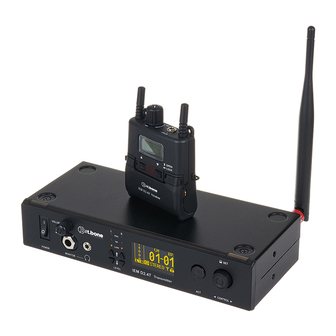
Features and scope of delivery Features and scope of delivery The UHF wireless system IEM D2.4 is an in-ear monitoring system especially suitable for profes‐ sional events, on rock stages and in concert halls, theatres and musicals. Your UHF wireless system IEM D2.4 consists of the following components: 9.5"... - Page 12 Features and scope of delivery 8 systems can be operated simultaneously. The system operates within a frequency range of 2400 MHz to 2483 MHz. Included accessories: Power supply, lithium-ion battery, rack mount, charging station and antenna converter Optional accessories: Earphones, lithium-ion replacement battery (item no. 453988) and mounting material for rack-mounting two transmitters (item no.
-
Page 13: Installation And Starting Up
For more information, please visit: http://www.thomann.de. Make sure that transmitter and receiver are both tuned to the same channel. -
Page 14: Transmitter
Installation and starting up 4.2 Transmitter Rack mounting The unit has been designed for rack mounting in a standard 19-inch rack; it occupies one rack unit. Connecting the power supply NOTICE! Damage to the external power supply due to high voltages! The device is powered by an external power supply. -
Page 15: Receiver
Installation and starting up Attaching the antenna Attach the included antenna to the back of the transmitter. To improve transmission quality and adapt to spatial conditions, it can be rotated and swivelled. Connecting audio and starting Connect the audio inputs of the transmitter with suitable line outputs of your mixer or your amplifier. - Page 16 Installation and starting up Turn on the transmitter and the receiver and test the transmission. Make sure that trans‐ mitter and receiver are tuned to the same channel. If necessary, adjust the volume on the transmitter and receiver as well as the levels on your mixer or amplifier. IEM D2.4 UHF Wireless System...
-
Page 17: Connections And Controls
Connections and controls Connections and controls 5.1 Transmitter Front panel ö & IEM D2.4T Transmitter IEM D2.4 UHF Wireless System... - Page 18 Connections and controls 1 [POWER] | Main switch 2 [VOLUME] | Volume control 3 [L] / [R] / [PEK] / [OK] / [LOW] | Left and right sound quality indicator LEDs 4 [ACT] | Synchronisation button 5 [CONTROL] | Rotary control for adjusting parameters. Turn the control to select an option, press the control to con‐ firm.
- Page 19 Connections and controls Rear panel PUSH PUSH ANTENNA IEM D2.4T Transmitter LOOP OUT 12-15V ö & IEM D2.4 UHF Wireless System...
- Page 20 Connections and controls 1 UHF antenna 2 [OUT] / [IN] | RJ11 sockets (no function) 3 [LOOP OUT] / [L] / [R] | 6.35-mm jack sockets (mono). The input signals are available at these outputs for forwarding to other wireless systems or other audio devices. 4 [LEFT /CH1.IN] / [RIGHT /CH2.IN] | XLR/6.35-mm jack combination sockets (left and right channels) for direct connec‐...
- Page 21 Connections and controls Display 1 Level meter for the left and the right audio input. ö 2 Channel display 3 ID indicator 4 Lock icon 5 Radio signal activated (antenna symbol) or deactivated (no antenna symbol) 6 Audio input stereo or mono 7 Icon for the audio source &...
-
Page 22: Receiver
Connections and controls 5.2 Receiver Front panel 1 Antenna ö ö 2 [OFF] / [VOL] | Main switch and volume control. Turn this control clockwise past the point of resistance to turn on the receiver. Turn it further to increase the volume. Turn this control anti-clockwise to reduce the volume. - Page 23 Connections and controls Display 1 Channel and ID display ö 2 Displays the selected channel and ID 3 Antenna signal display. Without the antenna icon, the bars indicate environmental interference. 4 Battery charge level indicator 5 Audio display Top: left channel Bottom: right channel.
-
Page 24: Operating
Operating Operating 6.1 Setting up the transmitter Press [CONTROL] to enter the main menu. Setting parameters Turn [CONTROL] to the left or right to select a menu item. Press [CONTROL] to confirm. Select ‘Exit&Safe’ and press [CONTROL] to save the settings and return to the main menu. Menu item Values Explanation... - Page 25 Operating Menu item Values Explanation ‘SetLock’ ‘YES’ / ‘NO’ Lock activated or deactivated. When the lock is activated, no changes can be made to the settings. ‘Net’ No function ‘Version?’ Display of the current firmware version ‘Exit&Safe’ Saving changes and back to the main menu Setting input level Press the buttons (6) to set the input level to 0.
- Page 26 Operating Headphone monitoring Use [VOLUME] to turn the volume down to minimum. Connect headphones to the connection (3) or (4). Use [VOLUME] to set an appropriate volume. ACT synchronisation Press the [ACT] synchronisation button to activate synchronisation. ð The display shows ‘ACT...’ . Align the transmitter and the sync window on the receiver within 30 cm of each other.
-
Page 27: Setting Up The Receiver
Operating 6.2 Setting up the receiver Adjusting the volume Turn the main switch / volume control (18) clockwise to switch on the device. ð The display is switched on and shows the current channel when the battery is suffi‐ ciently charged. Turn the main switch / volume control (18) clockwise to increase the volume or counter‐... - Page 28 Operating Menu item Values Explanation ‘CH-ID’ ‘1’ … ‘8’ Setting channel and ID Choose the same values as for the transmitter. ‘01’ … ‘64’ ‘AF MODE’ ‘STEREO’ Selecting the receiver mode ‘MIXED’ ‘MIXED’ : You can hear the two inputs in both ears and vary the ratio of the two inputs using the balance.
- Page 29 Operating Menu item Values Explanation ‘EARDRIVE’ ‘NORM’ Four selectable sound presets to improve the basic sound of connected earphones. ‘LIVE’ ‘PRO’ ‘EXTRA’ ‘SET LOCK’ ‘LOCK’ Lock activated or deactivated. When the lock is activated, no changes can be made to the settings. ‘UNLOCK’...
-
Page 30: Technical Specifications
Technical specifications Technical specifications 7.1 Receiver Number of systems that can be operated 8 systems in parallel Output connections Headphones 1 × 3.5-mm jack socket, stereo Impedance: 16 Ω Receive mode: True diversity Latency: < 3.7 ms Output level adjustment +12 dBu Frequency range 2.400 GHz …... - Page 31 Technical specifications Battery Battery type ICR-18500 lithium-ion battery (replaceable, item no. 453988) Voltage 3.7 V Capacity 1,400 mAh Operating time Dimensions (W × H × D) 63 mm × 96 mm × 25 mm Weight 98 g Ambient conditions Temperature range 0 °C…40 °C Relative humidity 20%…80% (non-condensing)
-
Page 32: Transmitter
Technical specifications 7.2 Transmitter Number of systems that can be oper‐ 8 systems ated in parallel Input connections Power supply Connection socket for the power adapter Audio 2 × XLR / 6.35-mm jack combo socket Output connections Headphones 1 × 6.35-mm jack socket, balanced 1 ×... - Page 33 Technical specifications NF frequency response 5 Hz…23 kHz Total harmonic distortion > 0.07% Signal-to-noise ratio > 115 dB (A) Power supply External power adapter, 100 - 240 V 50/60 Hz Operating voltage 12 V / 1 A, centre positive Dimensions (W × H × D) 209 mm ×...
-
Page 34: Battery Charging Station
Technical specifications 7.3 Battery charging station Battery Battery type ICR-18500 lithium-ion battery Voltage 3.7 V Capacity 1,400 mAh Power supply External power adapter, 100 - 240 V 50/60 Hz Operating voltage 12 V / 1 A, centre positive Current consumption 600 mA Dimensions (W ×... - Page 35 Plug and connection assignment Plug and connection assignment Introduction This chapter will help you select the right cables and plugs to connect your valuable equip‐ ment in such a way that a perfect sound experience is ensured. Please note these advices, because especially in ‘Sound & Light’ caution is indicated: Even if a plug fits into the socket, an incorrect connection may result in a destroyed power amp, a short circuit or ‘just’...
- Page 36 Plug and connection assignment 1/4" TS phone plug (mono, unbalanced) Signal Ground, shielding Three-pole 1/8" mini phone jack (stereo, unbalanced) Signal (left) Signal (right) Ground, shielding 1/4" TRS phone plug (stereo, unbalanced) Signal (left) Signal (right) Ground IEM D2.4 UHF Wireless System...
- Page 37 Plug and connection assignment XLR plug for signal input on the XLR / 6.35-mm jack combo sockets serve as signal input on the transmitter. The drawing and transmitter (balanced) table show the XLR pin assignment (balanced wiring) and the assignment of a suitable jack plug.
- Page 38 Troubleshooting Troubleshooting In the following we list a few common problems that may occur during operation. We give you some suggestions for easy troubleshooting: Symptom Remedy No sound 1. Check the power supply of the transmitter and receiver. 2. Are the transmitter and receiver set to the same channel? 3.
- Page 39 4. Interference can also be caused by televisions, radios or mobile phones. The sound is distorted 1. Change the volume control setting on the transmitter. If the procedures recommended above do not succeed, please contact our Service Center. You can find the contact information at www.thomann.de. IEM D2.4 UHF Wireless System...
- Page 40 Protecting the environment Protecting the environment Disposal of the packing material Environmentally friendly materials have been chosen for the packaging. These materials can be sent for normal recycling. Ensure that plastic bags, packaging, etc. are disposed of in the proper manner. Do not dispose of these materials with your normal household waste, but make sure that they are collected for recycling.
- Page 41 When disposing of the device, comply with the rules and regulations that apply in your country. You can also return your old device to Thomann GmbH at no charge. Check the current conditions on www.thomann.de.
- Page 42 Notes IEM D2.4 UHF Wireless System...
- Page 44 Musikhaus Thomann · Hans-Thomann-Straße 1 · 96138 Burgebrach · Germany · www.thomann.de...
Need help?
Do you have a question about the t.bone IEM D2.4 and is the answer not in the manual?
Questions and answers