Technibel PHRT 7 Installation Instruction
Hide thumbs
Also See for PHRT 7:
- Technical instructions (12 pages) ,
- Installation instructions manual (24 pages)
Table of Contents
Advertisement
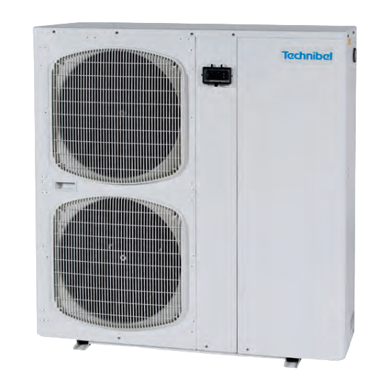
PHRT 7
PHRT 9
Pompe à chaleur avec équipement hydraulique - Fluide réfrigérant R 410 A
Heat pump with hydraulic equipment - R 410 A refrigerant
Refrigeratore d'acqua in versione pompa di calore con sezione idronica incorporata
Bomba de calor con equipamiento hidráulico - Fluido refrigerante R 410 A
Wärmepumpe mit Hydraulikmodul Kältemittel R 410 A
Bomba de calor com equipamento hidráulico - Fluído refrigerante R 410 A
Avril 2008
(Etiquette signalétique)
PHRT 7 / 16
PHRT 12
PHRT 16
Fluido refrigerante R 410 A
NOTICE
D'INSTALLATION
INSTALLATION
INSTRUCTION
MANUALE
D'INSTALLAZIONE
MANUAL
DE INSTALACIÓN
AUFSTELLUNGS-
HANDBUCH
INSTRUÇÕES
DE INSTALAÇÃO
10 11 501 - F.GB.I.E.D.P - 01
F
GB
I
E
D
P
Advertisement
Table of Contents

Related Manuals for Technibel PHRT 7


Summary of Contents for Technibel PHRT 7
- Page 1 DE INSTALACIÓN AUFSTELLUNGS- (Etiquette signalétique) HANDBUCH INSTRUÇÕES DE INSTALAÇÃO PHRT 7 / 16 PHRT 12 PHRT 16 PHRT 7 PHRT 9 Pompe à chaleur avec équipement hydraulique - Fluide réfrigérant R 410 A Heat pump with hydraulic equipment - R 410 A refrigerant Refrigeratore d’acqua in versione pompa di calore con sezione idronica incorporata...
-
Page 2: Table Of Contents
MARKING This product marked conforms to the essential requirements of the Directives: - Low voltage no. 2006/95/EC. - Electromagnetic Compatibility no. 89/336 EEC, modified 92/31 and 93/68 EEC. SUMMARY 1 - Generalities ......... . 2 2 - Presentation . -
Page 3: Presentation
6 - Electrical box. 15 - Air vent. - Plastic grille. 7 - Microprocessor control unit display 16 - Hole for connecting cables. keyboard. 8 - Circulating pump. 9 - Expansion tank. PHRT 7 PHRT 9 PHRT 12 PHRT 16... -
Page 4: Dimensions And Weight
2.2 - DIMENSIONS AND WEIGHT Weight (kg) PHRT 7 PHRT 9 Water inlet connection 3/4" (male) with air vent valve Water outlet connection 3/4" (male) Water circuit fill/drain - 1/2" male Holes for electric cables 1190 Weight (kg) PHRT 12 PHRT 16 Water inlet connection 1"... -
Page 5: Installation
(see below), A (m) - use the anti-vibration mountings supplied, making sure that they are not PHRT 7/9 0.15 compressed too much when the fastening screws are tightened, PHRT 12/16 0.25... -
Page 6: Hydraulic Connection
The unit is designed to be connected to a power supply having a TT neutral regime (neutral to ground) or TN.S regime (to neutral) as per NF C 15-100. POWER SUPPLY CABLE • Section 230V/1/50Hz for PHRT 7, 9 and 12. : 3 G 4 mm • Section 400V/3N/50Hz : 5 G 2.5 mm for PHRT 9, 12 and 16. -
Page 7: Operation Of "Ech" Electronic Control
4.3.4 - REMOTE CONTROL • See paragraph "accessories". 4.3.5 - MISCELLANEOUS • Alarm transfer: Potential-free changeover contact (2A - 250 VAC max.) available on the unit's terminal strip (terminals 5 (common), 6 and 7 of the printed circuit) for remote signaling. See schematic. - In case of alarm : - contact open between terminals 5 and 6, - contact closed between terminals 5 and 7. -
Page 8: Operating Modes
5.3.2 - CTN TYPE TEMPERATURE PROBE Temperature (°C) Ohmic value (Ohm) • 10 kΩ at 25° C. 67 740 42 450 27 280 17 960 12 090 10 000 8 313 5 820 4 161 3 021 2 229 5.4 - OPERATING MODES •... - Page 9 5.6 - PARAMETERS - DISPLAYING AND ADJUSTING 5.6.1 - GENERAL • Parameter access is structured within a multi-level menu, see the diagram below. Simultaneously pressing the "ON/OFF" (1) and "Mode" (2) buttons for a brief moment (less than 2 seconds) gives access to the next level. Simultaneously pressing for a long moment (longer than 2 seconds) turns you to the previous level.
- Page 10 5.6.3 - SETPOINT ADJUSTMENT • Simultaneously press buttons (1) and (2) for at least 2 seconds, "SET" is displayed. • Press the 2 buttons again, "Coo" is displayed. Using button (1) or (2), display either "HEA" or "Coo" corresponding to the heating setpoint ("HEA") or cooling setpoint ("Coo").
- Page 11 SUMMARY TABLE OF ALARMS Compressor Circulating pump Alarm Code Inhibition delay Fan stop Remarks shut-down stop Fault on probe 1 Fault on probe 2 Fault on probe 3 Forced circulating Fault on probe 4 pump operation H.P. B.P. (low pressure) 30'' at start-up From probe Anti-freeze (water...
- Page 12 • Condensate tank heating cord control: (Accessory, see installation in paragraph 6.2). - actuated if the outside temperature (probe SD4) drops below 0°C (regardless the unit's operating mode). The "heating element" indicator light (8) illuminates. • Operating mode selection: - the controller is factory configured to control the unit by 2 outside contacts: •...
-
Page 13: Accessories
6.1 - WATER CONNECTION HOSES • Length 1 m, insulated, female: - Ø 3/4” code 70600054 for PHRT 7 and 9, - Ø 1” code 70600055 for PHRT 12 and 16. 6.2 - CONDENSATE TANK HEATING CORD KIT (if not factory installed) •... -
Page 14: Remote Control
6.3 - REMOTE CONTROL • Code 70250055. • The functions and display are exactly the same as those on controller. • The only difference concerns the buttons which are separated by the “ON/OFF” and “Mode” buttons. • Reminder: the parameters are accessed by simultaneously pressing the “ON/OFF”... -
Page 15: Starting
7 - STARTING IMPORTANT NOTE Before carrying out any work on the installation, make sure that it is switched off and that access to it is prevented. Any work must be carried out by personnel qualified and authorised to work on this type of machine. 7.1 - CHECK •... -
Page 16: Maintenance Instruction
8 - MAINTENANCE INSTRUCTIONS IMPORTANT NOTE • Before carrying out any work on the installation, make sure that it is switched off and that access to it is prevented. • Also check the discharge of the compressor capacitor for the single-phase voltages. •... -
Page 17: Circulator Curves
10 - CIRCULATOR CURVES PHRT 7 CIRCULATOR SXM 32 - 55 CIRCULATOR UPS 25 - 125 PHRT 12 PHRT 9 Speed 3 Speed 3 Speed 2 Speed 2 Speed 1 Speed 1 Water flowrate (m Water flowrate (m 1.87 2.16 1.19... -
Page 18: Pressure Curves
11 - PRESSURE CURVES 11.1 - HEATING MODE LOW PRESSURE HIGH PRESSURE PHRT 7 55° C Water outlet temperature Water outlet temperature 55° C 50° C 50° C 45° C 45° C 40° C 40° C -10 -8 -6 -4 -2... -
Page 19: Cooling Mode
11.2 - COOLING MODE LOW PRESSURE HIGH PRESSURE PHRT 7 35° C Outside temperature 43° C Outside temperature 43° C 25° C 35° C 25° C 9 10 11 12 13 14 15 16 17 18 19 20 9 10 11 12 13 14 15 16 17 18 19 20 Water outlet temperature (°C) -
Page 20: Wiring Diagrams
Filter SD4 Outside air probe High pressure switch White M11 Fan Low pressure switch Compressor EV1 Electrovalve ELECTRICAL DIAGRAM - PHRT 7/9 - 230/1/50 10 05 824 - 01 Controller Filter Starter Interface panel KM3 A1 Alarm Compressor Circulating... - Page 21 ELECTRICAL DIAGRAM - PHRT 12 - 230/1/50 10 05 825 - 01 Controller Filter K A4 Starter Interface panel KM3 A1 Alarm Fan 1 Fan 2 Compressor Circulator ELECTRICAL DIAGRAM - PHRT 12/16 - 400/3N/50 10 05 816 - 00 Controller Filter Interface panel...
- Page 24 Par souci d'amélioration constante, nos produits peuvent être modifiés sans préavis. Due to our policy of continuous development, our products are liable to modification without notice. Per garantire un costante miglioramento dei nostri prodotti, ci riserviamo di modificarli senza preaviso. En el interés de mejoras constantes, nuestros productos pueden modificarse sin aviso prévio.
Need help?
Do you have a question about the PHRT 7 and is the answer not in the manual?
Questions and answers