Table of Contents
Advertisement
Quick Links
Pompe à chaleur haute température avec équipement hydraulique
High temperature heat pump with hydraulic equipment
Refrigeratore d'acqua in versione pompa di calore alta temperatura con sezione idronica
incorporata (unicamente riscaldamento) - Fluido refrigerante R 407 C
Bomba de calor de alta temperatura con equipamiento hidráulico
Hochtemperatur-Wärmepumpe mit Hydraulikmodul
Bomba de calor alta temperatura com equipamento hidráulico
(somente aquecimento) - Fluído refrigerante R 407 C
Novembre 2008
(Etiquette signalétique)
PHTJ 14 / 19
(chauffage seulement) - Fluide réfrigérant R 407 C
(heating only) - R 407 C refrigerant
(sólo calefacción) - Fluido refrigerante R 407 C
(Nur Heizen) - Kältemittel R 407 C
NOTICE
D'INSTALLATION
INSTALLATION
INSTRUCTION
MANUALE
D'INSTALLAZIONE
MANUAL
DE INSTALACIÓN
AUFSTELLUNGS-
HANDBUCH
INSTRUÇÕES
DE INSTALAÇÃO
10 11 520 - F.GB.I.E.D.P - 02
F
GB
I
E
D
P
Advertisement
Table of Contents

Related Manuals for Technibel PHTJ 14/19


Summary of Contents for Technibel PHTJ 14/19
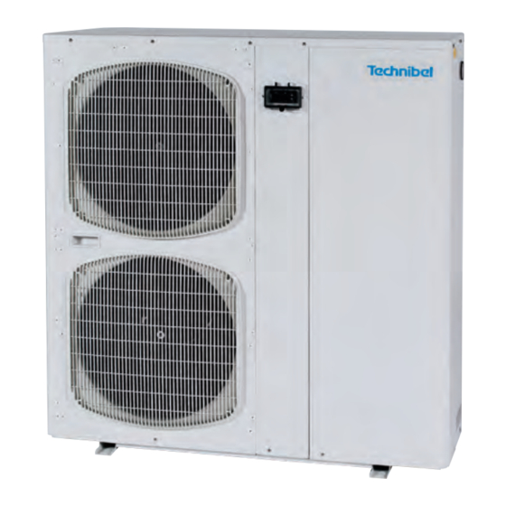
- Page 1 NOTICE D’INSTALLATION INSTALLATION INSTRUCTION MANUALE D’INSTALLAZIONE MANUAL DE INSTALACIÓN AUFSTELLUNGS- (Etiquette signalétique) HANDBUCH INSTRUÇÕES DE INSTALAÇÃO PHTJ 14 / 19 Pompe à chaleur haute température avec équipement hydraulique (chauffage seulement) - Fluide réfrigérant R 407 C High temperature heat pump with hydraulic equipment (heating only) - R 407 C refrigerant Refrigeratore d’acqua in versione pompa di calore alta temperatura con sezione idronica incorporata (unicamente riscaldamento) - Fluido refrigerante R 407 C...
-
Page 2: Table Of Contents
MARKING This product marked conforms to the essential requirements of the Directives: - Low voltage no. 2006/95/EC. - Electromagnetic Compatibility no. 89/336 EEC, modified 92/31 and 93/68 EEC. SUMMARY 1 - Generalities ......... . 2 2 - Presentation . -
Page 3: Presentation
1.3 - VOLTAGE • Before carrying out any operation, check that the voltage indicated on the unit corresponds to the mains voltage. • Before initiating maintenance or servicing on the installation, check that its power supply is disconnected and locked out. 1.4 - USE OF EQUIPMENT •... -
Page 4: Installation
- due to disturbance which may be caused by the noise, the blown air must A (m) not be directed towards surrounding windows, PHTJ 14/19 0.25 - vibrations and noise must not be transmitted to a nearby building, * This dimension does not account for the... -
Page 5: Hydraulic Connection
4.2 - HYDRAULIC CONNECTION • Connect the water pipes to the corresponding connections. See Ø and position on page 3. • Install the hydraulic filter (supplied) on the water intake. Connect it using 2 isolation valves (not supplied) for cleaning purposes. -
Page 6: Operation Of "Ech" Electronic Control
4.3.4 - REMOTE CONTROL • See paragraph "accessories". 4.3.5 - MISCELLANEOUS • Alarm transfer: Potential-free changeover contact (2A - 250 VAC max.) available on the unit's terminal strip (terminals 5 (common), 6 and 7 of the printed circuit) for remote signaling. See schematic. - In case of alarm: - contact open between terminals 5 and 6, - contact closed between terminals 5 and 7. -
Page 7: Operating Modes
5.3.2 - CTN TYPE TEMPERATURE PROBE Temperature (°C) Ohmic value (Ohm) • 10 kΩ at 25° C. 67 740 42 450 27 280 17 960 12 090 10 000 8 313 5 820 4 161 3 021 2 229 5.4 - OPERATING MODES •... - Page 8 5.6 - PARAMETERS - DISPLAYING AND ADJUSTING 5.6.1 - GENERAL • Parameter access is structured within a multi-level menu, see the diagram below. Simultaneously pressing the "ON/OFF" (1) and "Mode" (2) buttons for a brief moment (less than 2 seconds) gives access to the next level. Simultaneously pressing for a long moment (longer than 2 seconds) turns you to the previous level.
- Page 9 5.6.3 - SET POINT ADJUSTMENT • Simultaneously press buttons (1) and (2) for at least 2 seconds, "SET" is displayed. • Press the 2 buttons again, "HEA" is displayed. • Simultaneously press the 2 buttons again for 2 seconds. The setpoint value appears. If needed, modify the value with the buttons.
- Page 10 SUMMARY TABLE OF ALARMS Compressor Circulating pump Alarm Code Inhibition delay Fan stop Remarks shut-down stop Fault on probe 1 Fault on probe 2 Fault on probe 3 Forced circulating Fault on probe 4 pump operation H.P. (high pressure) B.P. (low pressure) or maximum 30'' at start-up discharge...
-
Page 11: Accessories
• Condensate tank heating cord control: - Actuated if the outside temperature (probe SD4) drops below 0°C (regardless the unit's operating mode). The "heating element" indicator light (8) illuminates. • Operating mode selection: - The regulator is configured in the factory for On/Stand-by control using an external contact. - In stand-by mode, the circulating pump continues to function. -
Page 12: Remote Control
• Place the heating element in the bottom of the tank, as close as possible to the fin tube exchanger. Heating cord location • Position the isolated end on the left side and along the exchanger to the back of the separating panel. Form a loop and return along the separating panel. -
Page 13: Starting
- Resistivity: 1 to 10 kΩ - Granulometry: < 0.4 mm - Fibre: no fibres Any disorder which may occur on our machines due to the poor quality of the fluid in the installation will not be covered by the TECHNIBEL warranty. -
Page 14: Maintenance Instruction
7.3 - STARTING-UP THE UNIT • Power up the unit. • Turn the water on. • Start the appliance (see paragraph 5). CAUTION: On three-phase units, make sure that the phase rotation order is correct. If the rotation order is not respected, the compressor will turn backwards (and make an abnormal noise). -
Page 15: Troubleshooting
8.2 - GENERATOR SHUT-DOWN DURING WINTER • 2 possibilities: 1) Drain the unit and disconnect the power supply. 2) Unit full of water and power on: as the unit is equipped with an antifreeze device which actuates the water circulating pump when the temperature drops below zero, it is imperative to ensure that the water can circulate within the unit. -
Page 16: Pressure Tables
11 - PRESSURE TABLES Low pressure High pressure PHTJ 14 Water outlet temperature Water outlet temperature 45° C 55° C 65° C 45° C 55° C 65° C 1.31 1.34 19.04 23.30 1.40 1.43 19.04 23.30 1.49 1.52 19.03 23.30 1.57 1.60 19.03... - Page 17 Low pressure High pressure PHTJ 19 Water outlet temperature Water outlet temperature 45° C 55° C 60° C 45° C 55° C 60° C 1.31 1.34 18.74 22.72 1.40 1.43 18.74 22.72 1.49 1.52 18.73 22.72 1.52 1.59 18.73 22.72 1.56 1.63 18.73...
-
Page 18: Wiring Diagrams
12 - WIRING DIAGRAMS Symbols of the components Colours of the wires Interface panel EV1 Electrovalve (reversal) Compressor Blue EV2 Electrovalve (injection Compressor starter Circulating pump Grey circuit) Fan speed control Anti-freeze resistor Brown Safety thermostat (accessory) Controller Purple Water differential pressure SD1 Water inlet probe M1 capacitor Pink... - Page 19 ELECTRICAL DIAGRAM - PHTJ 19 - 400/3N/50 10 05 841 - 02 Filter Controller Interface panel Alarm Fan 1 Fan 2 Compressor Circulator...
- Page 22 Par souci d'amélioration constante, nos produits peuvent être modifiés sans préavis. Due to our policy of continuous development, our products are liable to modification without notice. Per garantire un costante miglioramento dei nostri prodotti, ci riserviamo di modificarli senza preaviso. En el interés de mejoras constantes, nuestros productos pueden modificarse sin aviso prévio.
Need help?
Do you have a question about the PHTJ 14/19 and is the answer not in the manual?
Questions and answers
pdc phtj14/19
The PDC (presumably referring to power or electrical specifications) for the Technibel PHTJ 14/19 is as follows:
- PHTJ 14:
- Power supply: 230 V, single-phase, 50 Hz
- Nominal current: 24.8 A
- Maximum current: 32 A
- Starting current: 45 A
- Protection rating: 40 A
- Power cable cross-section: 3 G 6 mm²
- PHTJ 19:
- Power supply: 400 V, three-phase + neutral, 50 Hz
- Nominal current: 14.9 A
- Maximum current: 17.8 A
- Starting current: 101 A
- Protection rating: 20 A
- Power cable cross-section: 5 G 4 mm²
This answer is automatically generated