Table of Contents
Advertisement
Quick Links
P O B o x 7 0 , B a t t l e b o r o , N C 2 7 8 0 9
T e l : 2 5 2 - 9 8 4 - 0 7 0 0
F a x : 2 5 2 - 9 8 4 - 0 7 0 1
w w w . l s t r a c t o r . c o m
w w w . l s t r a c t o r u s a . c o m
P/NO
52105107
20110501
DATE
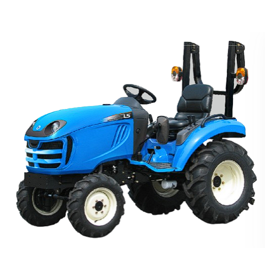
LS TRACTOR
OPERATOR'S MANUAL
J2020H
J2030H
I N N O V A T I V E
T E C H N O L O G Y
P A R T N E R
Advertisement
Table of Contents


Need help?
Do you have a question about the J2020H and is the answer not in the manual?
Questions and answers