Page 1
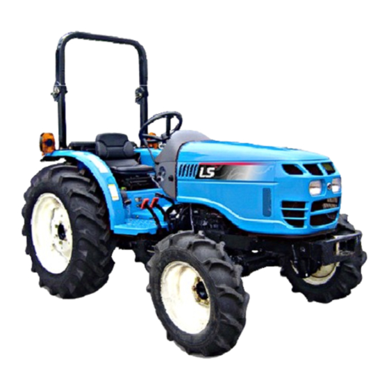
LS TRACTOR OPERATOR'S MANUAL G3033 G3033H G3038 G3038H P O B o x 7 0 , B a t t l e b o r o , N C 2 7 8 0 9 T e l : 2 5 2 - 9 8 4 - 0 7 0 0 F a x : 2 5 2 - 9 8 4 - 0 7 0 1 w w w .
Page 6
1. General Notices for Safety 1-1. Before using the tractor ※ ※ ※ ※ Read this Operator’s manual carefully, before using the tractor, to understand fully. ◆ ◆ ◆ ◆ General information for right use Your tractor is designed and manufactured to be used for agriculture. Do not use the product for improper purpose out of the intention of manufacturer, and follow the safety instructions provided by the Operator’s manual.
Page 7
◆ ◆ ◆ ◆ Product Identification Your tractor has a exclusive chassis number and engine number marked with product serial number tag to identify the product. (See Fig.1-1) In case of requesting service or parts from your dealer Dealer will need chassis serial number, engine Chassis No.
Page 8
1-2. Safety Precautions - read this for safety before using. (1) Notices before using For Safety Instruction : Before using the tractor, read the Operator‘s Manual carefully and Refer to Operator’s understand the instructions fully for the safety Manual. prevention and right usage of the tractor and then use the tractor safely according to the instructions.
Page 9
Tire air pressure, Wheel bolts, Toe-in, Electrical wirings, other items related to safety. Genuine Parts : When replacing parts, you must use Genuine Parts for LS tractor. Contact your authorized dealer. If not, it may cause a reduction of product life, failure and serious injury.
Page 10
Safety Structure : For the safety of the driver, various protection structures are attached on the tractor. If these structures are changed or detached by user arbitrarily, it may cause serious accident. Such behaviors are prohibited strictly and void the warranty. ▶...
Page 11
(3) Notices while operating/using the tractor Ventilation Warning I t is very dangerous to work in ▶ a closed area. The poisonous exhaust gas may cause serious injury to the human body. If you should work in this area, make sure to ventilate well and put on the protective mask.
Page 12
Obey the traffic rules while driving on public roads. Do not exceed the local legal speed limit. Use a sign beacon or slow moving vehicle (SMV) to indicate that the vehicle is slow moving. If you can not drive the tractor due to a failure, move the tractor to a safe place and install troubled vehicle (safety tripod).
Page 13
(4) Notices when connecting Implement Attach or detach the implement on wide and level ground. Do not stand between tractor and implement. Use hitch or drawbar for towing. Do not tow by connecting with any other structures. When connecting heavy implements, apply the parking brake and use the wheel chock.
Page 14
(6) Notices when transporting the tractor When transporting the tractor by truck, trailer, etc, use suitable equipment or facilities to load or unload the tractor. Fix the tractor tightly to the vehicle with heavy- duty straps or chains. When fixing the rear of the tractor, use the hitch or hitch support.
Page 15
(8) Notices when checking tractor after work The check and maintenance must be performed after stopping the engine and cooling down the engine sufficiently. DO NOT pour water into the radiator or engine when the engine is hot. The engine or radiator may crack.
Page 16
(9) Notices when handling Diesel Fuel Do not mix gasoline, alcohol or blended fuels to diesel fuel. These mixtures are explosive in fuel tank. Never remove the fuel cap or refuel with the engine running or hot. Do not smoke while refueling the tractor or when standing near fuel. Keep any type of flame away. Maintain control of the fuel filler nozzle when filling the fuel tank.
Page 17
1-3. Long-term storage (1) Preparation for storage Wash the tractor cleanly and follow the procedure ※ as below. Apply grease or lubricant oil or spray paint to the non-painted metal to avoid corrosion. Keep the tractor in a covered, dry and well-ventilated place. Temperature : 10 ~ 35 ~ 95...
Page 18
(2) Check & Maintenance during storage Apply grease or lubricant oil to non-painted metal to avoid corrosion. Check the leakage of fuel, oil and coolant. If necessary, repair the damaged part. The battery should be charged about once a month not to be discharged entirely. Check the tire air pressure and maintain the proper pressure.
Page 19
1-4. Notices for Use & Disposal related to Environment preservation Soil, Air and Water are essential elements for human life. To contribute to environment preservation of the Earth, we are trying to minimize the environment pollution necessitated by general business activity such as product design, manufacturing, distribution, etc. Several substances and products derived from chemical and petrochemical products are major portion of environment pollution and must be disposed of according to environment laws or related regulations, and common sense.
Page 20
1-5. Symbols The followings show the symbols and its meaning used for the tractor. Refer to User’s Gear Neutral Low speed Manual. Caution! Forward/Rearward High speed Engine speed Battery charging Forward control (throttle) Engine speed Engine speed Fuel level Fuel level Backward Backward control (throttle)
Page 21
1-6. Safety Decals (1) Handling and Maintenance of Safety Decals For right use and personal safety of the operator, the safety decals (labels) are attached to the parts related with safety operation. Before operating or maintenance of the parts, check the position and read the instructions carefully. The instructions described on the safety decals are very important for the safety of ▶...
Page 22
1. Position : Fuel Cap 2. Position : Starting motor 3. Position : PTO Cover 4. Position : Cooling fan 5. Position : Fender 6. Position : Fender 8. Position : Air cleaner 9. Position : Fender 7. Position : Radiator 10.
Page 23
2. The Name of Each Part (1) Roll-bar type Safety frame (Roll bar) Fender Fuel tank Driver’s seat Steering wheel Instrument panel Hood (Bonnet) Tire Sub step Headlight Bumper Front weight 2 2 2 2 - 1...
Page 24
3. Instruments and Controls 3-1. Instrument panel and Switches (1) The name of each part Turn signal Engine coolant Tachometer Fuel level gauge Turn signal indicator (LH) temperature gauge indicator (RH) Engine oil PTO operation pressure indicator indicator Fuel filter One side warning brake...
Page 25
(4) Tachometer and Hour meter Tachometer The tachometer shows the engine revolutions per minute. The operating hour 00005.3 means the tractor has been operated for 5.3hr (5 hours and 18 minutes). Hour meter (5) Engine coolant temperature Engine coolant temperature gauge gauge This gauge indicates the temperature of coolant This gauge indicates the temperature of coolant...
Page 26
(7) Turn signal light switch This switch is used when turning to the left or right. If turning the switch to clockwise, the right turn signal light and the indicator are blinking. - If turning the switch to counter-clockwise, the left turn signal light and the indicator are blinking.
Page 27
(11) Light switch ① EU version Light switch OFF - Instrument panel and all lights are OFF. - Instrument panel and sidelights are ON. - Instrument panel, sidelights, and High beam headlights (low beam) are ON. indicator - Instrument panel, sidelights, headlights (high beam) are ON.
Page 28
(13) Hazard warning light switch (optional) ① EU version This is used to warn other drivers to pay attention to emergency status. If you press the triangle switch, all turn signal lights and indicators shall be blinking. Hazard warning light switch ▶...
Page 29
(15) PTO operation indicator When the key switch is ON and PTO switch is operation ON, this indicator will be ON. indicator ON : PUSH AND TURN OFF : PUSH PTO switch (16) PTO switch (Independent PTO) The engine starts only when PTO switch is placed in OFF position for safety. The engine starts only when PTO switch is placed in OFF position for safety.
Page 30
(18) Parking brake indicator One side brake This indicator will be ON when applying the indicator parking brake or pressing brake pedal. (See page 3-11) Parking brake indicator (19) One side brake indicator (if fitted) Not used 3 3 3 3 - 7...
Page 31
3-2. Operating Levers and Pedals Important to owner, read carefully. Mechanical type Clutch pedal Brake pedal Shuttle lever Throttle pedal Throttle lever Differential lock pedal Range gear shift lever Main gear shift lever 4WD lever Brake pedal Reverse pedal Forward pedal Differential lock pedal Throttle lever...
Page 32
(1) Shuttle lever (Mechanical type) Forward It is used to select Forward / Reverse. If you push the lever forward, it runs forward and if you pull the lever back, it runs backward. Shuttle lever Backward Before moving tractor backward, lower the engine rpm and check behind you.
Page 33
(4) Clutch pedal (Mechanical type) This is used to engage or disengage the main transmission clutch for starting engine and shifting transmission gear. Depress the clutch pedal quickly and fully, and release it slowly. Clutch pedal D O NOT ride your foot on the clutch pedal while driving the tractor. D O NOT ride your foot on the clutch pedal while driving the tractor.
Page 34
(6) Parking brake lever Parking brake lever Connect brake pedals each other with brake connection plate. Push down the parking brake lever while pressing the brake pedals and check that serrated part is engaged to left brake pedal. Release the brake pedals slowly to check slippage of the tractor.
Page 35
(8) Range gear shift lever Mechanical Range gear shift lever Three speed ranges are available. Forward Range gear shift lever must be operated after the tractor has stopped completely. L L L L M M M M H H H H Range gear shift lever Forward Forward...
Page 36
(10) Differential lock pedal Mechanical If the tractor cannot go forward as one side rear wheels are slipping, press the differential lock pedal down. Differential lock pedal Differential lock is effective for working on slippery ground, and working with a plough If engaged, both rear wheels will rotate at equal speed.
Page 37
(12) HST neutral switch (HST type) It is located under the HST forward/reverse pedal and the switch shall be pressed if the pedal is placed on the NEUTRAL position as the pedal is not pressed. The engine does not start until the switch is pressed.
Page 38
(14) Driver’s seat (HST type) At the lower end of the seat, there is a switch to detect that operator is sitting in driver’s seat. Seat switch If the operator gets up from the seat while engine is running, the engine will stop automatically for safety in case of ;...
Page 39
3-3. Hydraulic system (1) Steering system As the steering system of your tractor has a hydraulic pump, valve and etc., it provides you more convenience to operate the steering wheel. Notices when using the steering system. 1. If there is too much of a load in front loader bucket, it could be difficult to operate the steering wheel. In this case, reduce the size of the load.
Page 40
① ① ① ① Position control This mode sets the position of implements freely by position control lever operation. Generally, Position control lever this mode is used for tiller, fertilizer distributor, mower, rake etc. In this case, operate the lever as follows.
Page 41
(3) Remote control lever and Quick coupler (if fitted) ※ This is used to operate the implement (i.e. Dump trailer, Hydraulic conversion plough, etc) attached to the tractor by the hydraulic pressure. If you pull the remote control lever backward, the hydraulic pressure works to the upper coupler, and the lower coupler is connected to the drain.
Page 42
(4) Hydraulic System Diagram Mechanical type 1. Hydraulic oil filter 6. Hydraulic lift pump 11. Hydraulic lift cylinder 2. Steering pump 7. Front outlet valve 12. Safety valve 3. Steering unit 3. Steering unit 8. Remote control valve 8. Remote control valve 13.
Page 43
1. Hydraulic filter 7. HST unit 12. Hydraulic lift control valve 2. Steering pump 8. Hydraulic lift pump 13. Down speed control valve 3. Steering unit 9. Front outlet valve 14. Safety valve 4. Steering cylinder 10. Independent PTO valve 15.
Page 44
3-4. Safety Device (1) Seat belt Always wear the seat belt before operating the tractor and adjust the belt to fit the operator. 1. Insert the seat belt end into the buckle until a click indicates it is properly engaged. 2.
Page 45
(3) Foldable Safety frame (Roll-bar type) (optional) How to fold the Safety frame. 1. Loosen the safety frame bolts and nuts (both sides) ② ④ loosely. (Do not unfasten it completely) 2. Remove the pins on the both side and fold the safety frame ③...
Page 46
4. Operation and Work 4-1. Engine start and stop ▶ C heck each part before starting engine. C heck if there is some other ▶ Caution people around before starting. P lace all the levers and switches in ▶ NEUTRAL or OFF position. (1) Engine start Mechanical type Mechanical type...
Page 47
C heck each part before starting ▶ engine. C heck if there is some other ▶ Caution people around before starting. P lace all the levers and switches in ▶ NEUTRAL or OFF position. HST type HST type HST type HST type 1.
Page 48
O nly start engine outdoors or in a well ventilated place, as the engine exhaust ▶ Warning fumes may cause sickness or death. . T o avoid an explosion, never use starting fluid to start engine. ▶ S tart the engine ONLY from the driver’s seat with placing all the transmission gear ▶...
Page 49
4-2. How to drive and how to stop (1) How to drive Mechanical type 1. Pull the position control lever Position control lever back to lift the implement up after starting engine. 2. Set the engine speed at 1500 rpm. rpm.
Page 50
HST type 1. Pull the position control lever Position control lever back to lift the implement up after starting engine. 2. Set the engine speed more than 1500 rev/min. Down speed control knob 3. Place the range gear shift lever in desired position.
Page 51
(2) Changing speed Mechanical type Depress the clutch pedal fully and operate all the shift lever correctly. For more information, refer to Operating Levers and Pedals in the Section 3-2. (See page 3-8) Clutch pedal HST type HST type Just pressing the HST forward / reverse pedal Throttle lever respectively makes it possible to travel forward and in reverse.
Page 52
(3) Emergency Stop Mechanical type 1. Press the clutch pedal and brake Throttle lever Clutch pedal at the same time to stop the tractor. pedal Turn OFF the key switch. 2. DO NOT release clutch pedal until all moving parts have stopped. Apply the parking brake.
Page 53
(4) Stopping tractor Mechanical type Throttle lever PTO switch Key switch Clutch pedal 1. Press the clutch and brake pedal. Place the shuttle lever, main gear shift lever in NEUTRAL and PTO switch to OFF and release the clutch pedal. 2.
Page 54
(5) Driving tractor on the road When facing downhill, DO NOT place the gear lever in NEUTRAL position. When driving the tractor on a unpaved road by attaching an implement to 3-point linkage, place the gear lever to low speed and DO NOT lift the implement up to the highest position. When the tractor bumps an obstacle, it may cause the jolting of the implement and the failure of hydraulic system.
Page 55
(6) Parking Stop the tractor on a level surface, not on a slope. Disengage PTO and place all the transmission shift lever in NEUTRAL position and apply the parking brake. Stop engine and remove ignition key. Before you leave the operator’s station, wait for engine and all moving parts to stop.
Page 56
4-3. How to handle new tractor (1) Check points ※ For new tractor, the followings must be checked once again even though there was sufficient quality management, inspection, regulating of each part in the factory. Appearance check - Is there any damage while transporting? Engine cooling system check - Is there anti-freeze solution in the radiator? And any leakage? Fuel system check...
Page 57
4-4. Attaching Implement (1) 3-point linkage ⑤ ⑤ ⑤ ⑤ Lift rod (LH) ① ⑦ ⑦ ⑦ ⑦ Stabilizer ② ⑥ ⑥ ⑥ ⑥ Lower link ③ Lift rod (RH) ④ ④ ④ ④ ④ Upper link ⑤ ① ① ① ① Lift rod pin Lift rod pin ⑥...
Page 58
(2) Upper link installation and adjustment ③ ③ ③ ③ ① ① ① ① Select the suitable attaching hole(2) depending on the implement. ④ ④ ④ ④ Adjust the length of the upper link(1) using the sleeve(4) after releasing the locking nut (3). ⑥...
Page 59
② ② ② ② Telescopic type Pull up the link pin (1) and adjust the stabilizer by moving the pin in stabilizer holes. After the adjustment, insert the pin into the desired hole and let it tightened firmly by locking spring. W hen adjusting the stabilizer’s ▶...
Page 60
(6) Reference of PTO shaft PTO gear PTO / Engine speed 540 / 2509 rpm Revolution direction Clockwise (direction from which looking at PTO shaft) Ground clearance 568mm (22.4 in) at Rear tire radius = 560mm (22.0 in) (0.34 in) Shaft dimension (Unit : inch) (1.5 in)
Page 61
(8) Hitch and Drawbar (optional) When attaching towing equipments, use the hitch or drawbar. DO NOT use the 3-point linkage or other parts. If so, the tractor could turnover. Insert the hitch pin and snap pin correctly after attaching / detaching equipment. Hitch pin DO NOT exceed the maximum permissible vertical Snap pin...
Page 62
(9) 7-Pole connector (optional) The one of the standard 7-pole trailer connectors is provided and is mounted at the rear of the tractor. The connections of the 7-pole connector (viewed from the rear of the tractor) are as follows; EC Version Pin No.
Page 63
(10) Technically maximum permissible mass When working with front loader or rear heavy loaded attachments installed to the 3-point linkage, install ballast weights on the counter-part axle to maintain the front and rear weight balance of the tractor. If not, front or rear axle can be strained by the overloaded weight. When working with front loader, place the attached rear weight to the highest position and turn the down speed control knob clockwise slightly to lock.
Page 64
(11) Adjusting Wheel tracks and tire replacement (Rear wheel) Track between rear wheels 1082mm (42.6in.) ~ 1338mm (52.7in.) If the front wheel track is adjusted, check the clearance between tires and tractor body case by case. If necessary, the steering angle must be adjusted as following page.
Page 66
(13) Adjusting Steering angle If the front wheel track is adjusted or front tires are replaced with new tires having bigger diameter or width, or one of the front equipments is attached, the steering angle must be adjusted as below. 1) Loosen the locking nut on both sides.
Page 67
The driving speed of tractor or the revolution speed of PTO depends on the work, tire and ground condition. For safety, operate the tractor at suitable speed. Table of driving speed (unit : Km/h -> Mile/h) Mechanical Type G3033 Range gear Main gear Main gear 10.0...
Page 68
Driving speed (unit : Km/h -> Mile/h) HST Type HST Type HST Type HST Type G3033H Range gear 10.0 22.5 Forward (3.04) (6.12) (13.98) 16.4 Reverse (2.24) (4.54) (10.19) Note) Engine rated speed : 2600 rev/min, Dynamic load radius : 533mm (20.98 in.) Note) Engine rated speed : 2600 rev/min, Dynamic load radius : 533mm (20.98 in.) G3038H Range gear...
Page 69
5. Lubrication and Maintenance 5-1. Checking of Each Part (1) Checking parts Mechanical type 5 5 5 5 - 1...
Page 70
HST type HST type HST type HST type 5 5 5 5 - 2...
Page 71
(2) Maintenance Table Mechanical type Checking period (Time) Capacity & Checking part Type Dimension Daily 1200 ▲ Fuel tank See page 5-5 28 L (7.4 U.S.gals.) ● Fuel filter Element ▲ ● Engine oil See page 5-5 See page 5-5 ★...
Page 72
HST type Checking period (time) Capacity & Checking part Type Dimension Daily 1200 ▲ Fuel tank See page 5-5 28 L (7.4 U.S.gals.) ● Fuel filter Element ▲ ● Engine oil See page 5-5 See page 5-5 ★ ● Engine oil filter Element ▲...
Page 73
GS Caltex RPM Dello Summer : SAE 20W/40 (Crank case) (1.7U.S.gals.) Spring/ Fall : Spring/ Fall : SAE 15W/40, SAE 20 LSTH570 (LS Tractor Transmission oil T/M & Hyd. oil) (common use for 30 L API GL4 Manufacturer : GS hydraulic lift and (7.9 U.S.gals.)
Page 74
5-3. Access for maintenance For safety, the hood must be closed and correctly latched before operating the tractor. The hood is hinged at the rear and a gas cylinder is attached to provide easy access to the engine for check and maintenance. To open the hood, pull the hood opening knob and lift the hood up.
Page 75
5-5. When the warning indicator lights (1) Drain water from Fuel filter 1. Loosen the drain plug and drain water inside of Drain plug the filter. (Approx. 150cc(9.1 in 2. Tighten the drain plug and bleed the air from the fuel filter.
Page 76
5-6. Checking Before Starting (Daily check) Before starting engine, check the followings carefully to avoid any failure or damage. Damage of Headlights, Wheel bolts and Amount of Brake, Clutch Fuel Turn signal lights, tightening of engine coolant operation level Horn etc. each part Condition of air Cleanness of...
Page 77
(2) Fuel tank ① ① ① ① Tank capacity : 28 L (7.4 U.S.gals.) ② ② ② ② Using Fuel Use low sulfuric diesel. If contaminants like water or dusts are mixed in Drum the fuel, it may cause a severe damage to the Impurities engine.
Page 78
(4) Turn signal lights, Lights, Horn Check the operation of lights, turn signal lights, horn etc. If the light goes OFF suddenly when operating the switch, check the problems as followings. 1. Check the corresponding fuse in the fuse box. Horn switch Turn signal Light switch...
Page 79
(6) Air cleaner (Dry type) ① ① ① ① Cleaning filter element Cover Remove the cover and pull the primary element straight out, ensuring the safety filter element Safety filter remains in place. (Fig. 1) element Primary When cleaning the element in the working field, element Evacuator tap the element by hand to remove the dust valve...
Page 80
(7) Cleaning of Radiator and Radiator screen Radiator screen Remove dust or dry grass stuck to the radiator or radiator screen daily. When cleaning the radiator with water, let water flow from the fan side. If there are lots of foreign materials such as dry grass stuck to the radiator screen, ▶...
Page 81
(9) Tightening state of Bolts and Nuts of each part Check if the bolt or nut of each part is loosened and If loosened, tighten it again. Check the bolts and nuts of tires before starting engine. (10) Adjustment of Clutch pedal play (Mechanical type) Check the distance of clutch pedal play.
Page 82
(11) Adjusting HST control linkage (HST type) Run engine and place the range gear shift lever in lowest range. Check if the HST tractor stops by taking the foot off from the pedal while driving. If the tractor does not stop, stop the tractor immediately by using brake pedal. And, adjust the neutral position as below.
Page 83
(12) Adjustment of Brake pedal play Brake pedal Check the distance of brake pedal play (A). Normal distance : 50~60mm. (1.97~2.36 in.) If the pedal play distance is over 60mm (2.36 in.), adjust it as below. Locking nut 1. Loosen the locking nut and turn brake rod to Adjuster adjust.
Page 85
(2) Checking Transmission oil Stop the tractor on level surface and apply the Parking brake and lower implements to the High ground. Clean around oil filling inlet and pull the gauge straight out. <Oil gauge > If oil level is between low and high mark of oil gauge, it means proper amount.
Page 86
5-8. Every 300 hour check (1) Replacing Engine oil and Filter Oil filling inlet ① ① ① ① Drain Engine oil Engine oil filter Run engine for a few minutes to warm oil Park the tractor on a level surface. Remove drain plug of oil pan and drain the oil completely.
Page 87
(2) Replacing Hydraulic Oil Filter ① ① ① ① Hydraulic oil filter (Main) Park tractor on level surface and apply parking Hydraulic brake and lower implements and stop the engine. oil filter Open Carefully clean around the filter and set a clean container under the filter.
Page 88
(3) Replacing Fuel filter cartridge 1. Loosen the drain plug and drain the fuel inside of the filter. Drain plug 2. Disconnect electric wire of the fuel filter sensor. 3. Remove the element from the body 4. Remove the fuel filter sensor from the element and assemble it to the new element.
Page 89
(5) Tension adjustment of Fan belt Check the tension of fan belt. If it’s not normal, Adjusting plate loosen the bolt and adjust the tension. Bolt - Belt tension : crank shaft pulley ~ water pump pulley - Normal : approx. 10~12mm (0.39~0.47in.) (if pressed by 98 N (22.04 lb)) Generator Cooling water...
Page 90
5-9. Every 600 hour check Oil filling inlet & Oil gauge (1) Changing Front axle oil Stop tractor on a level surface and apply parking brake. Remove left/right drain plug and oil gauge to drain oil completely. Wrap the sealing tape on the plug and tighten the drain plug.
Page 91
(3) Replacement of Engine Coolant ① ① ① ① Capacity : 5.5 L (1.5 U.S.gals.) ② ② ② ② Check Radiator cap Check the coolant of radiator and expansion tank whether it is insufficient or not. Do not open the radiator cap except to check the coolant or change it.
Page 92
(4) Adjusting Engine Valve 0.25mm clearance (0.0098in) Ask your authorized dealer to check the valve clearance. Clearance : 0.25mm (0.0098 inch) If the gap is big, the noise increase and if the gap is small, the engine power can be low. (5) Checking Nozzle injection pressure Contact your authorized dealer.
Page 93
5-10. General maintenance (When required) (1) Air-bleeding from Fuel system The air in the fuel system may cause weak injection and the failure of engine start or stop. To prevent such failures, bleed the air from fuel system. Fuel injection pipe Fuel injection nozzle Fuel return pipe Fuel injection pump...
Page 94
② ② ② ② Air-bleeding from Fuel injection pump 1. Turn key switch to the ON position. Air bleed bolt 2. Loosen the air-bleed bolt by using a spanner and turn it by hands until it stops. 3. If clean fuel without bubbles comes out, turn the key switch to OFF position and tighten the air-bleed bolt.
Page 95
(2) Fuse & Main fuse ① ① ① ① Fuse check and replacement How to replace the fuse 1. Remove the cover of fuse box. 2. Check each fuse and remove the damaged fuse. 3. Replace the new one same as damaged one. Capacity and function of each fuse is described in the cover of fuse box.
Page 96
② ② ② ② Main fuse (SLOW BLOW FUSE) check and replacement Main fuse is attached to the wiring of right side of the engine. If main fuse is damaged, remove it from the Main fuse wiring and replace with a genuine part. As main fuse is a device to protect the electric system and wiring, if damaged, check if there is trouble in the electric system.
Page 97
Get medical attention immediately. Charge the battery in an area with good ventilation and DO NOT charge a frozen ▶ battery. Replace it with LS tractor genuine products or the battery with the same capacity. ▶ 5 5 5 5 - 29...
Page 98
R eplaced old battery must be disposed of in a suitable manner, according to the ▶ national legislation or local regulations. Contact your authorized dealer. Replace it with LS tractor genuine products or the battery with the same capacity. ▶ 5 5 5 5 - 30...
Page 99
③ ③ ③ ③ Notices in charging the battery using separate charger As the battery fluid makes poisonous gas which can explode during the charging, comply with the following instructions. 1. Detach battery from the tractor. 2. Wait until the battery is warmed to room temperature.
Page 100
④ ④ ④ ④ How to use jumper cables if the battery which is attached to the tractor is discharged and needs to connect a auxiliary battery, ※ follow the instructions as below. ⓐ ⓐ ⓐ ⓐ Connecting Jumper cables Check followings before connecting the cables.
5-11. Troubleshooting To avoid injury due to sudden start, apply parking brake and place the ▶ Warning transmission gear in neutral position. System Faults Possible causes Solutions Start safety switch is not Depress clutch pedal fully ▲ ▲ contacted. PTO switch is not in OFF Place PTO switch in OFF ▲...
Page 102
System Faults Possible causes Solutions Fault of injection pump Repair ▲ ▲ Engine stops at low Valve gap is not correct Adjust the gap ▲ ▲ speed revolution. Poor nozzle pressure Repair ▲ ▲ Lack of coolant Supplement ▲ ▲ Bad fan belt tension or broken Adjust belt tension or ▲...
Page 103
System Faults Possible causes Solutions Wrong brake pedal play. Adjust ▲ ▲ Brake does not work or Lining worn or broken Replace ▲ ▲ only one side works. Left/right pedal play is different Adjust ▲ ▲ Brake After brake pedal Return spring damaged Replace the spring ▲...
Page 104
System Faults Possible causes Solutions Repair or replace Pump worn or part damaged ▲ ▲ Repair or replace Steering unit damaged or worn ▲ ▲ Hydraulic steering Repair Oil leakage by steering ▲ ▲ system does not work. cylinder piston seal damaged or worn Oil leakage by pipe damage ▲...
Page 105
System Faults Possible causes Solutions Check and repair ▲ Low pressure relief set is too ▲ High pressure relief set is too Check and repair ▲ ▲ When operating HST HST charger valve fault ▲ pedal, tractor dose not Replace ▲...
Page 106
System Faults Possible causes Solutions Abnormal wiring Check the tightening state ▲ ▲ of terminals and ground Alternator failure Repair or replace Battery does not ▲ ▲ charge Lack of fan belt tension or Adjust fan belt tension or ▲ ▲...
Page 108
G3033 G3033H G3038 G3038H 1175kg 1220kg Mechanical Type (2590 lb) (2690 lb) 1185kg 1230kg HST Type (2612 lb) (2712 lb) Bumper 21kg (46.3 lb) (option) Front weight 20kg (44.1 lb) x 4 (option) Model L3BL L3AL Type 4-stroke, vertical, water cooling No.
Page 109
G3033 G3033H G3038 G3038H Forward / Reverse Synchro-shuttle type Main gear Spur / Constant mesh Gear Range gear Spur / Constant mesh type Creeper gear Main gear Gear Range gear stage Creeper gear Gear type Spiral bevel Operation Mechanical foot pedal...
Page 110
G3033 G3033H G3038 G3038H No. of Quick coupler N/A / 2 or 4 (optional) Aux. Valve for front Front outlet block loader Wheel position Center Type Hydrostatic Min. turning radius 2.8m (9.2ft) (w/ brake) Max. steering angle 48°/ 37.4° 3.7 (right) / 2.9 (left) turns 3.7 (right) / 2.9 (left) turns...
Page 111
G3033 G3033H G3038 G3038H Front 7-14 (6PR) 7-16 (4PR) Rear 11.2-24 (4PR) 12.4-24 (6PR) Stage Front Range Stage 6 Stage Rear 1082~1338mm Range (42.6~52.7 in.) ** These specifications are only general product information and can be changed to improve the...
Page 112
GS Caltex RPM Dello Summer : SAE 20W/40 (Crank case) (1.7U.S.gals.) Spring/ Fall : Spring/ Fall : SAE 15W/40, SAE 20 LSTH570 (LS Tractor Transmission oil T/M & Hyd. oil) (common use for 30 L API GL4 Manufacturer : GS hydraulic lift and (7.9 U.S.gals.)
Need help?
Do you have a question about the G3033 and is the answer not in the manual?
Questions and answers
Battery type for LS G3033 tractor