
Related Manuals for Konica Minolta DRYPRO793


Summary of Contents for Konica Minolta DRYPRO793
-
Page 1: Laser Imager
LASER IMAGER DRYPRO MODEL 793 INSTALLATION MANUAL CODE NO. 0792 (UL), 0791 (CE) No. 26-2, Nishishinjuku 1-chome, Shinjuku-ku, Tokyo 163-0512, Japan... -
Page 2: Table Of Contents
Table of Contents Foreword......................1 Ch.1 Pre-installation Information ..............9 Installation Work Flow ..................10 External Device Connection Configuration............11 Installation Preparations ...................18 Part Names ......................21 Structure ......................27 Ch.2 Unpacking and Installation ..............29 Packing List ......................30 Unpacking ......................32 Checking Accessories ..................35 Removing Protection Hardware and Installing Optional Units......36 2.4.1 Protection Hardware (Red) List ..................36 2.4.2... - Page 3 Ch.4 Checking Image Quality ..............135 Loading Film ....................136 Calibrating Internal Densitometer ..............140 Test Printing ....................146 4.3.1 Printing Flat Pattern......................146 4.3.2 Printing SMPTE Pattern ....................148 4.3.3 Flat Pattern Justification ....................150 4.3.4 SMPTE Pattern Density Justification................150 Adjusting Image Data Write Start Position .............154 Ch.5 Printing from and Backup of External Devices ......159 Printing from External Devices ...............160 Backup ......................161...
-
Page 5: Foreword
Foreword This section sets out information with which the service engineers must familiarize themselves before proceeding with installation. < 1 > DRYPRO Vstage MODEL 793 Installation Manual Ver.1.00 2004.11... - Page 6 Foreword Cautions Regarding Installation The following cautions must be read before proceeding with installation and strictly observed. 1. To ensure safety, only qualified service engineers are permitted to open external covers or touch internal components. 2. The device incorporates a laser unit (Class IIIb). Exposure of the eyes to the laser may result in serious injury. Protective goggles must be worn at all while carrying out adjustments or repairs.
- Page 7 Foreword Warning Text (Signal Word) Signal words indicate the degree of potential hazards in the product. There are 3 degrees of caution levels, and each is used depending on the level of risk and damage caused by incorrect use and mishandling. DANGER : Failure to observe the caution will produce high risk of serious or fatal injury.
- Page 8 Foreword Warning Labels Warning labels on the DRYPRO 793 are affixed at the locations shown below, and indicate possible danger to the user. Locations of Description of Warning Labels Warning Labels (1) Laser Caution Label (4) Class1 Laser Product Label (2) High Temp.
- Page 9 Foreword (6) Jam Release Label-B•C (7) Film Loading Label (8) Deodorant Filter Change Label < 5 > DRYPRO Vstage MODEL 793 Installation Manual Ver.1.00 2004.11...
- Page 10 Foreword (9) Cleaning Roller Cleaning Label (10) High Temp. 130: Label (11) Label Indicating Danger of Toppling < 6 > DRYPRO Vstage MODEL 793 Installation Manual Ver.1.00 2004.11...
- Page 11 Foreword Description Locations of Warning Labels of Warning Labels Internal (8) Deodorant Filter Change Label (1) Laser caution Label To avoid the risk of (5) Jam Release Label A burns or electrocution, ensure that labels do not become grimy. (7) Film Loading Label Labels that have (6) Jam Release Label B-C become illegible or have...
- Page 12 Foreword Description HPRO Unit Cover of Warning (10) High Temp. 130; Label Labels To avoid the risk of burns or electrocution, ensure that labels do not become grimy. (11) Label Indicating Danger of Toppling Labels that have become illegible or have peeled off should be Cleaning Rollers replaced.
- Page 13 Chap. Pre-installation Information This chapter presents information to be read and assimilated before proceeding with installation. < 9 > DRYPRO Vstage MODEL 793 Installation Manual Ver.1.00 2004.11...
-
Page 14: Ch.1 Pre-Installation Information
Ch.1 Pre-installation Information Installation Work Flow For maximum efficiency, the installation procedure should be carried out in the sequence detailed below. Preparations Preparations - Checking installation conditions (p.00) - Preparation of tools (p.00) (Ch.1) - Checking the network (p.00) Unpacking (p.00) Removing Potective Hardwares and installing options 2.4.2 Removing Potective Hardware Securing Back of Exposure Unit (p.00) -
Page 15: External Device Connection Configuration
Ch.1 Pre-installation Information External Device Connection Configuration This section details the configuration of external device connection to DRYPRO 793. Normally, DRYPRO 793 has a maximum external device connection capacity of 16CH. (Basic specification) In cases where capacity in excess of 16CH is required, or where multiple devices are to be connected under the same settings, connection of up to 20CH is possible under certain conditions. - Page 16 Ch.1 Pre-installation Information 1.2.2 Expanded Port Specification Conditions The expanded port specification includes 5ch in addition to 15ch of the basic specification, producing a total of 20ch. The expanded channel configuration enables connection of a maximum of five additional external devices to 1ch of the basic specification. The following conditions apply to the external devices connected to the expanded port.
- Page 17 Ch.1 Pre-installation Information Example of 15ch Basic Specification + 5ch Expanded Port Specification Total: 20 Devices CS-1 CS-1 CS-1 Printlink3 LiteView Liteview Liteview Liteview Liteview ..... CH15 CH16 DRYPRO 793...
- Page 18 Ch.1 Pre-installation Information Flow Chart Showing Determination of Basic Specification/Expanded Port Specification A flow chart showing how to determine whether the connections should be made in the basic or expanded port specification is set out below. In cases where there is sufficient space and more than one DRYPRO 793 installed, the basic specification should be selected.
- Page 19 Ch.1 Pre-installation Information p.93 SCP SETUP Illustrations of Examples of Basic/Expanded Port SCU SETUP Specification Settings Differences in settings between the connections in basic and expanded are detailed below. Illustration of Example or Basic Configuration Settings (Connection to 16 external devices in basic configuration.) Total : 16 devices CS-1 CS-1...
- Page 20 Ch.1 Pre-installation Information Illustration of Example for Expanded Port Configuration Settings 1 (Connection to 20 external devices with CH4 set as the expanded port) Total: 20 Devices CS-1 CS-1 CS-1 Printlink3 LiteView Liteview Liteview Liteview Liteview ...
- Page 21 Ch.1 Pre-installation Information Illustration of Example for Expanded Port Configuration Settings 2 (Connection to 20 external devices with CH2 set as the expanded port) CS-1 Liteview Liteview Liteview Printlink3 Printlink3 ....CH16 DRYPRO 793 SCP SETUP...
- Page 22 Ch.1 Pre-installation Information 1.2.3 25µ Output For a Regius-PCM system, the DRYPRO 793 super-fine mode (25µm) is required. For connections to Regius contact mammography/normal photography and other modalities, the normal mode (43.7µm) is used. DRYPRO 793 requires the conditions shown below for 25µm output. - 1GB expanded print memory.
- Page 23 The "BLUE FILM" output command from devices of other manufacturers must be converted to "DR BLUE FILM" (Konica Minolta's unique standard) and sent to DRYPRO 793. For details of he method of conversion and other relevant information, refer to the Printlink Manual.
-
Page 24: Installation Preparations
Ch.1 Pre-installation Information Installation Preparations The following items should be checked before proceeding with installation. 1.3.1 1Checking Installation Conditions Check to ensure that the place of installation meets the following requirements. Checking the Place of Installation - There must be no risk of exposure to water. - There must no risk of exposure to the harmful effects of high pressure, extreme temperatures, humidity, poor ventilation, direct sunlight, dust, salt, combustible gases or sulphur. - Page 25 Ch.1 Pre-installation Information Checking Maintenance Space Check to ensure that the place of installation allows for the maintenance space dimensions shown below. Maintenance Space 800mm minimum 1000mm minimum 1000mm minimum DRYPRO Front of Main Body 1000mm minimum Checking Power Supply Conditions Check to ensure that a power outlet meeting the requirements below is available at the place of installation.
- Page 26 Ch.1 Pre-installation Information 1.3.2 Checking the Network The following points should be checked with the facility network administrator in advance of installation. DRYPRO 793 (SCP) Related Settings p.93 SCP SETUP - IP addresses and sub-net masks (when DHCP server is not used) of DRYPRO 793, maintenance PC and gateways.
-
Page 27: Part Names
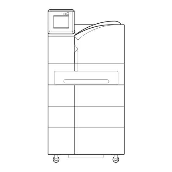
Ch.1 Pre-installation Information Part Names DRYPRO 793 Part names required for installation are detailed below. 1.4.1 Front, Top and Left Sides 1) Front Upper Cover 4) Exit Cover 2) Supply Tray 1 5) Left Cover 3) Front Lower Cover 1) Front Upper Cover 4) Exit Cover When a film jam occurs I the HPRO When a film jam occurs in the ejection... - Page 28 Ch.1 Pre-installation Information 1.4.2 Operation Panel 2) Operation Button 3) Operation Lamp 1) Operation Panel 4) Timer Lamp 1) Operation Panel Operates and performs various setting for DRYPRO 793. Also displays various messages. 2) Operation Button Starts up or shuts down DRYPRO 793. 3) Operation Lamp Operating : Constant blue...
- Page 29 Ch.1 Pre-installation Information 1.4.3 Rear and Right Sides 1) Film Exit Tray 7) Outlet 2) Front Upper Cover Release Lever 3) Right Cover 8) Inlet 9) Ethernet Port 4) Power Breaker 10) Serial Port 5) Power Cable Connector 6) Power Cable 1) Film Exit Tray 6) Power Cable Printed films are output to this tray.
- Page 30 Ch.1 Pre-installation Information LEDs at the Ethernet Port Two LEDs at the Ethernet port indicate the following. Lower right of the rear side Link / Activity LED Com. Speed LED - Link/Activity LED Com. Status Link Constant orange Activity Constant green - Com.
- Page 31 Ch.1 Pre-installation Information 1.4.4 Options 1. Supply Trays 2, 3 1) Supply Trays 2, 3 1) Supply Trays 2, 3 Holds film. 2. Lis-793 1) Lis-793 2) Sorter Cover 1) Lis-793 2) Sorter Cover Printed films are output to 5 bins in the When a film jam occurs in the sorter sorter and to to the film exit tray, transport unit, this cover may be opened...
- Page 32 Ch.1 Pre-installation Information 1.4.5 Interior 1) Lever-A 7) Deodorant Filter Case Housing (Yellow) 6) Deodorant Filter 2) Lever-B 4) Cover-B 5) Cover-C 3) Lever-C Be careful not to touch 1) Lever-A (Green) 5) Cover-C the deodorant filter Locks the deodorant filter case. When a film jam occurs between the housing (yellow) when justification unit and the elevator...
-
Page 33: Structure
Ch.1 Pre-installation Information Structure The internal structure of DRYPRO 793 is shown below. Film is transported in sequence from (1) through (7) during the printing process. 11) Lis-793 10) Operation Panel 8) Deodorant Filter 6) HPRO Unit 7) Cooling/Discharge Unit 1) Pickup Unit 5) Elevator Transport Unit... - Page 34 Ch.1 Pre-installation Information < 30 > DRYPRO Vstage MODEL 793 Installation Manual Ver.1.00 2004.11...
- Page 35 Chap. Unpacking and Installation This chapter details procedures for unpacking and installing DRYPRO 793. < 31 > DRYPRO Vstage MODEL 793 Installation Manual Ver.1.00 2004.11...
-
Page 36: Ch.2 Unpacking And Installation
Ch.2 Unpacking and Installation 2.1 Packing List This list shows all components included in the DRYPRO 793 packing. A check should be carried out to ensure that all components are present. If any components are missing, the package should be processed as an incomplete consignment. - Page 37 Ch.2 Unpacking and Installation 2.1.2 Supply Tray (Option) The components packed with supply tray are listed below. Component Name Quantity Remarks Tray Unit Includes accuride rails Pick up Unit Accuride Rails Cable (CH3 Signal Assy) Pickup Unit ~ Mech Cntl Board Cable (CH3 Power Assy) Pickup Unit ~ Power IF Board Pick-up Unit Securing Component...
- Page 38 Ch.2 Unpacking and Installation 2.1.4 1GB Print Memory (Option) This memory increases the DRYPRO 793 image processing speed. The 1GB print memory is essential for 25µm output using the Regius-PCM system. The components packed with the 1GB print memory are listed below. Component Name Quantity Remarks...
-
Page 39: Unpacking
Ch.2 Unpacking and Installation 2.2 Unpacking The procedure for unpacking DRYPRO 793 is detailed below. The weight of the main body of DRYPRO 793 is approximately 255Kg (without Disposal of the packing sorter)/285kg (with sorter). The weight of the unit with packing is approximately materials should be 313.5kg (without sorter). - Page 40 Ch.2 Unpacking and Installation Cut the bands securing the ramp (attached to the rear of the main body) and the accessories boxes (attached to all sides of the main body) and set the ramp in a place where it will not obstruct unloading work.
- Page 41 Ch.2 Unpacking and Installation Insert the removed lever plate frame from the rear between the main body and the palette as illustrated. Raise the main body by turning the lever plate screw using a socket wrench with ratchet and 3 ~ 5cm DRYPRO 793 remove the shock absorbers from the underside of the main body.
-
Page 42: Checking Accessories
Ch.2 Unpacking and Installation 2.3 Checking Accessories The accessories listed below are provided with DRYPRO 793. Check to ensure that all accessories are present. If any components are missing, the package should be processed as an incomplete consignment. Component Quantity Remarks Page Warranty... -
Page 43: Protection Hardware (Red) List
Ch.2 Unpacking and Installation 2.4 Removing Protection Hardware (Red) Parts and Installing Optional Units Protection hardware are set inside the device to prevent potential damage to internal components caused by exposure to shock or vibration during transport. Protection hardware must be removed in the sequence set out in this manual after transporting the device to the place of installation. -
Page 44: Removing Protection Hardware Securing Back Of Exposure Unit
Ch.2 Unpacking and Installation 2.4.2 Removing Protection Hardware Securing Back of Exposure Unit The procedure for removal of the components securing rear of exposure unit is described below. Use fingers to remove the cap located at the bottom of the right side of the main body. Disengage the lower front cover lock by inserting a driver with a shaft length of 90mm or more shown below into the hole revealed at the... -
Page 45: Removing Protection Hardware Securing Front Of Exposure Unit
Ch.2 Unpacking and Installation Remove the two screws (TP screws M4X8) at the outer edges of the protection hardware Be sure to keep the securing the rear of the exposure unit, leaving protection hardware the third securing screw in place, and securing the rear of the horizontally pull out the protection hardware. -
Page 46: Removing Protective Film From Exposure Unit Conveyor Rollers
Ch.2 Unpacking and Installation 2.4.4 Removing Protective Film from Exposure Unit Conveyor Rollers After removal of the protection hardware at the front of the exposure unit, 2 protective films should be removed from the exposure unit conveyor rollers. Open the left cover by pressing lever-B (green). Remove the tape securing the exposure unit conveyor roller protective film to the DRYPRO 793 main body. -
Page 47: Removing Protection Hardware Securing Pickup Unit (X 2 Trays)
Ch.2 Unpacking and Installation 2.4.5 Removing Protection Hardware Securing Pickup Unit (X 1 trays) After removal of the protective film from the exposure unit conveyor rollers, the protection hardware securing the supply tray 1 pick units should be removed. Disengage the upper front cover disengaging lever and open the upper front cover. - Page 48 Ch.2 Unpacking and Installation Loosen the 2 screws (TP screws M4X8) and remove the supply tray 1 cover. Tray Cover 正面のネジ2本(TPネジM4x8)を外し、両端のネ ジ各1本(TPネジM4x8)を緩めて, and remove the supply tray 1 front cover. Remove the screw (TP screw M4X8) securing the protection hardware securing the pick up unit and remove the component.
- Page 49 Ch.2 Unpacking and Installation 2.4.6 Installing Supply Tray (Option) After removal of the protection hardware securing the pickup unit, the optional supply tray 2&3 may be installed. Check to ensure that all supply tray (option) components are included in the consignment. Disengage the supply tray 1 lock by inserting a driver with a shaft length of 90mm or more shown below into the hole at the right side of the...
- Page 50 Ch.2 Unpacking and Installation 正面のネジ2本(TPネジM4x8)を外し、両端のネ ジ各1本(TPネジM4x8)を緩めて、 remove the Removed covers blindfold front cover from supply tray 2. should be kept for use - The blindfold front cover is no longer needed. in the event that unnecessary options are removed in the future.
- Page 51 Ch.2 Unpacking and Installation Secure the Accuride rail to the slide support at the right side of the main body. Accuride rail hooks should be inserted into the square holes in the slide supports (2 holes each at the front and back of the main body). Extend the Accuride rails until the screw holes are visible.
- Page 52 Ch.2 Unpacking and Installation Slide left and right Accuride rails into the main body. Sliding Accuride rails out to their fullest extent engages a lock rendering it impossible to slide the rails back into the unit. The lock may be disengaged using a finger (1) and then slid back into the unit (2).
- Page 53 Ch.2 Unpacking and Installation Holding the pickup unit by both sides, as illustrated in the photograph, set the unit on the two rails in the main body and set in place. Remove one screw (TP screw M4x8) from the position illustrates in the left. Align the embosses to the receptacle holes (one Screw hole for securing togeher...
- Page 54 Ch.2 Unpacking and Installation Remove the 5 screws (Truss screws M4X8) and remove the rear cover. From this point on, the procedure involves handling circuit boards: a wristband must be worn. Secure the pickup unit to the rear side of the main body using one screw (TP screw M4X8) at the location shown at left.
- Page 55 Ch.2 Unpacking and Installation Connect connector M15 of the accessory cable (CH Signal Assy) to MC15 on the mechanical MCN15 control board in the main body. CN15 CH3 Signal Assy Mech Ctl Board Secure the cable (CH Signal Assy) to the DRYPRO 793 main body at the location shown at left (yellow square) using a clamp.
- Page 56 Ch.2 Unpacking and Installation Secure the supply tray 2 front cover using 2 screws the front (TP screws M3X6) and one screw at each edge (TP screws M3X6). Secure the supply tray 3 cover into position using 2 screws (TP screws M4X8). Slide supply tray 3 into position into the main body.
-
Page 57: Replacing The Removed Covers (1)
Ch.2 Unpacking and Installation 2.4.7 Replacing the Removed covers This section describes procedures for replacing covers removed during work procedures. Disengage the upper front cover disengaging lever and open the upper front cover. Disengage the supply tray 1 lock by inserting a driver with a shaft length of 90mm or more into the hole at the right side of the main body and pressing down the latch. - Page 58 Ch.2 Unpacking and Installation Slide supply tray 1 into place. Disengage the supply tray 2 lock by inserting a driver with a shaft length of 90mm or more into the hole at the right side of the main body and pressing down the latch.
- Page 59 Ch.2 Unpacking and Installation Slide supply 2 into place. Close the right cover. Close the left cover. Secure the exposure unit cover into place using 5 screws (TP screws M4X8). Close the lower front cover. < 55 > DRYPRO Vstage MODEL 793 Installation Manual Ver.1.00 2004.11...
- Page 60 Ch.2 Unpacking and Installation Affix film size labels to the level positions on each of the supply trays. - Proceed to removal of protective sheets from the heat processing drum (2.4.8). Leave the front cover open for subsequent procedures. Example illustrating: Supply tray 1: 14X17.
- Page 61 Ch.2 Unpacking and Installation 2.4.8 Removing Protective Sheet from HPRO Unit The procedure for removal of the 14X14 film and the mylar mat used to protect the HPRO (Heat Processing Unit) drum from vibration or shock is detailed below. Loosen 1 screw (Sems 2M3X14) and remove the connector cover from the inside of the main body.
- Page 62 Ch.2 Unpacking and Installation Remove the 2 cables on the far side of the HPRO unit from their clamps. Loosen the 4 screws (Sems 2 M4X8) at the front and rear of the upper cover (HPRO unit). The screws securing the HPRO unit cover Upper Cover are designed so that...
- Page 63 Ch.2 Unpacking and Installation As shown at left, tilt the upper opposing rack 90˚ with its outer edge as fulcrum before removing. Tilt the upper opposing rack 90˚ with the fulcrum here. Check to ensure that bearings or springs are not damaged or loose.
- Page 64 Ch.2 Unpacking and Installation Set the heat-processing drum down on the upper opposing rack removed in step- Care must be taken not to touch or damage the surface of the heat-processing drum. Additionally, do not leave the drum unattended. Any damage to the drum will have adverse affects on output images.
- Page 65 Ch.2 Unpacking and Installation 2.4.9 Installing HPRO Unit After removing the heat-processing drum and checking for damage to any of the parts, the drum must be re-installed without delay. Holding the cable at the back of the heat- processing drum in the left hand, place the drum Be careful not to on the lower opposing rack.
- Page 66 Ch.2 Unpacking and Installation Set the upper opposing rack with the film inseted in the step-2 on the lever opposing rack, and tilt the upper opposing rack 90˚ with the fulcrum illustrated in the left. Tilt the upper opposing rack 90˚ with the fulcrum here.
- Page 67 Ch.2 Unpacking and Installation Tighten the 4 screws (Sems2 M4X8) at the front and back of the upper cover (heat- processing unit). Upper Cover Front Attach the cable at the far side of the heat- processing unit the 2 clamps. Holding the 3 heat-processing drum cables in the left hand, return the heat exposure unit slide plate into the main body.
- Page 68 Ch.2 Unpacking and Installation Reconnect the HPRO drum connectors at three locations (CN-A, CN-B, CN3). CN-B CN-A Tighten 1 screw (Sems 2 M3X14) to secure the connector cover. Ensure that the connector cover meshes with the lug at the back of the main body interior.
-
Page 69: Installing Deodorant Filter And Deodorant Filter Case
Ch.2 Unpacking and Installation 2.4.10 Installing Deodorant Filter and Deodorant Filter Case The procedure for installing the deodorant filter and case packed with DRYPRO 793 is described below. Remove the deodorant filter and case from the packing box. - The deodorant filter is packed in bubble packing and a vinyl bag. - Page 70 Ch.2 Unpacking and Installation Set the deodorant filer in the filter case. - As shown at left, the filter should be inserted with the handle at the front and the holes in the cardboard at the top. Close the deodorant filter case lid. Slide the deodorant filter case lid to the right (1).
-
Page 71: Installing Lis-793 (Option)
Ch.2 Unpacking and Installation 2.4.11 Installing Lis-793 (Option) The procedure for installation of Lis-793 is described below. Remove the 5 screws (Truss screws M4X8) and remove the rear cover. Remove the 2 screws (Truss screws M4X8) and remove the upper left cover. Removed covers - To remove the upper left cover, slide it toward the should be kept for use... - Page 72 Ch.2 Unpacking and Installation Remove the 4 screws (TP screws M3X6) and remove the heat-processing discharge unit Components no guide. needed should be kept - The removed heat-processing discharge unit cover for use in the event that is no longer needed. unnecessary options are removed in the future.
- Page 73 Ch.2 Unpacking and Installation Holding the points marked "OK" (blue) in the illustration at left, lift up the sorter main body. Be sure not to hold the unit at points marked "NG" (red). Set the sorter main body down on the separation unit.
- Page 74 Ch.2 Unpacking and Installation Connect the connector (UJJ8) on the unit drive board of the sorter main body and the accessory cable (Sorter Signal Assy) connector (UJP8). Unit Drive Board UJJ8 UJP8 Secure the cable (Sorter Signal Assy) to the Sorter Signal Assy DRYPRO 793 main body in the clamps at the locations shown at left (rectangles shown...
- Page 75 Ch.2 Unpacking and Installation Set the rear cover of the sorter down in the Sorter Rear Cover location shown at left. Tighten the operation unit screws loosened in step- - This will secure the sorter front cover to the main body.
- Page 76 Ch.2 Unpacking and Installation Fix the bins on the bottom level of the sorter in place. Ensure that the five bins are firmly connected to the sorter main body. Fix the bins on the 2nd through 5th levels in place in the same way. Install the hold-down bracket using the 2 screws (TP screws M4X6).
- Page 77 Ch.2 Unpacking and Installation Blindfold Install the blindfold using the 2 screws (TP screws M4X6). Top Cover Place the top cover removed in step- location shown at left. Install the left cover of the sorter using the 6 screws (Truss screws M4X8). - The left cover should cover the top cover.
- Page 78 Ch.2 Unpacking and Installation Open the sorter cover outward. Attach the wire to the near side of the sorter guide using one screw (Sems 2 M3x6). Attach the other end of wire to the sorter the cover using one screw (Sems 2 M3x6). Attach the wire to the sorter guide and sorter cover of the far side in the same number.
-
Page 79: Installing 1Gb Print Memory (Option)
Ch.2 Unpacking and Installation 2.4.12 Installing 1GB Print Memory (Option) In configurations including the 1GB print memory option, the memory should be installing the supply tray. Since the following procedure involves handling circuit boards, wristbands must be worn. Installation or removal of the memory should be carried out only after ensuring that the power cable is disconnected from the main body. - Page 80 Ch.2 Unpacking and Installation Open the lock levers at both edges of the DIMM Opening the lock levers socket on the print engine board to both sides too forcefully may result Print Engine Board and remove the 512MB memory module. in the memory module being dropped.
-
Page 81: Replacing The Removed Covers (2)
Ch.2 Unpacking and Installation Connect the connector at the right edge of the control box (SJP2). SJJ2 Fix the relay box in place using the 2 screws (TP screws M4X8). Relay Box Cover In cases where the 1GB print memory is installed, ensure that the print memory is p.102 SYSTEM properly recognized in the [SYSTEM SETUP] (SERVICE SETUP1) in the service SETUP... -
Page 82: Installing Accessories
Ch.2 Unpacking and Installation 2.5 Installing Accessories The procedure for installing accessories included in the DRYPRO 793 consignment is described below. 2.5.1 Installing Exhaust Duct The procedure for installation of the exhaust duct is described below. Installation of the exhaust duct produces a downward directed exhaust flow and also reduces fan- generated noise. -
Page 83: Changing Supply Tray Film Size Setting
Ch.2 Unpacking and Installation 2.5.3 Changing Supply Tray Film Size Setting (14 inch tray only) In facilities where 14X14" or 14X11" film is used, it is necessary to adjust the position of the size stopper in the supply tray. - The stopper position is set to 14X17" at the factory. Since supply trays for small sizes (10X12"... - Page 84 Ch.2 Unpacking and Installation Insert a driver with a shaft length of 90mm or more shown below into the hole on the right side of the main body press the supply tray latch. - This will disengage the supply tray lock. Remove the 2 screws (Sems 2 M4X15) from 14X11"...
-
Page 85: Installing Ups (Option)
Ch.2 Unpacking and Installation 2.5.4 Installing UPS (Option) The procedure for installing the UPS in DRYPRO 793 is described below. 1. Operation The operation of both recommended and non-recommended UPS is described below. When the recommended UPS is used: - Upon occurrence of a power outage, DRYPRO 793 will power down in the same way as when the power switch is pressed. - Page 86 Ch.2 Unpacking and Installation 4. Connection to DRYPRO 793 (Recommended Product) Back of DRYPRO 793 Switch off the DRYPRO 793 power supply. Connect the serial cable to the serial connector at the back of DRYPRO 793. Connect the other end of the serial cable Serial Cable connected in step- to the UPS.
-
Page 87: Starting Up
Ch.2 Unpacking and Installation 2.6 Starting Up The procedure for starting up DRYPRO 793 after completion of all installation and part removals is described below. 2.6.1 Switching On Power The procedure for switching on DRYPRO 793 power is described below. Check to ensure that the breaker at the bottom of the right cover of DRYPRO 793 is off. - Page 88 Ch.2 Unpacking and Installation < 84 > DRYPRO Vstage MODEL 793 Installation Manual Ver.1.00 2004.11...
- Page 89 Chap. Setup This chapter describes procedures for making DRYPRO 793 settings. < 85 > DRYPRO Vstage MODEL 793 Installation Manual Ver.1.00 2004.11...
-
Page 90: Ch.3 Setup
- TIME SET : Check and setting of the DRYPRO 793 internal clock and p.124 TIME SET setting of the time and date display format. - MAINTENANCE SCHEDULE : Initialization of the regular DRYPRO793 inspection p.128 MAINTENANCE schedule. SCHEDULE [OTHER SETUP]... - Page 91 Ch.3 Setup 3.1.2 Set Value Input Screen The procedure for manipulation of the set value input screen in the maintenance mode is described below. 1) Set Value Display Field 7) [0] ~ [9] Button Displays current set values and setting Used for input of numerical values from 0 ranges.
-
Page 92: Switching To The Service Maintenance Mode
Ch.3 Setup 3.2 Switching to the Service Maintenance Mode The procedure for switching to the service maintenance mode is described below. Touch the [MENU] button. - The menu mode screen will be displayed. Touch the [Maintenance] button. - Since the default log-in password setting is ON, the user selection screen is displayed. -
Page 93: Switching To The Normal Screen From The Service Maintenance Mode
Ch.3 Setup Input the service password (5678). - The input password will be displayed as a series of asterisks (*). Touch the [OK] button. - If the input password is correct, the user maintenance mode screen will be displayed. - If the input password in incorrect, a message indicating input of an incorrect password will be displayed. -
Page 94: Film Setup
Ch.3 Setup 3.4 Film Setup The procedure for making film size and type settings for film output by DRYPRO 793 is described below. Although the film sizes and types for DRYPRO722/751/752 are read automatically from the film package, these settings must each be input in the DRYPRO 793 maintenance mode. - Page 95 Ch.3 Setup The following conditions apply to setting changes. Film size, type, count and package count settings are not possible for trays whose [Tray Use] is set to [Not in Use]. Film size, type, count and package count settings are not possible. When the [Tray Use] is set to [Not in Use].
- Page 96 Ch.3 Setup p.86 Switching to Switch to the service maintenance mode. the Service Maintenance Mode Touch the [TRAY] button. - The film setup buttons will be displayed. Touch the [FILM SETUP] button. - The film setup screen (1/3) will be displayed. Set the film size, type and count for trays 1-3.
- Page 97 Ch.3 Setup Touch the [>] button at the bottom left of the screen once. - The film setup screen (3/3) will be displayed. Make tray series use, continuous film setup and mounted tray count settings. - Use the "ON" or "OFF" buttons to active or deactivate tray series use and continuous film setup.
- Page 98 Ch.3 Setup The message shown at the right will be displayed if settings are incorrect. "Data setting is incorrect." The type specified is inappropriate for the set film size. "Failed to store because the value was different from the machine setup. It will be returned to previous value."...
-
Page 99: Scp Setup
Ch.3 Setup 3.5 SCP Setup The procedure for making SCP settings (DICOM information for DRYPRO 793 itself) is described below. p.172 SCP Setup (Web Mainte. Mode) Item Default Descriptions IP ADDRESS 192.168.20.161 Sets the DRYPRO 793 IP address. SUBNET MASK 255.255.255.0 Sets the network sub-net mask. - Page 100 Ch.3 Setup p.86 Switching to Switch to the service maintenance mode. the Service Maintenance Mode Touch the [SERVICE 1] button. - The installation setup buttons will be displayed. Touch the [SCP SETUP] button. - The SCP setup screen (1/2) will be displayed. p.85 Set Value Set the IP address, subnet mask, gateway and Input Screen...
- Page 101 Ch.3 Setup Touch the [SAVE] button. - Settings will be saved and display returned to the service maintenance screen. Touching the [Return] button during the process of making setting changes will produce display of a message requesting confirmation of whether or not to save settings.
-
Page 102: Scu Setup
Ch.3 Setup 3.6 SCU Setup The procedure for making SCU settings (DICOM information for diagnostic devices connected to DRYPRO 793) is described below. p.173 SCU Setup The following SCU settings should be made. (Web Mainte. Mode) The default settings for each of the DICOM SCU items are based on connection of CS-1/CS-2 (CH1), Printlink2 (CH2) , CS-3(CH3)(one of each connected). - Page 103 Ch.3 Setup The relationship between communication between DRYPRO 793 and external devices according to DICOM error level settings is shown below. In warming up, ready to print and tray empty statuses (when the film empty notice is set to "OFF". Including the relation in film empty status.) DICOM Communication Print Job DRYPRO 793 Status Displayed...
- Page 104 Ch.3 Setup Item Default Descriptions SIZE TYPE CHECK CH01~16 : ON This setting determines whether or not film information (film size, type) sent by diagnostic devices is checked. "ON" : Information is checked. Error is returned to the diagnostic device if film size or type in incorrect.
- Page 105 Ch.3 Setup p.86 Switching to Switch to the service maintenance mode. the Service Maintenance Mode Touch the [SERVICE 1] button. - The installation setup buttons will be displayed. Touch the [SCU SETUP] button. - An input device selection screen will be displayed. - The following three input devices are set as default.
- Page 106 Ch.3 Setup Set the input device N-EVENT port number, AE title and DICOM error level. - Touching the input device N-EVENT port number, AE title buttons will produce display of a set value input screen. - Use the [<][>] buttons to switch between DICOM error level settings.
- Page 107 Ch.3 Setup Touching the [Return] button during the process of making setting changes will produce display of a message requesting confirmation of whether or not to save settings. [Yes] : Settings will be saved and display returned to the service maintenance screen.
-
Page 108: System Setup
Ch.3 Setup 3.7 System Setup The procedure for making DRYPRO 793 system operational settings is described below. The following system settings should be made. p.177 System Setup Changing and saving system settings will result in automatic re-initialization of (Web Mainte. Mode) DRYPRO 793. - Page 109 Ch.3 Setup p.86 Switching to Switch to the service maintenance mode. the Service Maintenance Mode Touch the [SERVICE 1] button. - The installation setup buttons will be displayed. Touch the [SYSTEM SETUP] button. - The system setup screen (1/2) will be displayed. Set the log-in password, language used and log acquisition mode.
- Page 110 Ch.3 Setup Touch the [SAVE] button. - Settings will be saved and the device automatically rebooted. - After rebooting, the normal screen will be displayed. Touching the [Return] button during the process of making setting changes will produce display of a message requesting confirmation of whether or not to save settings.
-
Page 111: User Registration
Ch.3 Setup 3.8 User Registration Procedures for registration/amendment/deletion of user information in DRYPRO 793 are described below. A total of 16 user data maybe registered. p.179 NEW USER The following user registration setting may be made. (Web Mainte. Mode) The settings detailed below are unnecessary if the log-in password has been set to "OFF."... - Page 112 Ch.3 Setup Display of User Selection Screen Before carrying out registration/amendment/deletion of user information, the user selection screen must first be displayed. The procedure for displaying the user selection screen is described below. p.86 Switching to Switch to the service maintenance mode. the Service Maintenance Mode...
- Page 113 Ch.3 Setup p.85 Set Value Set the user name, user privilege, password and Input Screen password confirmation. - Touching the user name or user privilege will produce display of a set value input screen. - Use the [<][>] buttons to switch between user privilege displays.
- Page 114 Ch.3 Setup Amending User Information The procedure for amending user information already registered is described below. Touch the button corresponding to the user name for which amendments are to be carried out. - The user registration screen will be displayed. p.85 Set Value Set the user privilege, password and password Input Screen...
- Page 115 Ch.3 Setup Touching the [Return] button during the process of making setting changes will produce display of a message requesting confirmation of whether or not to save settings. [Yes] : Settings will be saved and display returned to the service maintenance screen.
- Page 116 Ch.3 Setup 3.9 Print Condition Settings The procedure for setting print conditions for each diagnostic device connected is described below. The following print conditions may be set. p.181 PRINT CONDITION (Web Mainte. Mode) Item Default Descriptions LUT SELECT CH01~16 : 1 Sets the LUT number to be used.
- Page 117 Ch.3 Setup Item Default Descriptions BORDER CH01~16 : Black Sets the film background density. "Black" : Film is printed with black background density. "Clear" : Film is printed with clear background density. TRIM CH01 : OFF Sets trim to ON or OFF. CH02 : ON "ON"...
- Page 118 Ch.3 Setup Item Default Descriptions EDGE ENHANCEMENT CH1 : OFF This setting determines whether or not edge enhancement is carried out. CH2 : ON "ON" : Edge enhancement is carried out. CH03 : OFF "OFF" : Edge enhancement is not carried out. CH04~16 : ON BORDER SIZE CH1 : REGIUS...
- Page 119 Ch.3 Setup Item Default Descriptions INTEGRAL MULTIPLE CH01~16 : 1 Sets the enlargement ratio valid when smoothing is set "7." RATIO Used, for example, when the user wishes to specify print size, but the diagnostic device cannot send a specific size infomation of the requested image.
- Page 120 Ch.3 Setup Item Default Descriptions DEFAULT DMIN/DMAX CH01~16 : DICOM Sets acquisition target of maximum/minimum density values used only for image processing. "DICOM" : The value specified by the diagnostic device is used. "P-CON" : Maximum/minimum density data included in "LUT SETUP"...
- Page 121 Ch.3 Setup Make LUT selection, density (dark/light), contrast (strong/weak) and smoothing settings. - Use the [<][>] buttons to switch between the selection for LUT selection, density (dark/light), contrast (strong/weak) and smoothing settings. Touch the [>] button at the bottom left of the screen.
- Page 122 Ch.3 Setup Make stamp, stamp message and position settings. - Pushing the stamp setting button switches between ON and OFF. - Touching the stamp message display window produces display of a set value input screen. - Select the stamp position by touching either the "BOTTOM"...
- Page 123 Ch.3 Setup Touch the [>] button at the bottom left of the screen. - The print condition setting screen (7/7) will be displayed. Make default dmin/dmax and DICOM priority settings. - Use the [<][>] buttons to switch between default dmin/dmax settings. - Make the DICOM priority settings by touching either the "ON"...
-
Page 124: Lut Setup
Ch.3 Setup 3.10 LUT Settings An outline of DRYPRO 793 LUTs is presented below. A maximum of 7 LUT data may be registered in DRYPRO 793 for one diagnostic device. LUT data may be registered in one of the following three ways. (1) Registration of LUT data read from the DRYPRO 793 internal library. - Page 125 Ch.3 Setup Displaying the LUT Selection Screen Whichever method of LUT registration is used, the LUT selection screen must first be displayed. The procedure for displaying the LUT selection screen is described below. p.86 Switching to Switch to the service maintenance mode. the Service Maintenance Mode...
- Page 126 Ch.3 Setup Touch the [REFERENCE LIBRARY] button. - The LUT library screen will be displayed. Using the left/right scroll buttons, select the diagnostic device. - The LUT name corresponding to the selected device will be displayed. Touch the LUT name to be registered. Touch the [RETURN] button.
- Page 127 Ch.3 Setup Touching the [Return] button during the process of making setting changes will produce display of a message requesting confirmation of whether or not to save settings. [Yes] : Settings will be saved and display returned to the service maintenance screen.
- Page 128 Ch.3 Setup Touch the [RETURN] button. - The LUT setting screen will be displayed. Touch the [READ] button. - The reference library will be read and displayed at next to the edit LUT number. - The LUT value display will also be changed to the LUT value read.
- Page 129 Ch.3 Setup (3) Registration of newly created LUT data. The procedure for registration of newly created LUT data is described below. Select the LUT number to be registered by touching the scroll buttons at the left and right of the edit LUT number. To change the LUT value, touch the desired LUT value button (0 16).
-
Page 130: Time Set
Ch.3 Setup 3.11 Time Set The procedure for making changes to the DRYPRO 793 internal clock and for setting time.date display formats is described below. p.188 TIME SET To change the area code, first change the area code and proceed with time and (Web Mainte. - Page 131 Ch.3 Setup p.86 Switching to Switch to the service maintenance mode. the Service Maintenance Mode Touch the [TIMER] button. - The timer setup buttons will be displayed. Touch the [TIME SET] button. - The current time/date setup screen (1/2) will be displayed.
- Page 132 Ch.3 Setup Touch the [SAVE] button. - Settings will be saved and display returned to the service maintenance screen. Touching the [Return] button during the process of making setting changes will produce display of a message requesting confirmation of whether or not to save settings.
-
Page 133: List Of Time Zones
Ch.3 Setup List of Time Zones Time zones and codes are shown below. Summer Summer Time Code Time Zone Time Code Time Zone Time Time Afghanistan Standard Time Israel Standard Time Alaskan Standard Time Korea Standard Time Arab Standard Time Mexico Standard Time Arabian Standard Time Mid-Atlantic Standard Time... -
Page 134: Maintenance Schedule
Ch.3 Setup 3.12 Maintenance Schedule The procedure for initializing the DRYPRO 793 Maintenance schedule is described below. During installation, the time elapsed between shipment and installation must be reset. All the items shown below must be reset. Maintenance schedule items to be initialized are shown below. p.190 MAINTENANCE SCHEDULE SETUP... - Page 135 Ch.3 Setup p.86 Switching to Switch to the service maintenance mode. the Service Maintenance Mode Touch the [TIMER] button. - The timer setup buttons will be displayed. Touch the [MAINTENANCE SCHEDULE] button. - The maintenance schedule screen will be displayed. Touch the [MAINTENANCE A] button.
- Page 136 Ch.3 Setup Touch the [SAVE] button after resetting all schedules. - Settings will be saved and display returned to the service maintenance screen. Touching the [Return] button during the process of making setting changes will produce display of a message requesting confirmation of whether or not to save settings.
-
Page 137: Sorter Setup
Ch.3 Setup 3.13 Sorter Setup Sets the DRYPRO 793 sorter usage status. p.191 SORTER Settings are unnecessary in cases where the sorter is not used. SETUP The following sorter settings should be made. (Web Mainte. Mode) Item Default Descriptions SORTER USE Sets the sorter usage status. - Page 138 Ch.3 Setup p.86 Switching to Switch to the service maintenance mode. the Service Maintenance Mode Touch the [OTHER] button. - The other setup buttons will be displayed. Touch the [SORTER SETUP] button. - The sorter setup screen (1/2) will be displayed. Make sorter usage and first bin settings.
- Page 139 Ch.3 Setup Touch the [SAVE] button. - Settings will be saved and display returned to the service maintenance screen. Touching the [Return] button during the process of making setting changes will produce display of a message requesting confirmation of whether or not to save settings.
- Page 140 Ch.3 Setup < 136 > DRYPRO Vstage MODEL 793 Installation Manual Ver.1.00 2004.11...
- Page 141 Chap. This chapter details procedures for checking that images output from DRYPRO 793 comply with Checking Image standards. In cases where the image output does not comply Quality with standards, the service maintenance tool may be used to make image adjustments. <...
-
Page 142: Ch.4 Checking Image Quality
Ch.4 Checking Image Quality 4.1 Loading Film Film should be loaded after completion of DRYPRO 793 settings. Touch the [FILM SET] button. - A message indicating that the tray is being open is displayed. Animated display of - The supply tray will open a few centimeters and an animated display of the film loading procedure procedure for pulling (pulling out the tray, removal of protective... - Page 143 Ch.4 Checking Image Quality Touch the [NEXT] button on the operation panel. Animated display of film - An animated display of the of the procedure for setting. loading film (film setting) will be shown. Take out the new film package from its box and load it into the supply tray with the bar code at the front left.
- Page 144 Ch.4 Checking Image Quality Insert the rear (far) edge of the package firmly between the hold down plate and the winding Animated display shaft spindle. showing closing of the shutter - removal of Ensure the front (near) edge protrudes from the light proof bag.
- Page 145 Ch.4 Checking Image Quality Return the cutter to the cutter pocket (location 3 at left). Push the supply tray back into the main body until it locks in position. Upon completion of film loading, the film count - Pushing the tray back into its original position will produce display of the message "The tray is value displayed in the getting ready.
-
Page 146: Calibrating Internal Densitometer
Ch.4 Checking Image Quality 4.2 Calibrating Internal Densitometer After completion of DRYPRO 793 installation and settings, the print image density must be calibrated. Firstly, the internal densitometer should, if necessary, be calibrated. 4.2.1 Conditions required for Calibration The internal densitometer should be calibrated if either of the following conditions exists at the facility where DRYPRO 793 is installed. - Page 147 Ch.4 Checking Image Quality 4.2.3 Conditions for Implementation The film types for which internal densitometer calibration is carried out are described blow. The following information should be used as reference only in cases where the internal densitometer is calibrated at the facility where DRYPRO 793 is installed. In facilities where multiple film types are used, one internal densitometer calibration for one specific film type will be valid for all film types.
- Page 148 Ch.4 Checking Image Quality 4.2.4 Procedure for Calibration of Internal Densitometer The procedure for calibration of the internal densitometer is described below. Print out one calibration sheet. 1)Invoke the menu mode by touching the menu key. 2)Touch the [CALIBRATION] button on the print setting menu screen.
- Page 149 Ch.4 Checking Image Quality Print out one internal densitometer calibration sheet. 1)Invoke the menu mode by touching the menu key. 2)log-in to the service maintenance mode using service privilege. 3)Touch the [CORRECTION] button under the [SERVICE 2] item. - The densitometer calibration/previous density value selection screen will be displayed.
- Page 150 Ch.4 Checking Image Quality Input the measured density values. 1)Touch the [NEXT] button on the tray selection/print screen. - The density value input screen will be displayed. 2)Input the density values measured in step-3. 3)Touch the [SAVE] button after completion of input. Be sure to touch the [Save] button after inputting values.
- Page 151 Ch.4 Checking Image Quality Check the results of calibration. 1)Touch the [RETURN] button after printing the calibration sheet. - Display will return to the service maintenance mode screen. 2)Touch the [CORRECTION] button under the [SERVICE 2] item again. - The densitometer calibration/previous density value selection screen will be displayed.
-
Page 152: Test Printing
Ch.4 Checking Image Quality 4.3 Test Printing After completion of calibration of the DRYPRO 793 internal densitometer, a test printing should be carried out to check image quality. For installation purposes, two flat patterns and one SMPTE pattern should be printed out to check image quality. - Page 153 Ch.4 Checking Image Quality 5)Select supply tray 1, a copy count of 1 and a density of 1.00 and touch the [Print] button. - The flat pattern will be registered in the queue. - The display will return to the service maintenance mode screen.
-
Page 154: Printing Smpte Pattern
Ch.4 Checking Image Quality 4.3.2 Printing SMPTE Pattern To check printed film density, one SMPTE pattern should be printed out from each tray. Print out one SMPTE pattern from supply tray 1. 1)Touch the menu to invoke the menu mode. 2)log-into the service maintenance mode using service privilege. - Page 155 Ch.4 Checking Image Quality 7)Touch the [RETURN] button. - Display will return to the normal screen. - The SMPTE pattern film will be printed. In the same way print one SMPTE pattern from supply tray 2. Likewise, print out one SMPTE pattern from supply tray 3, if installed.
-
Page 156: Flat Pattern Justification
Ch.4 Checking Image Quality 4.3.3 Flat Pattern Justification Check film for scratches, line or density inconsistencies using a light table. In cases where printed flat patterns show abnormalities, appropriate measures should be taken as detailed in the chapter dealing with resolving problems in the service manual. - Page 157 Ch.4 Checking Image Quality (2) For Film Sizes 10X12, 8X10 SMPTE patterns Check to ensure that the densitometer to be printed on 10X12, and used is adjusted to zero. 8X10 sizes contain two patterns on one sheet. Out of the 11 gray scale levels (12 points)on the SMPTE pattern, use the densitometer to measure the density value at one location at the top of the film (where there are density patches...
- Page 158 Ch.4 Checking Image Quality List of Standard Density Values in the SMPTE Pattern (Shows correspondence between maximum and minimum density settings) Chart-A (16 step gray scale) Film Setting Max. Density Min. Density Film Setting Max. Density Min. Density Clear Blue Point Min.
- Page 159 Ch.4 Checking Image Quality Chart-B (11 step gray scale) Film Setting Max. Density Min. Density Film Setting Max. Density Min. Density Clear Blue Point Min. Value Standard Value Max. Value Point Min. Value Standard Value Max. Value (*)100% none 100% Film Setting Max.
-
Page 160: Adjusting Image Data Write Start Position
Ch.4 Checking Image Quality 4.4 Adjusting Image Data Write Start Position After completion of test printing, the image data write start position should be checked and adjusted. The image data write start position can be checked by printing a frame pattern and measuring the difference between the unexposed margins at both edges of the film. - Page 161 Ch.4 Checking Image Quality 4.4.2 Making Adjustments of Write Start Position in the Main Scan Direction (Horizontal) The procedure for making adjustments in the main scan direction is described below. Turn the pattern so that the word "FRAME" can be correctly seen and use a ruler to measure the length of the unexposed margins at the left and right edges of the frame pattern.
- Page 162 Ch.4 Checking Image Quality If the unexposed left margin measured in step-1 is longer than the right, decrease the value shown on the [HD Offset] button for the corresponding film size by the difference. If the unexposed left margin measured in step-1 is shorter than the right, increase the value shown on the [HD Offset] button for the corresponding film size by the difference.
- Page 163 Ch.4 Checking Image Quality 4.4.3 Making Adjustments of Write Start Position in the Sub- Scan Direction (Vertical) The procedure for making adjustments in the sub-scan direction is described below. Turn the pattern so that the word "FRAME" can 2mm or less be correctly seen and use a ruler to measure the length of the unexposed margin at the top edge of the frame pattern.
- Page 164 Ch.4 Checking Image Quality Reduce the value shown on the [VD OFFSET] button by the length measured in step-1 minus 2mm. - The write start position will be adjusted accordingly. Touch the [SAVE] button. - Display will return to the service maintenance mode menu screen.
- Page 165 Chap. Finally, a print job should b sent from an external device to DRYPRO 793 and a check carried out to Printing from and ensure that printing is successfully executed. Backup of Setup Data After carrying out the above check, the DRYPRO 793 program/setting files should be backed up.
-
Page 166: Ch.5 Printing From And Backup Of External Devices
Ch.5 Printing from and Backup of External Devices 5.1 Printing from External Devices The procedure for carrying out a check to ensure that print jobs sent from external devices can be successfully printed is described below. Connect one end of the Ethernet cable to the Ethernet port (RJ45) at the back of DRYPRO 793. -
Page 167: Backup
Ch.5 Printing from and Backup of External Devices 5.2 Backup The procedure for backing up DRYPRO 793 program/setting files is described below. The following two types of backup should be carried out during installation. - Backup of DRYPRO 793 CF memory information on the hard disk. - Backup of DRYPRO 793 installation settings on the maintenance PC using the Web maintenance tool. - Page 168 Ch.5 Printing from and Backup of External Devices 5.2.2 Installation Information Backup (DRYPRO 793 -> Maintenance PC) The procedure for backing up settings for each device using the Web maintenance tool is described below. System Requirements In order to use the Web maintenance tool, the PC used must meet the following requirements.
- Page 169 Ch.5 Printing from and Backup of External Devices Click [LOGIN] at the top left of the screen. - The log-in screen will be displayed. Click [SERVICE] in the "User ID" box and input the service privilege password in the "Password" box.
- Page 170 Ch.5 Printing from and Backup of External Devices Click the [Save] button. - Backup will commence and progress indicated by display of messages. - To return to the top page without carrying out backup, click the [Cancel] button. - A file save dialogue will be displayed upon completion of backup.
- Page 171 Chap. While procedures for making settings using DRYPRO Web Maintenance 793 were described in "Chapter 3 Setup", settings may also be made from the maintenance PC. This Mode chapter deals with procedures for making settings from the Web maintenance mode. <...
-
Page 172: Ch.6 Web Maintenance Mode
Ch.6 Web Maintenance Mode 6.1 Outline of Web Maintenance Mode DRYPRO 793 is furnished with a Web maintenance mode, which allows maintenance on the device to be carried out externally by connection to the Internet. Using the Web maintenance mode allows the user to reference and make changes to settings from remote locations. The Web maintenance mode may be operated from the Internet Explorer using PC that meets the requirements listed below. -
Page 173: Starting Up And Terminating Web Maintenance Mode
Ch.6 Web Maintenance Mode 6.2 Starting Up and Terminating Web Maintenance Mode The procedure for starting up and closing menu and maintenance modes in the Web maintenance mode is described below. 6.2.1 Starting up the Web Maintenance Mode (Service Maintenance Mode) The procedure for starting up the Web Maintenance Mode (Service Maintenance Mode) is described below. - Page 174 Ch.6 Web Maintenance Mode Click the [log-in] button at the top right of the screen. - The log-in screen will be displayed. Click the user ID pull-down menu. -A list of user IDs will be displayed. Click "SERVICE." - The pull-down menu will be closed and "SERVICE" displayed in the user ID window.
- Page 175 Ch.6 Web Maintenance Mode 6.2.2 Terminating the Web Maintenance Mode The procedure for terminating the Web maintenance mode (maintenance mode) is described below. Click the [Log out] button at the top left of the screen. - aconfirmation screen will be displayed. Click the [OK] button.
-
Page 176: Web Maintenance Mode Menus
Ch.6 Web Maintenance Mode 6.3 Web Maintenance Mode Menus Web maintenance mode menus are described below. 6.3.1 Film Setup <Film Setting> p.170 FILM SETUP The procedure for making film size and type settings for film output by DRYPRO 793 is described below. - Page 177 Ch.6 Web Maintenance Mode Item Default Descriptions TRAY SERIES USE Sets operation for use of the same film size/type in multiple trays. "ON" : Multiple trays operate as one tray. 1つのトレイのフィルムが無くなっても、別のトレ イに同一フィルムサイズ/タイプのフィルムが残存 している場合、EMPTY状態にはなりません。 "OFF" : Multiple trays operate independently. 別トレイに同一フィルムサイズ/タイプのフィルム が残存していても、EMPTY状態になります。...
-
Page 178: Scp Setup
Ch.6 Web Maintenance Mode 6.3.2 SCP Setup <Service1> p.172 SCP Setup The procedure for making SCP settings (DICOM information of DRYPRO 793 itself) is described below. Item Default Descriptions IP ADDRESS 192.168.20.160 Sets the DRYPRO 793 IP address. SUBNET MASK 255.255.255.0 Sets the network sub-net mask. -
Page 179: Scu Setup
Ch.6 Web Maintenance Mode 6.3.3 SCU Setup <Service1> p.173 SCU Setup The procedure for making SCU settings (DICOM information of diagnostic devices connected to DRYPRO 793) is described below. The following SCU settings should be made. The default settings for each of the DICOM SCU items are based on connection of CS-1/CS-2 (CH1), Printlink2 (CH2), CS-3 (CH3) (one of each connected). - Page 180 Ch.6 Web Maintenance Mode Item Default Descriptions ERROR LEVEL CH1~16 : STANDARD Sets the method of returning DICOM errors to diagnostic devices. Do not make changes to this setting unless instructed to do so. <STANDARD> : DICOM N-GET responses: → WARNING Tray empty →...
- Page 181 Ch.6 Web Maintenance Mode Item Default Descriptions SIZE TYPE CHECK CH01~16 : ON This setting determines whether or not film information (film size, type) sent by diagnostic devices is checked. "ON" : Information is checked. Error is returned to the diagnostic device if film size or type in incorrect.
- Page 182 Ch.6 Web Maintenance Mode 6.3.4 Custom Border Setup p.110 PRINT <Service1> CONDITION The procedure for specifying the border size when "CUSTOM" has been selected under [BORDER SIZE] in the print condition setup is described below. The setting is valid only when "CUSTOM" has been selected under [BORDER SIZE] in the print condition setup Item Default...
-
Page 183: System Setup
Ch.6 Web Maintenance Mode 6.3.5 System Setup <Service1> p.102 System Setup The procedure for making DRYPRO 793 system operational settings is described below. The following system settings should be made. Changing and saving system settings will result in automatic re- initialization of DRYPRO 793. - Page 184 Ch.6 Web Maintenance Mode In cases where the optional memory expansion is installed, check that "1024" is shown in the display. (No setting changes are necessary.) < 180 > DRYPRO Vstage MODEL 793 Installation Manual Ver.1.00 2004.11...
-
Page 185: User Registration
Ch.6 Web Maintenance Mode 6.3.6 User Registration <Service1> p.105 NEW USER Procedures for registration/amendment/deletion of user information in DRYPRO 793 are described below. The settings detailed below are unnecessary if the log-in password has been set to "OFF." The user name cannot be changed when making amendments to user information. - Page 186 Ch.6 Web Maintenance Mode Item Default Descriptions [DELETE] Button — Allows deletion of registered user information. The screen below is displayed for the user name shown in the line indicated by the yellow arrow (>) below the menu display field. To proceed with deletion, click the [Delete] button.
- Page 187 Ch.6 Web Maintenance Mode 6.3.7 Print Condition Setting p.110 Print Condition <Print Setting> Setting The procedure for setting print conditions for each diagnostic device connected is described below. The following print conditions may be set. Item Default Descriptions LUT SELECT CH01~16 : 1 Sets the LUT number to be used.
- Page 188 Ch.6 Web Maintenance Mode Item Default Descriptions CONTRAST CH01~16 : 0 Sets the image contrast. Lower settings (-) produce lower contrast, higher settings (+) higher contrast. Settings may be made within a range of "-7" ~ "+7." SMOOTHING CH01~16 : 2 Sets the image smoothing type.
- Page 189 Ch.6 Web Maintenance Mode Item Default Descriptions BORDER SIDE CH1 : REGIUS This setting determines the border size. CH2 : CT_MRI "REGIUS" : Regius border size. CH03 : REGIUS "CT_MRI" : CT, MRI border size. CH04~16 : CT_MRI "CUSTOM" : Custom border size (Details may only be set in from the Web maintenance mode.) REQUESTED IMAGE SIZE CH01~16 : EFFECTIVE...
- Page 190 Ch.6 Web Maintenance Mode Item Default Descriptions FORMAT CH01 : CENTER This setting determines space allocation between frames in multi- CH02 : EVEN format printing. CH03 : CENTER "CENTER" : Central allocation. CH04~16 : EVEN "EVEN" : Even allocation. "H CENTER" : Central allocation (When diagnostic device is of Hitachi manufacture) "H EVEN"...
- Page 191 Ch.6 Web Maintenance Mode Item Default Descriptions STAMP SETUP CH01 : OFF This setting determines whether or not film is printed with a date < TIME/DATE > CH02 : ON stamp. CH03 : OFF "ON" : Date is printed. CH04~16 : ON "OFF"...
-
Page 192: Lut Setup
Ch.6 Web Maintenance Mode 6.3.8 LUT Setting <Print Setting> p.118 LUT SETUP The procedure for setting print conditions for each connected diagnostic device is described below. Item Descriptions LUT NO. Selects the LUT for which print conditions are to be set. Settings may be made within a range of "1"... - Page 193 Ch.6 Web Maintenance Mode Item Descriptions [COPY] Button Displays the LUT copy screen. Allows copying of LUTs. Select the LUT to be copied in the "Copy from" window and the LUT to which copy is to be sent in the "Copy to" window. After selecting the LUT in "Copy From"...
- Page 194 Ch.6 Web Maintenance Mode 6.3.9 Time Set <Timer Setting> p.124 TIME SET The procedure for making changes to the DRYPRO 793 internal clock and for setting time/date display formats is described below. To change the area code, first change the area code and proceed with time and date settings after the device...
- Page 195 Ch.6 Web Maintenance Mode Month formats are as follows: January February March April June Numerical Format(MM) Alphabetical Format(MMM) July August September October November December Numerical Format(MM) Alphabetical Format(MMM) List of Time Zones Time zones and codes are shown below. Summer Summer Time Code Time Zone...
-
Page 196: Maintenance Schedule Setup
Ch.6 Web Maintenance Mode 6.3.10 Maintenance Schedule <Timer Setting> p.128 Maintenance Schedule The procedure for initializing the DRYPRO 793 Maintenance schedule is described below. Setup During installation, the time elapsed between shipment and installation must be reset. All the items shown below must be reset. Maintenance schedule items to be initialized are shown below. -
Page 197: Sorter Setup
Ch.6 Web Maintenance Mode 6.3.11 Sorter Setup <Timer Setting> p.131 Sorter Setup Sets the DRYPRO 793 sorter usage status. Settings are unnecessary in cases where the sorter is not used. The following sorter settings should be made. Item Default Descriptions SORTER USE Sets the sorter usage status. - Page 198 Ch.6 Web Maintenance Mode < 194 > DRYPRO Vstage MODEL 793 Installation Manual Ver.1.00 2004.11...
-
Page 199: Specifications
Specifications Specifications of the DRYPRO 793 is detailed in the following pages. < 195 > DRYPRO Vstage MODEL 793 Installation Manual Ver.1.00 2004.11... - Page 200 Specifications Product Name Laser Imager DRYPRO Vstage MODEL 793 CODE No. CE : 0791 UL : 0792 Model DRYPRO Vstage MODEL 793 Laser Source Semiconductor Laser Film Type Medical Imaging Film SD-P, SD-PC, SD-PM Film Size 14 x 17 inch 14 x 14 inch 11 x 14 inch 10 x 12 inch...
- Page 201 Refer to the following URL for the full text of GNU General Public License (GPL). http://www.fsf.org/license/gpl.html Source code of the program used on the DRYPRO 793 can be downloaded from the following URL. http://www.konica minolta.jp/mi < 197 > DRYPRO Vstage MODEL 793 Installation Manual Ver.1.00 2004.11...
- Page 202 D-85662 Hohenbrunn, GERMANY TEL.973-633-1500 TEL.905-670-7722 TEL.8102-8040 KONICA FRANCE S.A. Konica Minolta Photo Imaging UK Ltd. Paris Nord II, 305 rue de la Belle Etoile, B.P. 50077, 95948 Plane Tree Crescent, Feltham, Middlesex ROISSY C.D.G. CEDEX, FRANCE TW13 7HD, U.K. TEL.1-4938-6550 TEL.20-8751-6121...
Need help?
Do you have a question about the DRYPRO793 and is the answer not in the manual?
Questions and answers